.JPG)
"Your source for standard gauge modeling in 1:20.3"
|
|
|
"Your source for standard gauge modeling in 1:20.3" |
|
|
The Freight Cars That Dave Built
(or is building)
|
|
The models below represent my work from about 2001 when I began my transition from Gauge 3, 1:22.5 scale to F gauge, 1:20.3 scale. So far I have built about four standard gauge cars in 1:20.3 (as of 10-1-09), but several others are in the planning or construction phase. For several years during this period (2003-2005), I did not have a viable workshop, so what hobby time I did have was spent on setting up my 23' x 25' shop. And each new little person (we are working up to #4 due in March of 2010) takes plenty of time, but my girls love trains--just like Dad--and help when they can. As of late, my hobby time has mainly been going into R&D with respect to freight car trucks and what I hope will eventually become a couple of kit cars (see below).
Want to build a freight car with me? I oftentimes have
some spare parts and welcome corroboration. Let's do it together! Half
the time--twice the fun! |
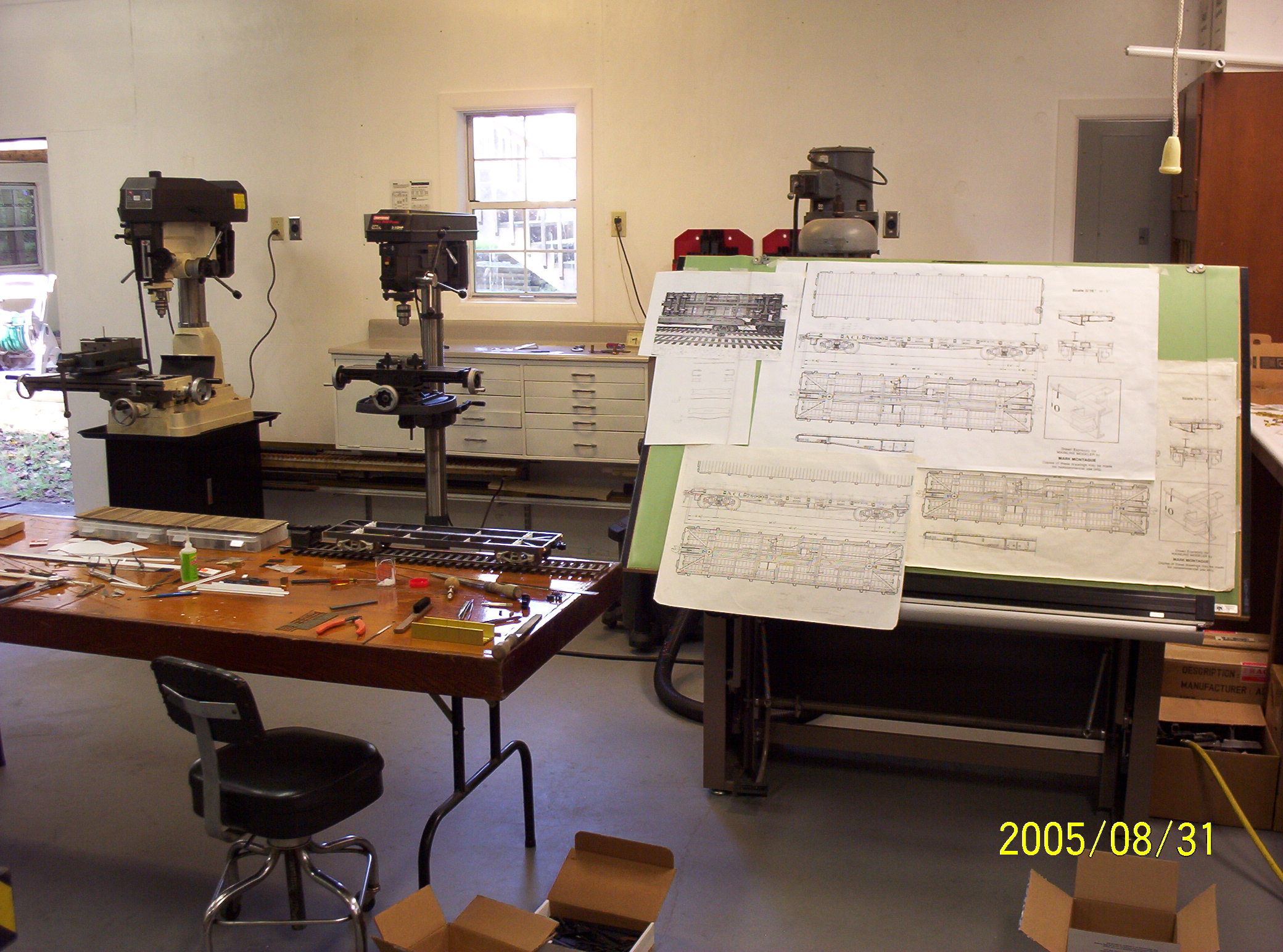
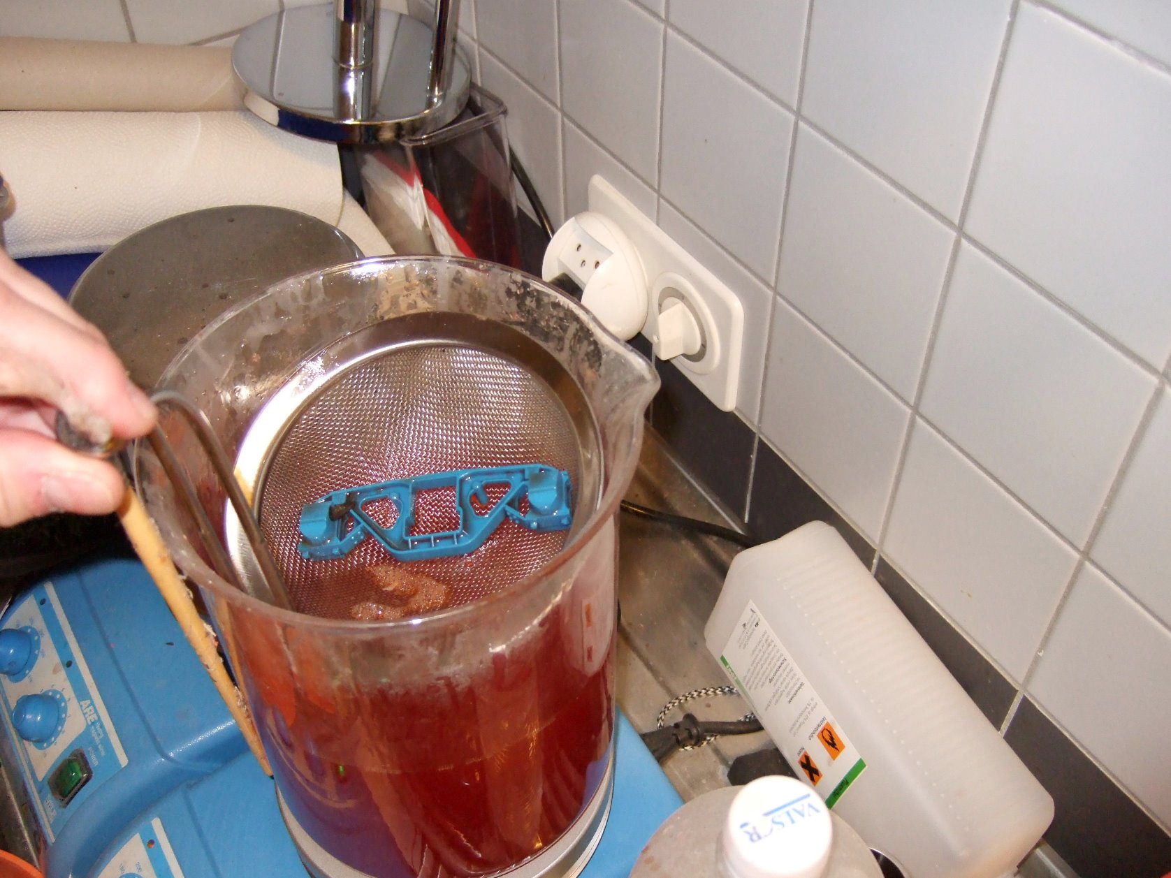
.JPG) Tools & Techniques Tools & TechniquesSince beginning to develop standard gauge modeling in F scale around 2001, the construction techniques that I have used in building freight cars has correspondingly evolved with the level of sophistication of the tools in my shop as well as the development of my own modeling skills. My earliest F scale cars were styrene & ABS one-off models, built in much the same way as my Gauge 3 rolling stock. Since then, however, I have progressed from hand-cut, hand-filed, and manually milled components to CAD drawn, laser cut & CNC machined ones. The reason is fairly simple: My long term goal is to build either fleets of freight cars for my own use and/or to move into short-run kit production (even now I can envision 100 car coal drags on a 1/20th scale Norfolk & Western outdoor railroad with As, Js, Mollies and all the rest--but I digress!). The three 40' American Car & Foundry flats at right are examples of my older one-off modeling techniques and are typical of what one man with a modest collection of hand tools can accomplish in styrene. By way of contrast, the Cass Scenic Railroad / Mower Lumber Co. logging flats below are illustrative of applying CAD/CAM technology to model-making and show how one man with the right software, access to a laser cutter, and a miniature table saw can get into building fleets of wooden rolling stock. Future additions to this page will include discussions of reproducing steel car prototypes through the application of rapid prototyping (RP) technology as well as making large, carbody sized urethane castings. For a foretaste of the latter, check out both Bob Uniack's gallery, as well as Barry Bog's Freight Cars, located elsewhere on this site. The One-Off Models
Speaking of fit, I've tried to keep components accurate not only by measuring twice with a scale rule and then carefully scribing lines using a machinist's square; but with structural shapes, before making any cuts with a razor saw, I allow an extra bit of material, cut, and then sand down to spec using a Micro-Mark rotary disc sander, checking as I go with either a 6" or 12" dial caliper. For really long lengths of plastic (12" and more), vernier calipers are available--and for those with the bucks, even larger sets of dial calipers. CA ("super-glue") usually holds the whole thing together, though I have also used Plastruct's Plastic Weld--basically just methyl ethyl ketone (MEK)--which is fine for joining large flat surfaces, but poor for butt joints or wherever minor irregularities between components result in gaps. In that case a gap-filling CA is far superior.
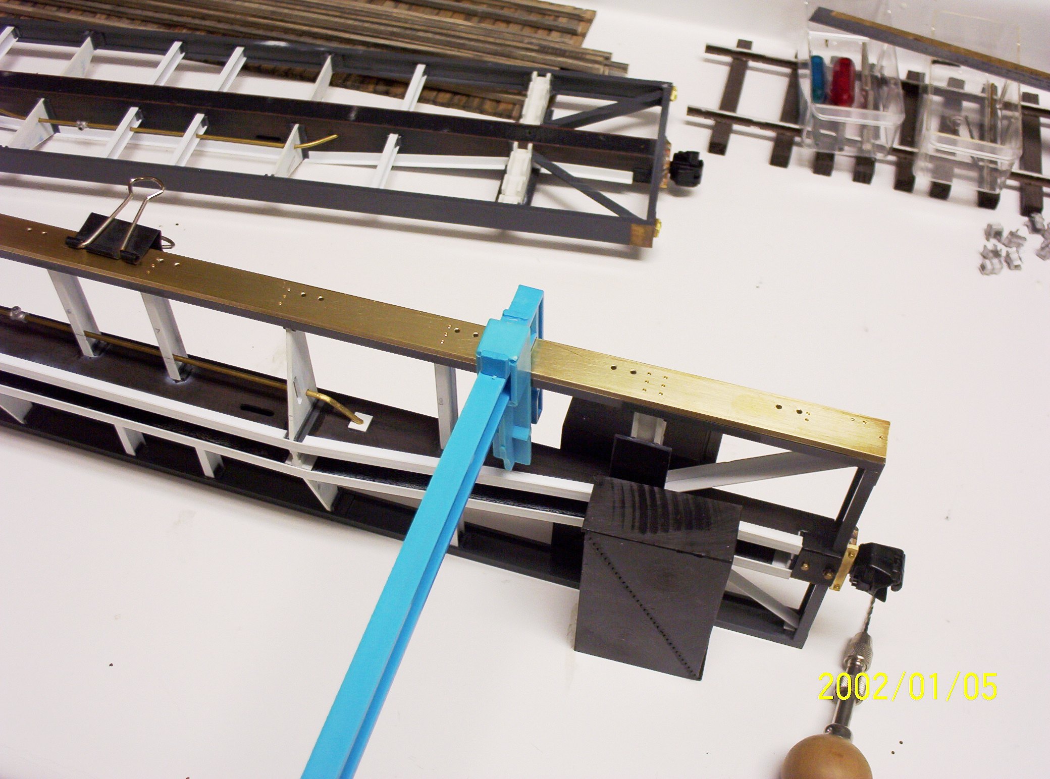
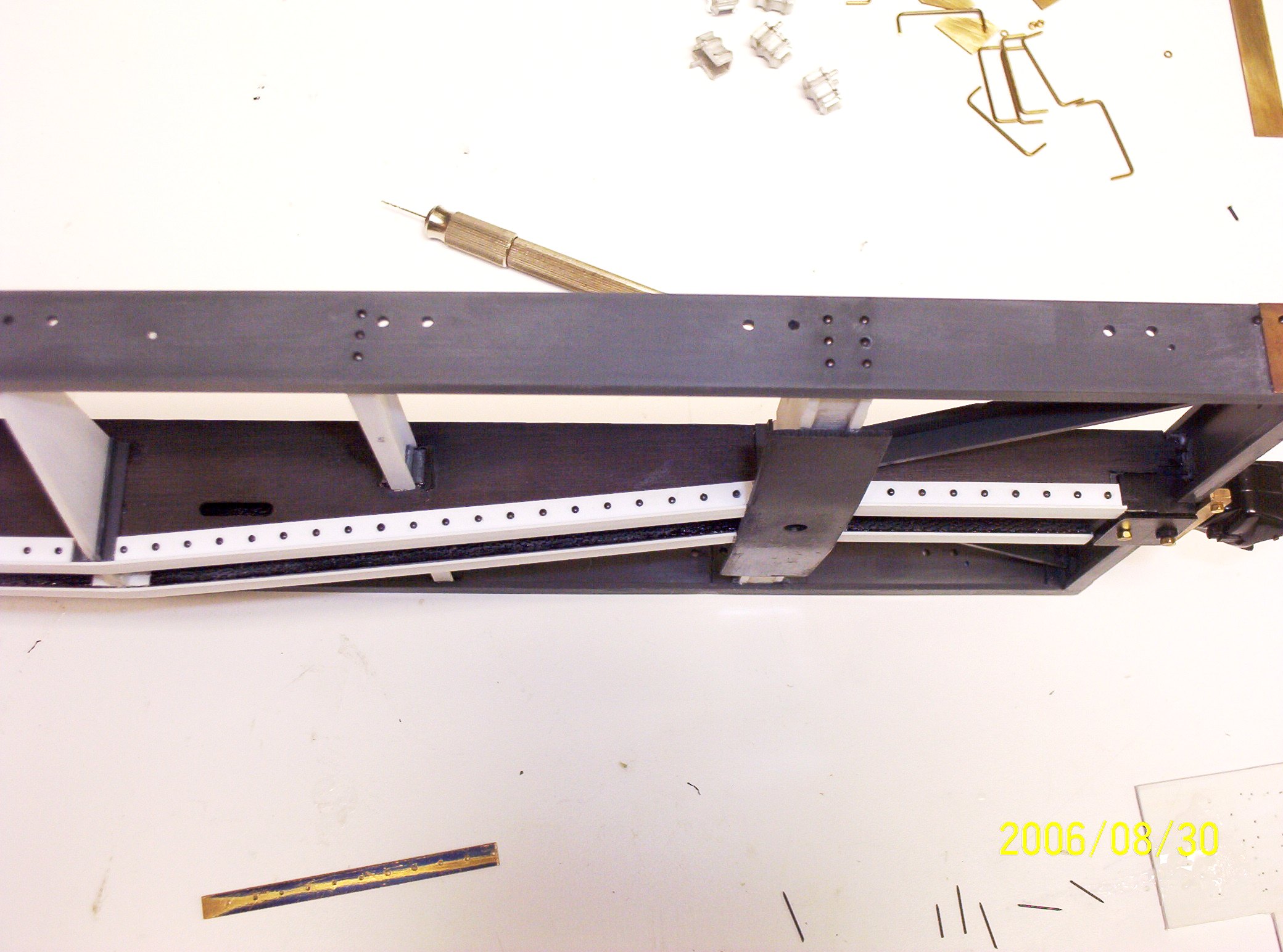
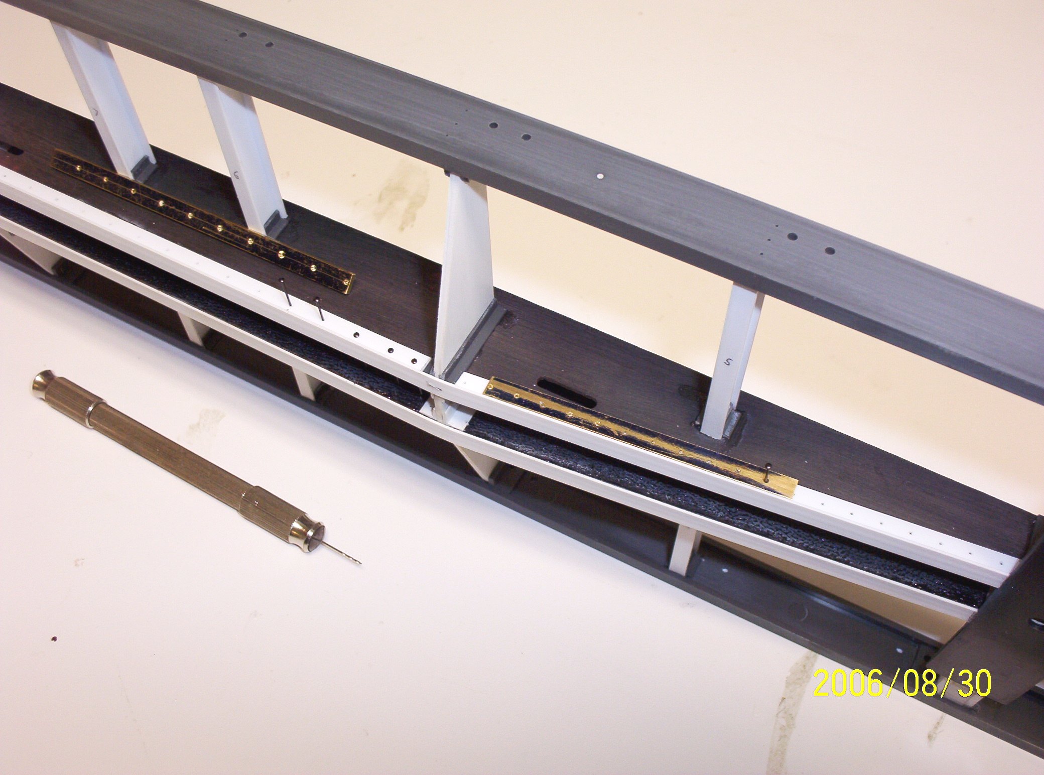
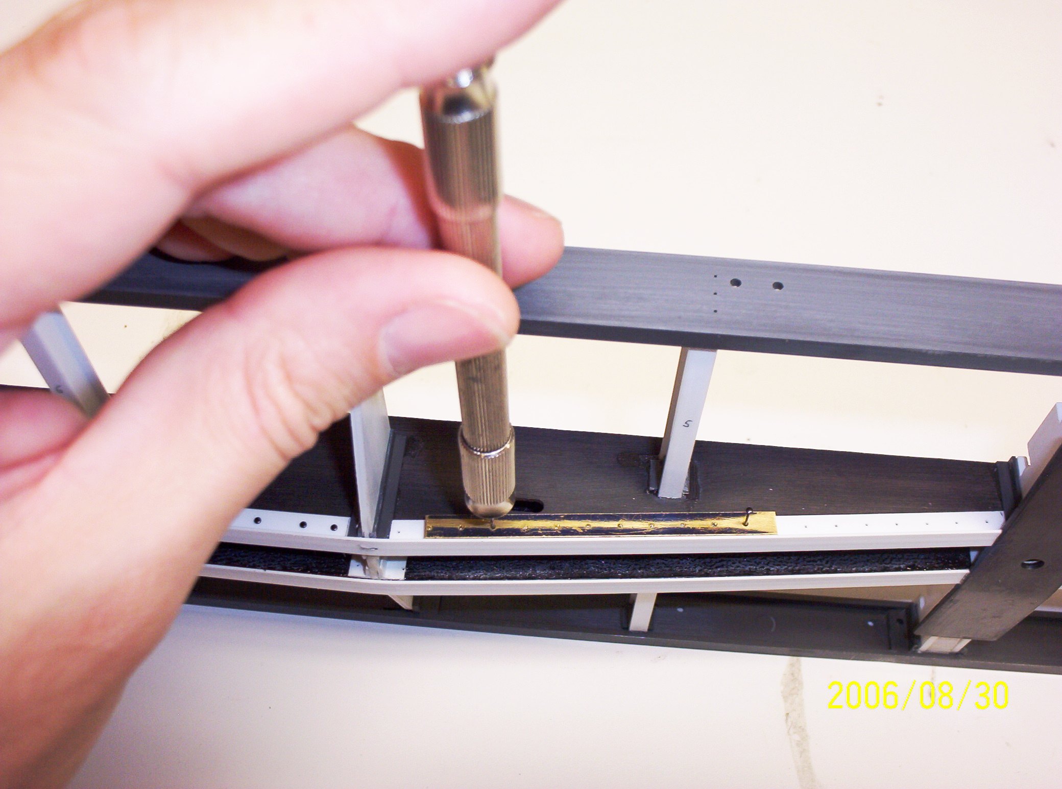
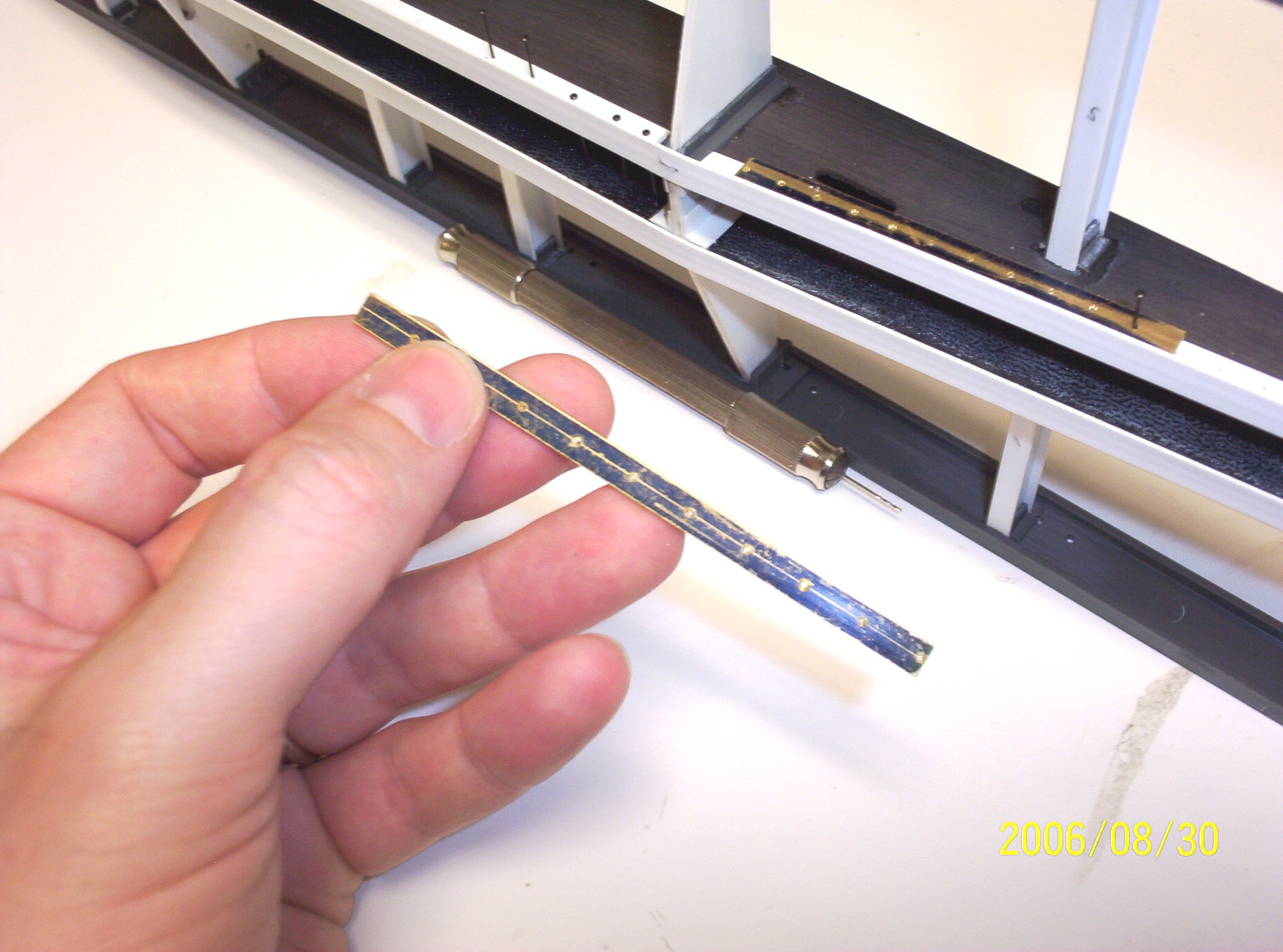
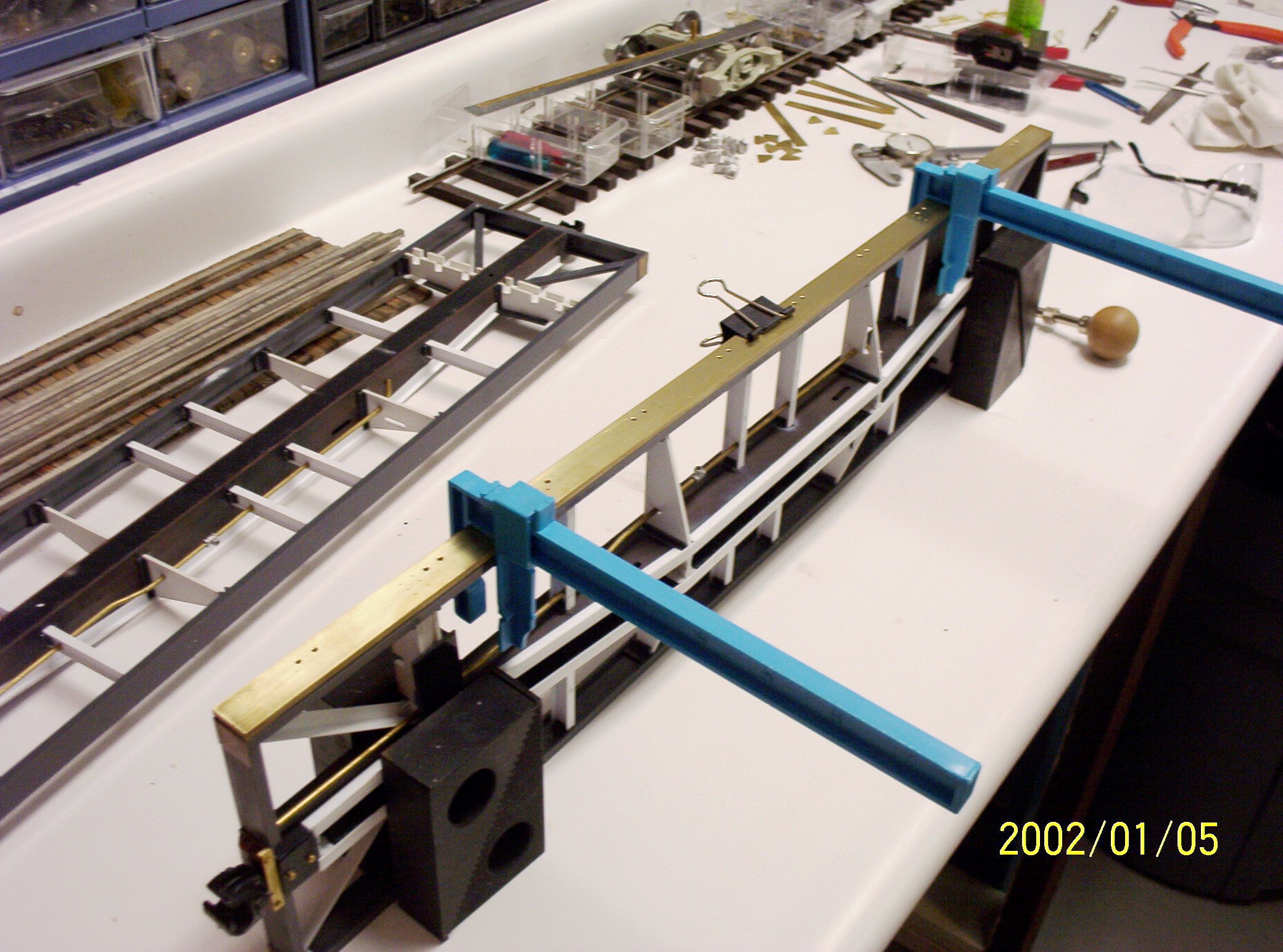
From the earliest days of the steel car era until the late 40s and early 1950s, rivets were the preferred method of holding steel plates together, in preference to bolts, both of which have been largely superseded by welding. So how does one duplicate all those hundreds of rivet heads found on a typical steam era freight car? There are several methods one might use: Thin plastic or brass is readily embossed with the right tools, imported brass models and many British freight car kits typically use photographically etched brass, actual miniature rivets are even available. But the method I settled on has been jig drilling properly spaced holes for small Peco brand track nails or sequin dress pins, and then with a dab of CA, pushing them home. Where larger rivet heads are needed, I have used both Atlas brand track nails as well as brass escutcheon pins. My drill guides are just strips of brass stock (K&S or Special Shapes), drilled using a small center drill mounted in a Jacobs chuck my mill-drill. I have made several sizes of guide, each with different spacing of holes, sized for the job. For instance, the flat car above required both a small handheld jig for spacing underbody rivets whereas a long brass drill guide was made to locate the grab irons & stake pockets accurately. The actual drilling of the rivet holes is done with a pin vise, using a bit several thousands of an inch under the diameter of the nail's shaft. A Dremel tool tends to run too fast for this sort of work, melting the plastic rather than drilling it; though other brands of handheld tool (Foredom for instance) can be slowed down to do the job properly.
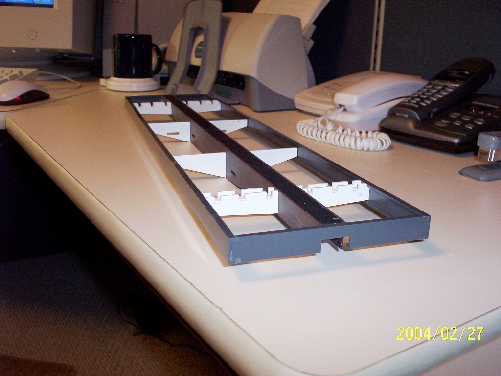
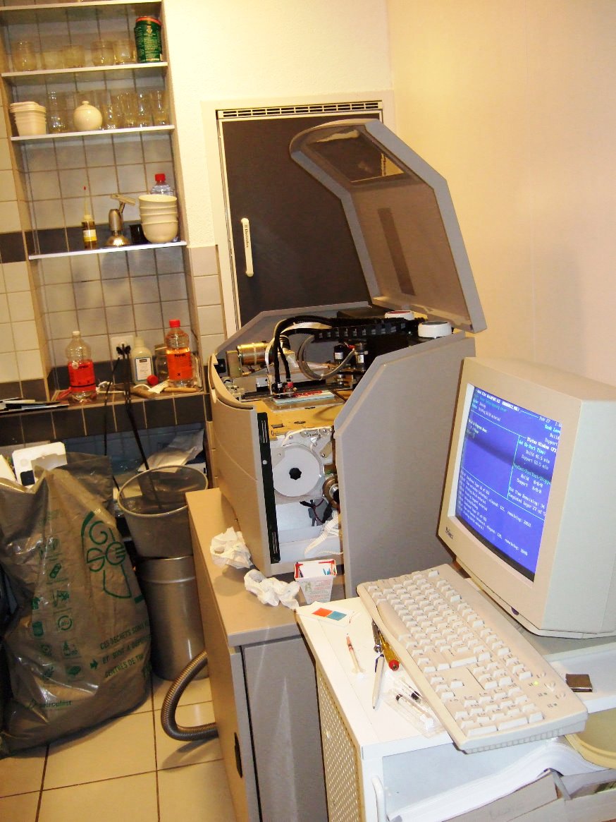
I should probably admit that the methodology I use for making small batches of stirrup steps is probably inaccessible to most other modelers; and maybe with a bit more patience I could have come up with acceptable results from bending and forming brass bar stock, but my technique is to cut stirrup steps out of solid brass sheet (of the appropriate thickness) with my Japax wire EDM. What is wire EDM? It's computer driven magic--think of an electronic bandsaw where a small current of electricity is used instead of a blade to literally burn metal from a workpiece within a few ten-thousandths of an inch, all guided by a computer, and that's wire EDM. Pretty much if I can drawn it in CAD, then I can cut it out of any conductive material. Stirrups steps so formed have tight "bends" and fit perfectly--and being made out of brass, they're a lot tougher than cast white metal ones. Of course, they also need to be drilled at the proper location of the strap so as to attach to the bottom or side of one's car; and so I set up a special drilling jig in my mill-drill for this job, also cut on the wire EDM (see pics at upper right). For securing stirrup steps to the cars, I use Phil Dippel's (a.k.a Phil's Narrow Gauge) exquisitely formed square head brass pins. |
|||
|
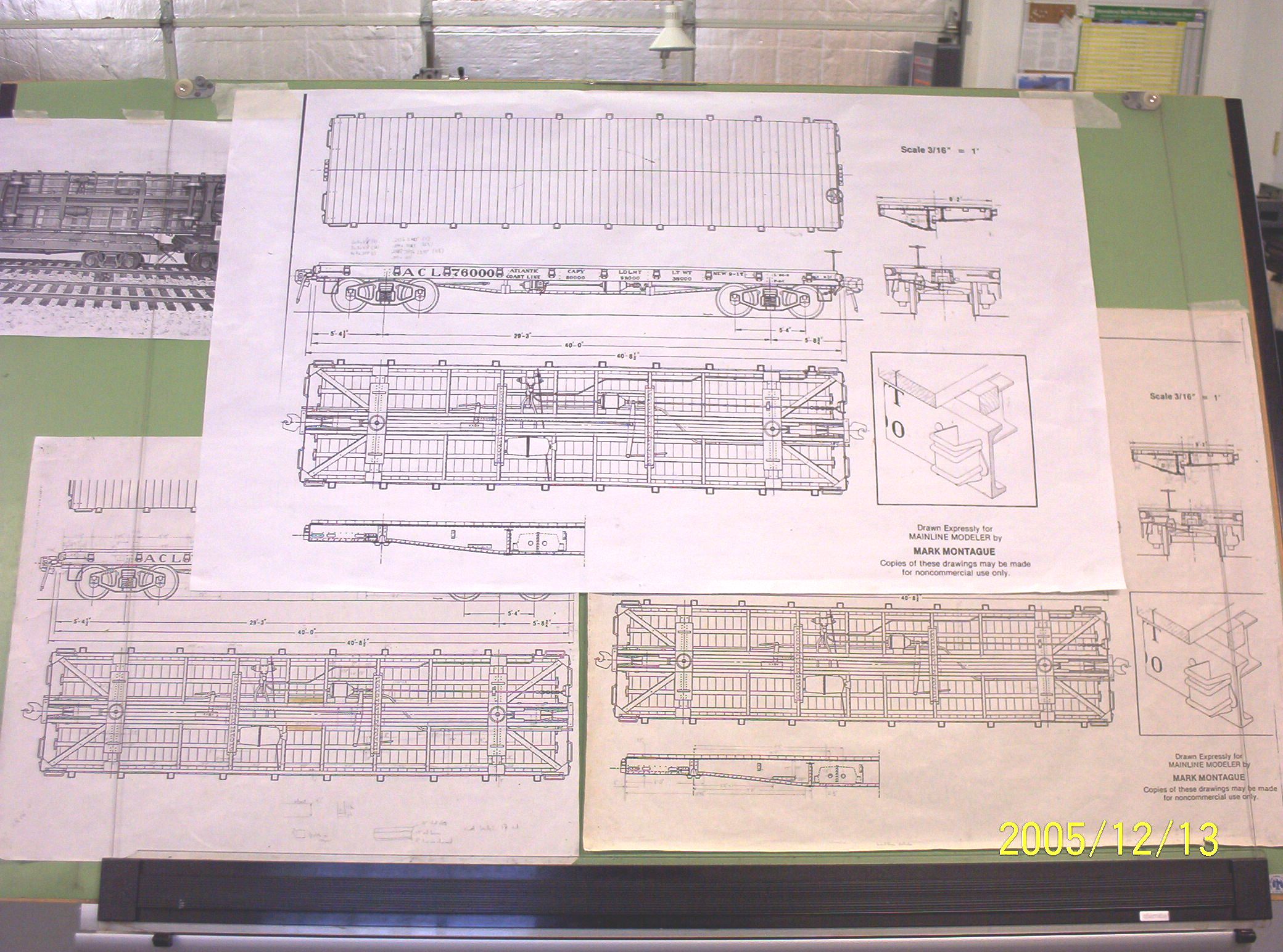
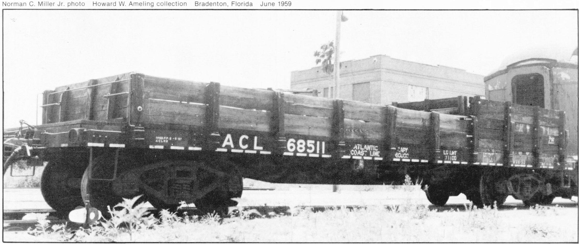
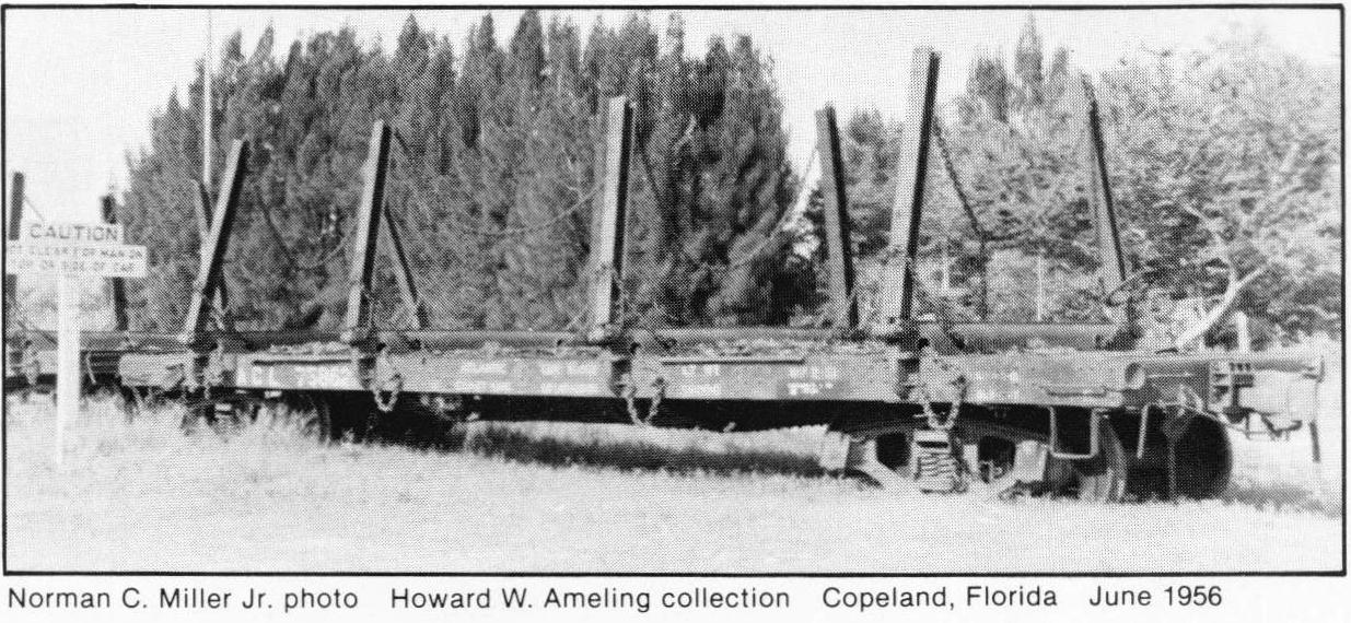
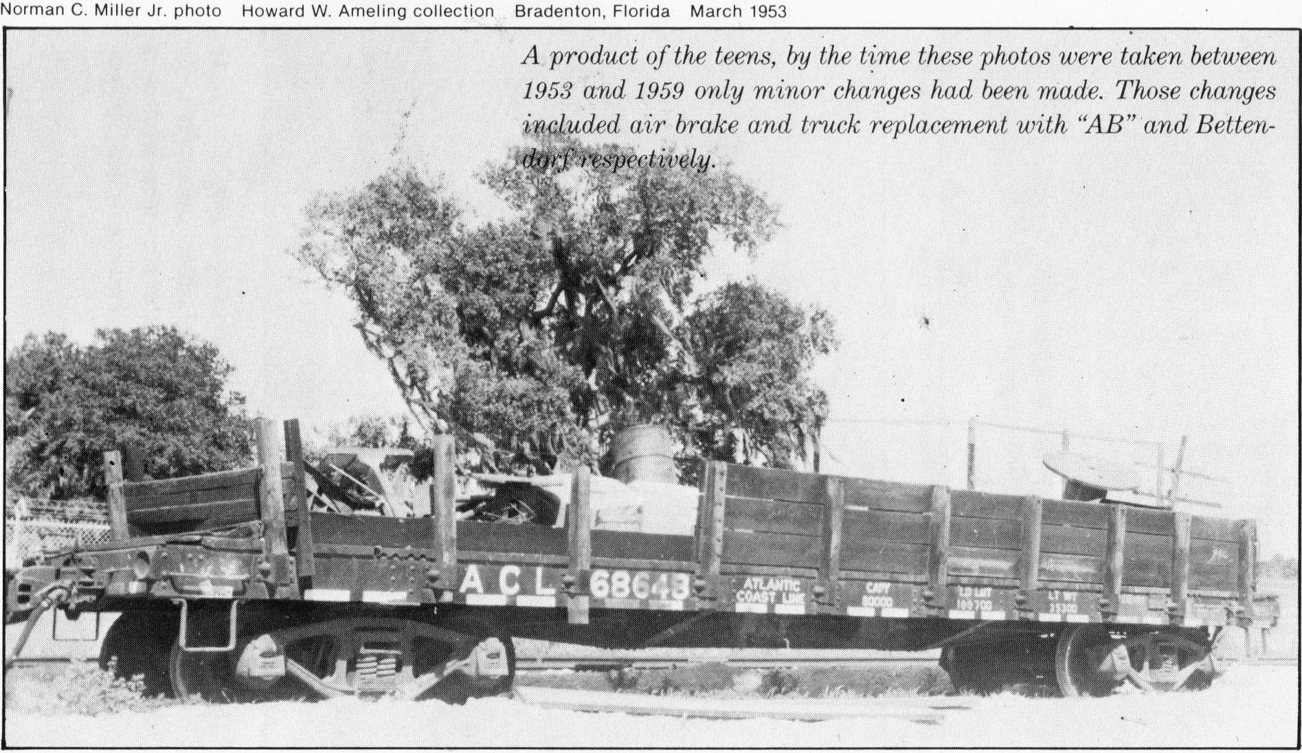
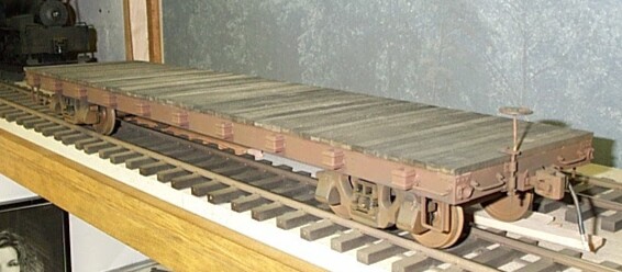
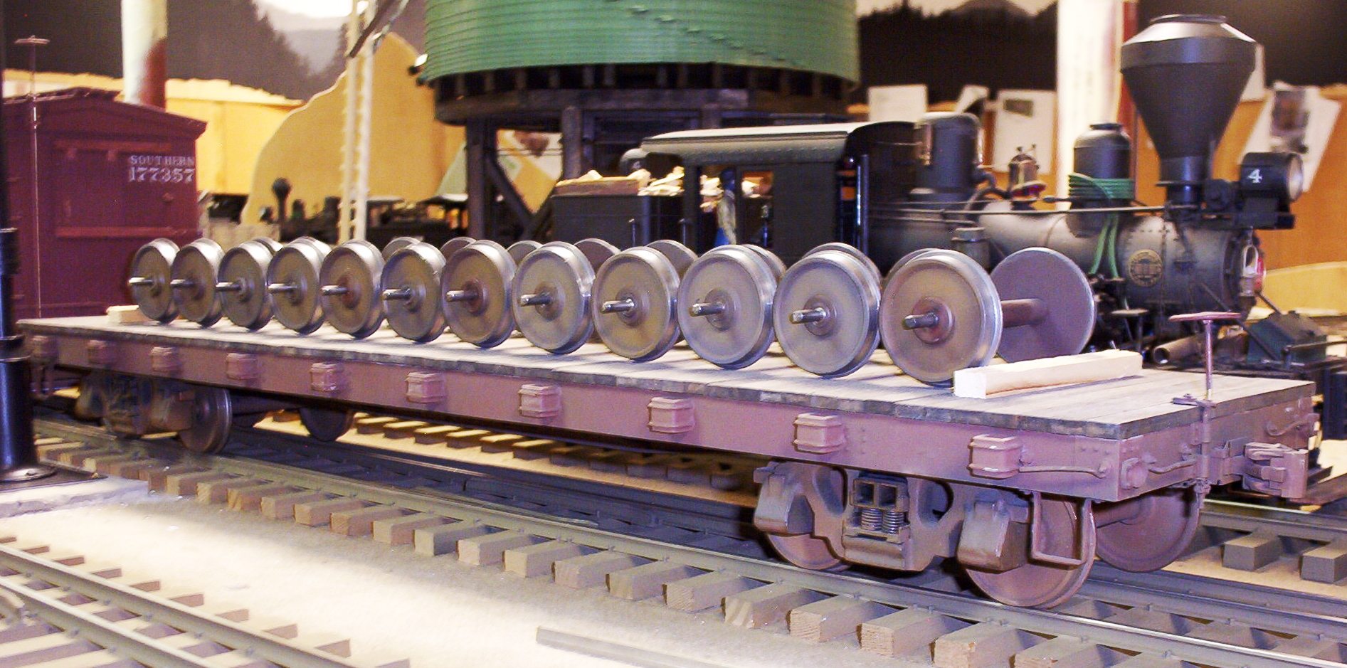
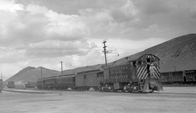
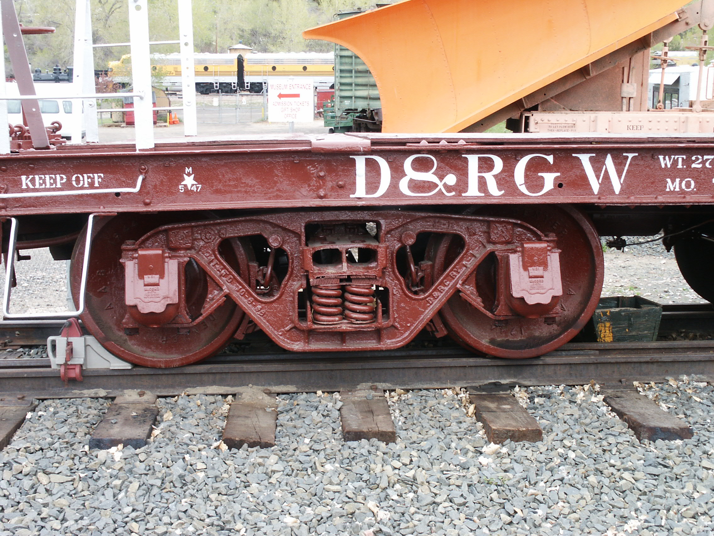
The AC&F 40' flats were work-a-day utility vehicles built for many roads. The Mainline Modeler article which was the genesis of these models focused on a series of cars built for the Atlantic Coast Line, but similar cars could be found plying the rails of the D&RGW (note the narrow gauge equipment atop the standard gauge flats, below) and other lines wherever a platform car of modest capacity was required. Given the Bettendorf T-section trucks which originally equipped these flats, and the lack of fishbelly sides sills to compliment their sturdy built-up fishbelly center sills, these were roughly 80,000 lbs capacity cars. I originally chose this prototype because, well, the plans were available and it looked relatively simple. Once again, my thanks go to you, Mr. Hundman, the publisher of Mainline Modeler, and to Mark Montague, the article's author. Photo Sources: The Best of Mainline Modeler's Freight Cars, Vol. 3 (drawing & ACL pics), Denver Public Library, Western history collection (D&RGW pics).
The First Standard Gauge Flat Car In F Scale
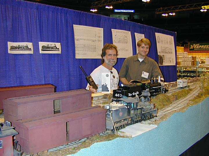
And The Real Builder Is . . . Well, not too hard; and here, I must give credit where credit is due: The first F scale standard gauge flat was put together, not by me in my Knoxville, TN workshop, but at the 2001 NMRA National Train Show by my dear wife Helen using leftover Gauge 3 parts! To be candid, Helen is also a much faster riveter and handlayer of track than myself; and I don't think our booth could have had a better advertisement for F scale, certainly not a more attractive one, than her, especially compared to those two goons above. The First Standard Gauge Freight Car Truck in F Scale
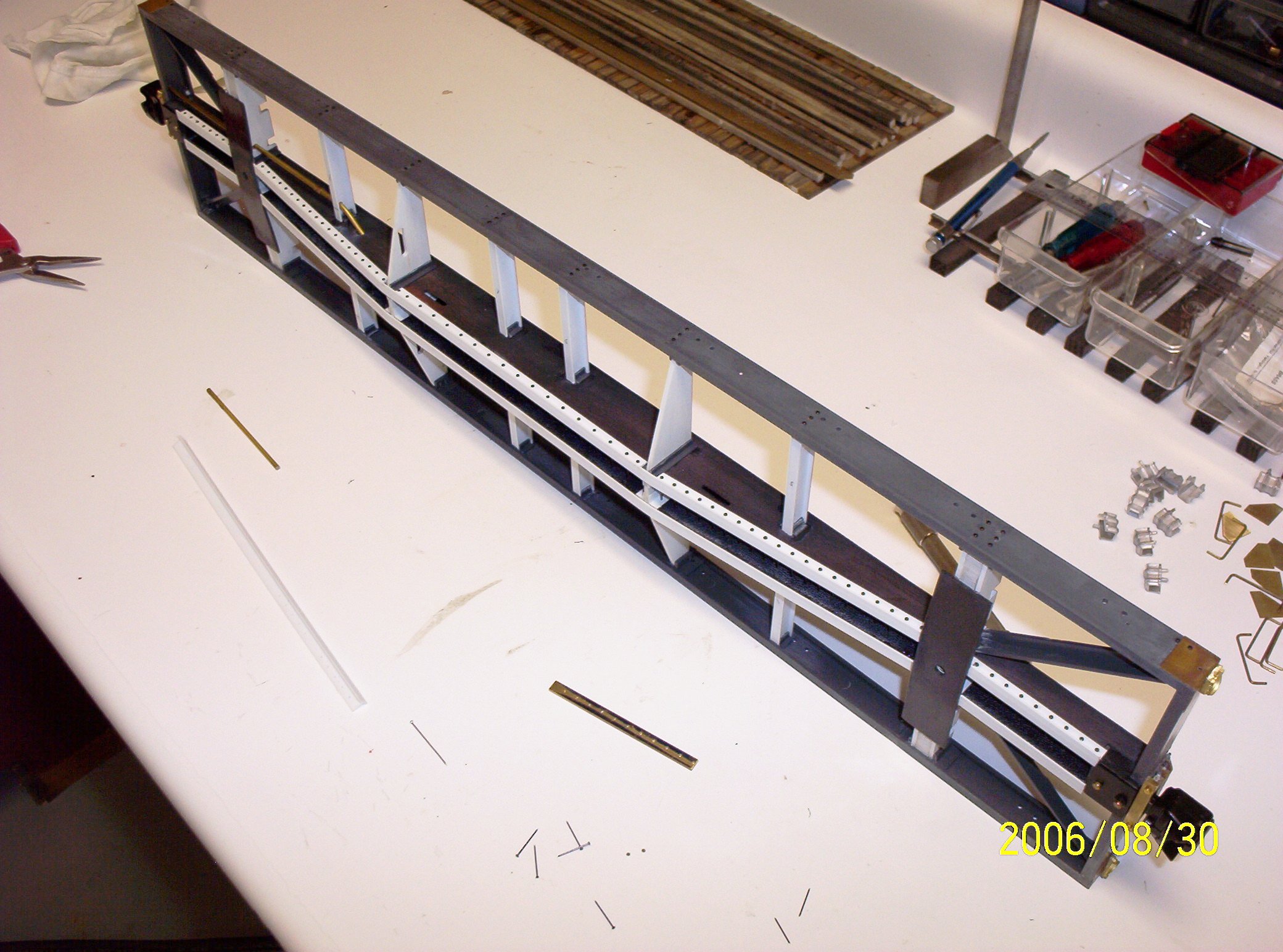
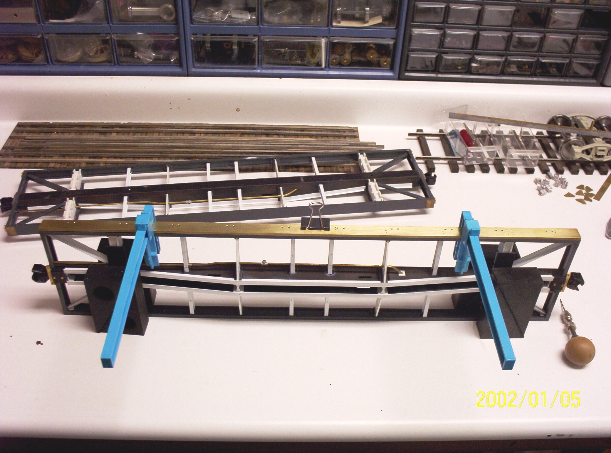
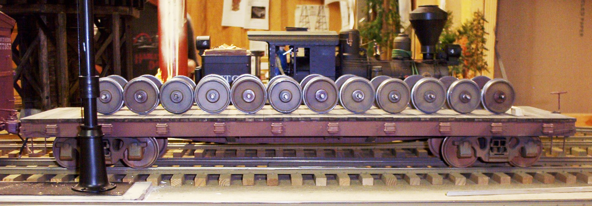
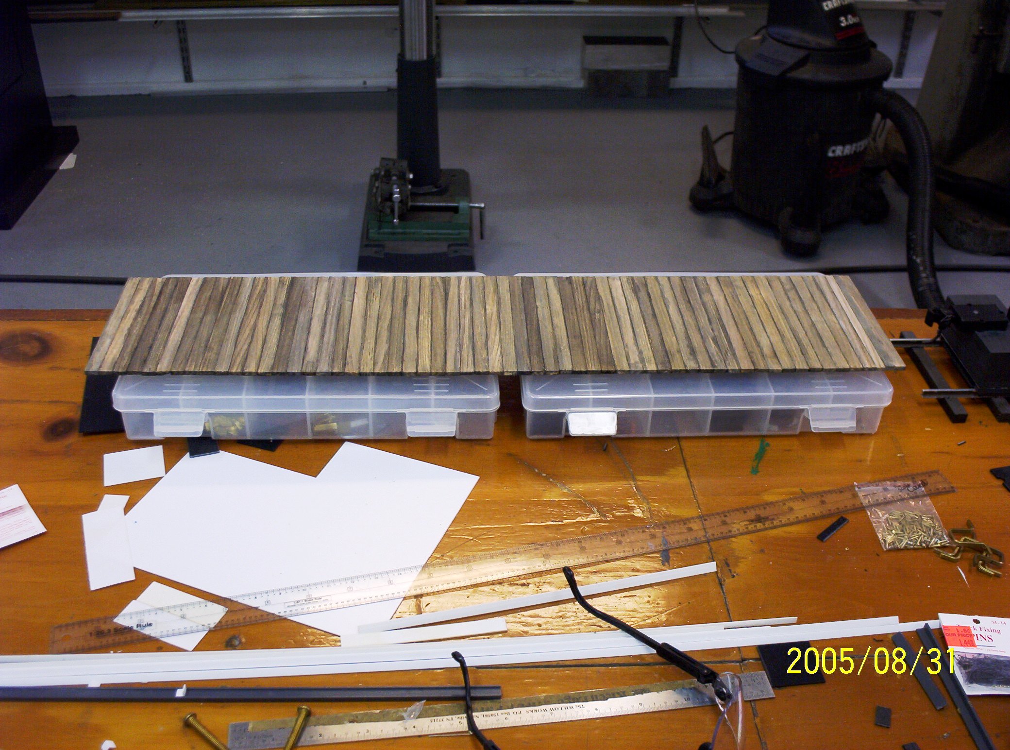
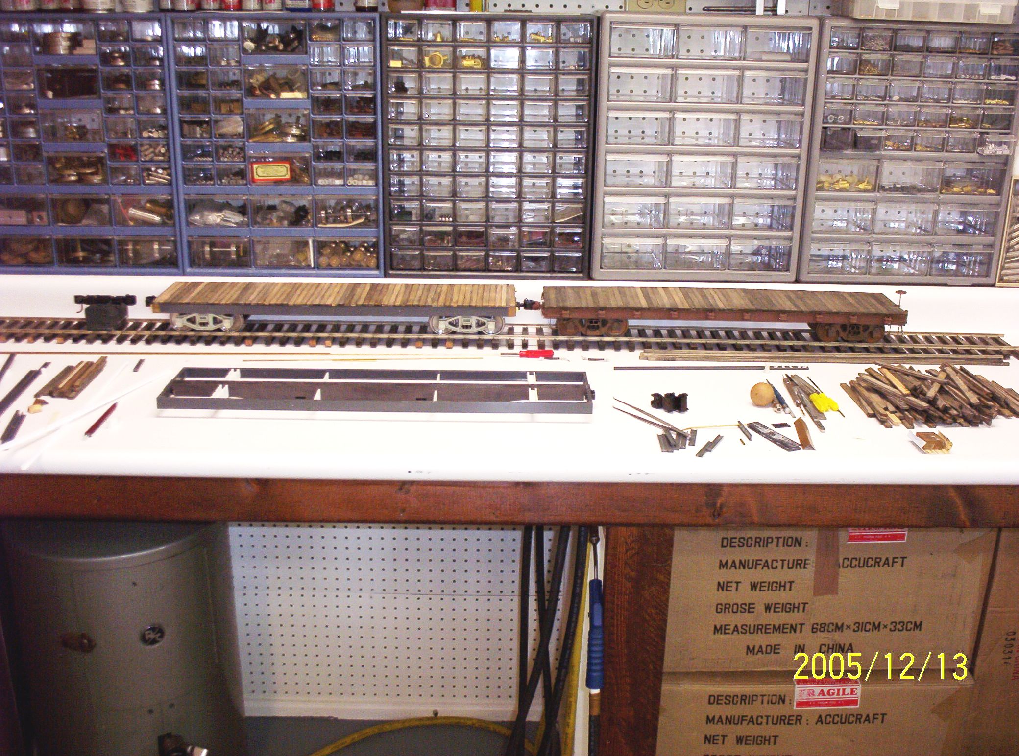
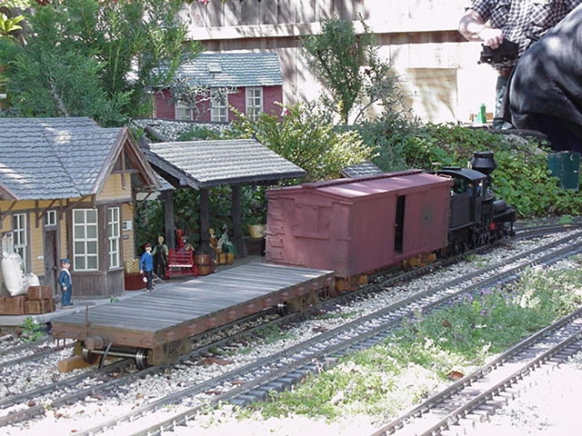
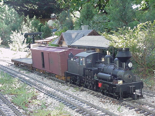
The Completed Car This first car was made for the most part like the two subsequent ones below, using .060" ABS sheet cut to simulate the fishbelly center sills and 5/8" Plastruct channels to represent the prototype's 10" side sills. A smattering of additional Plastruct Ts, channels, and angles complete the underframe. Kadee "G scale" couplers were used along with the usual assortment of commercially available white metal detail parts. The deck is basswood, stained with a wash of alcohol and India ink, and then distressed with a file card. The deck boards were glued with Titebond II carpenter's glue to their stringers. The trucks and frame were painted and weathered separately by my friend Don Niday (who now owns the car). A load of 33" Gauge 3 wheelsets is pictured with the car below on Don's dual gauge indoor railroad, The Crofut & Iron Creek.
Cars #2 and #3
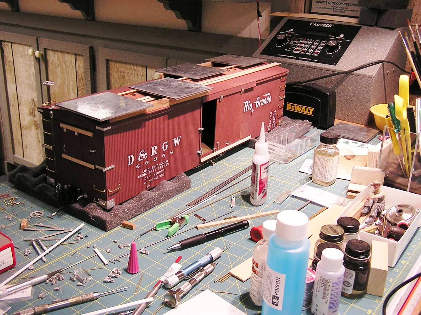
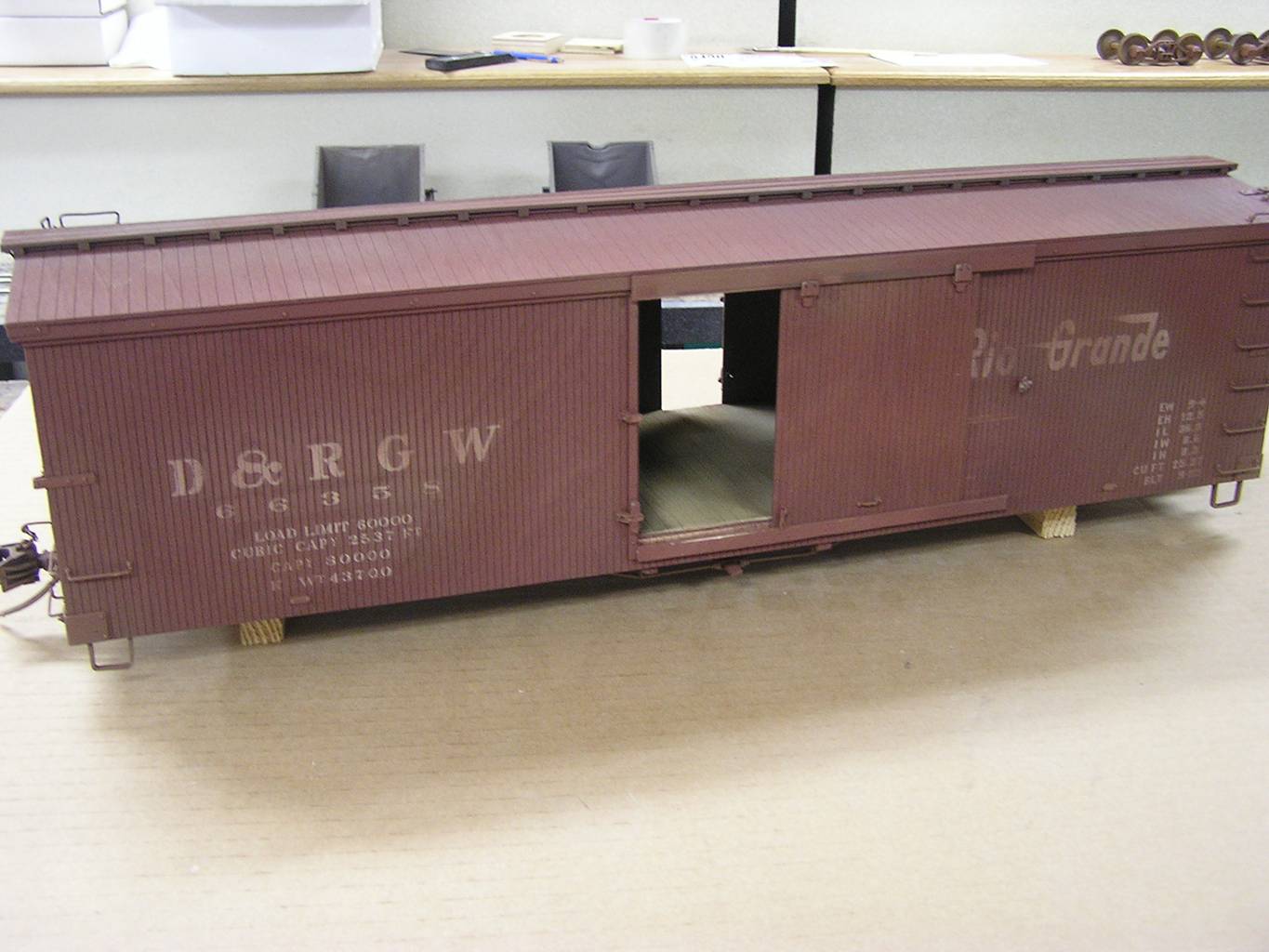
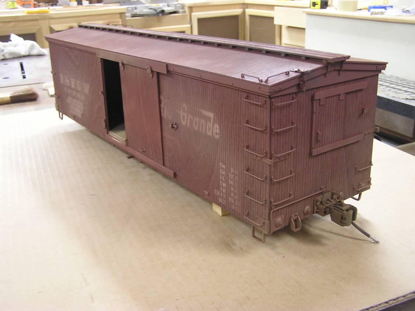
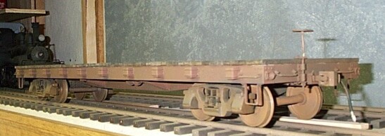
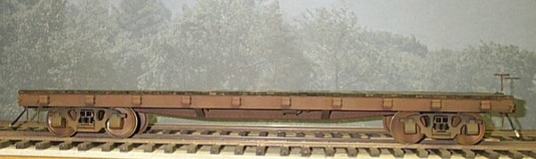
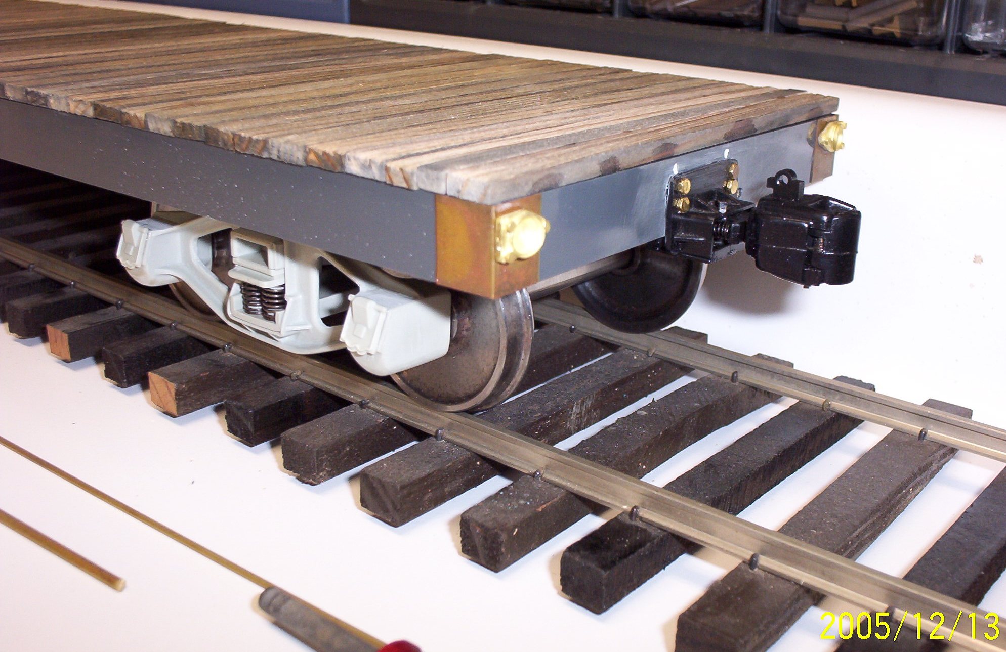
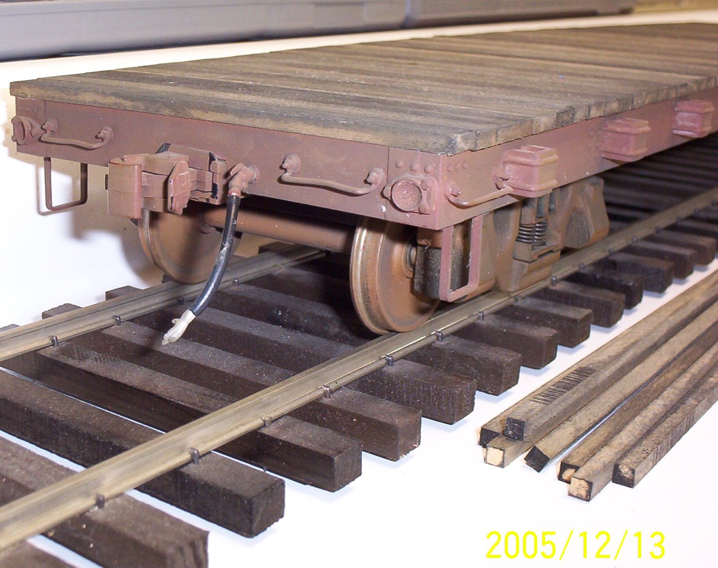
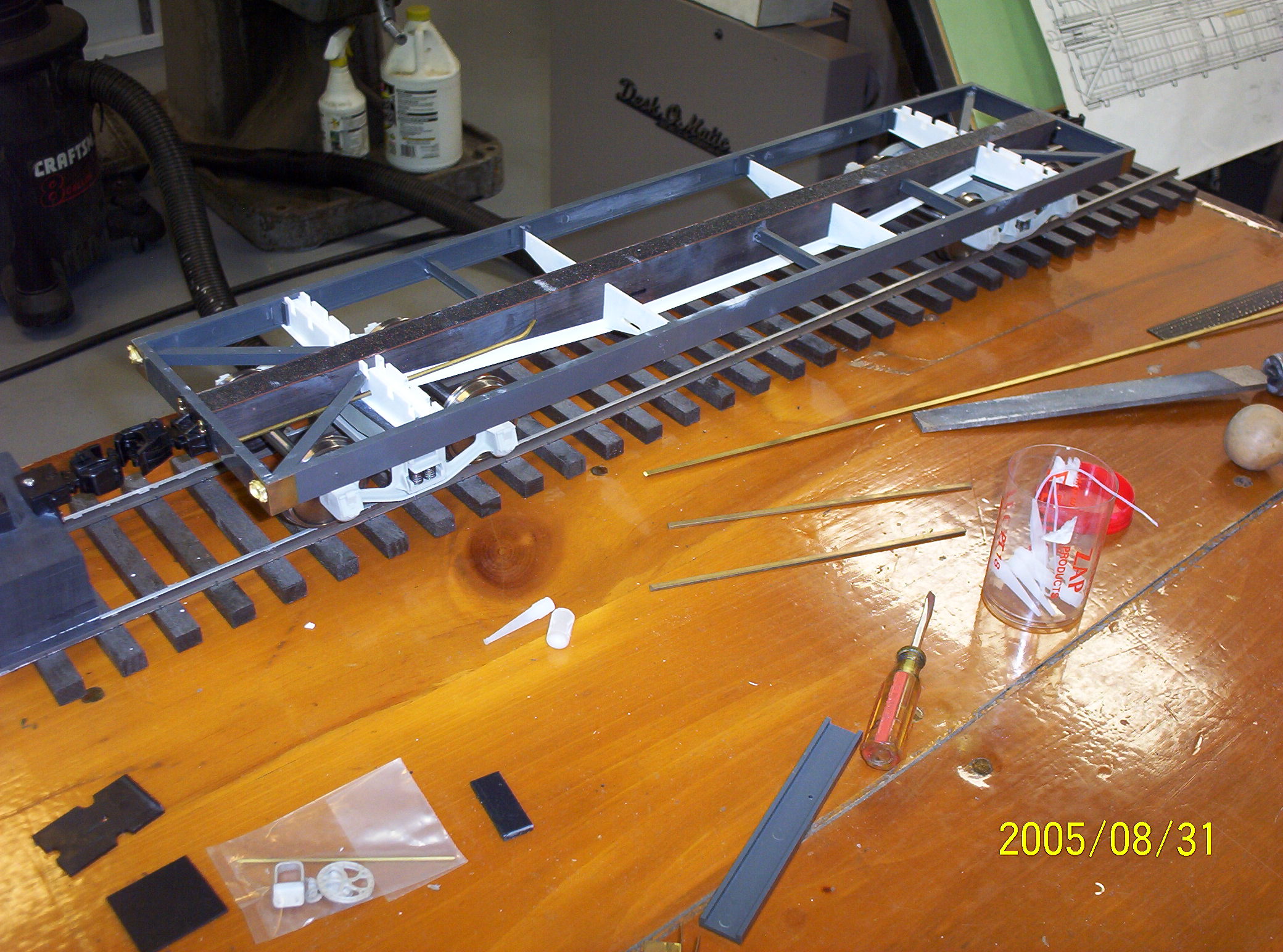
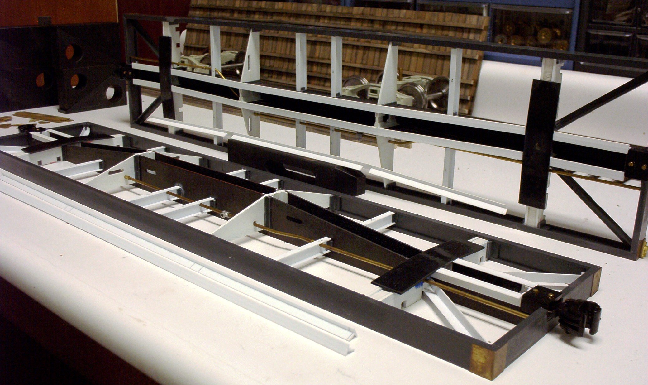
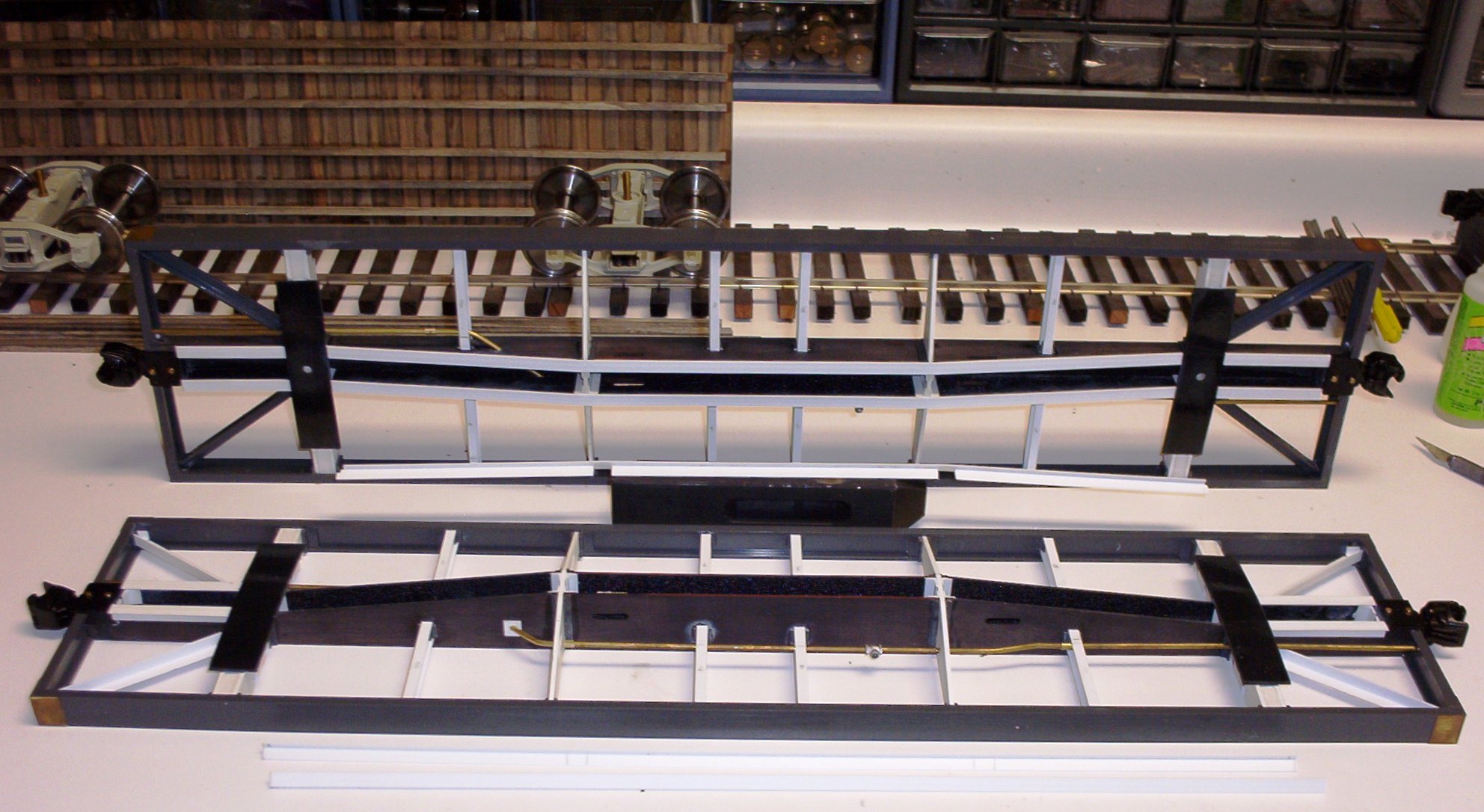
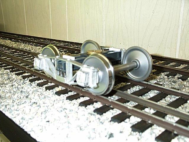
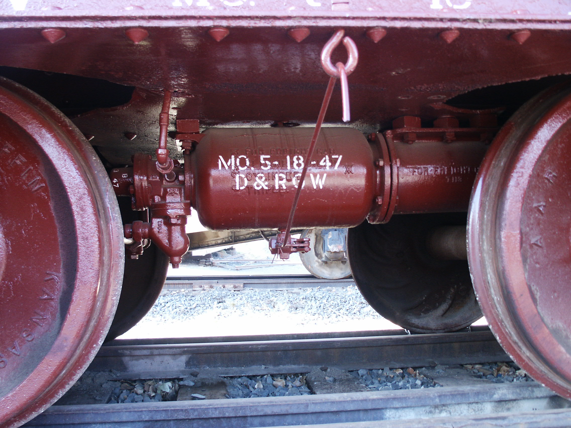
These next generation cars were built using the same ABS sheet, milled or filed to shape, and Plastruct channels as the earlier Gauge 3 cars, but with a few added refinements. First, the trucks actually are Bettendorf T-sections, patterned after the original equipment used on these cars, though subsequent shopping replaced the prototype ones with stronger u-section designs. I have Mr. Bob Uniack to thank for these 1/20th scale cast urethane trucks. Around 2004 or so, Bob began work on an F scale Southern Pacific B-50-14 outside braced boxcar, having already built several 1:32 scale models of the same car (you can view more of his work here). Bob made styrene patterns for these unique, early cast steel trucks based upon drawings published in Mainline Modeler and upon his own measurements of the real McCoy--and he was kind enough to share urethane copies with me. Bob used my 33" plain steel wheelsets along with Hartford Products large springs to complete the trucks.
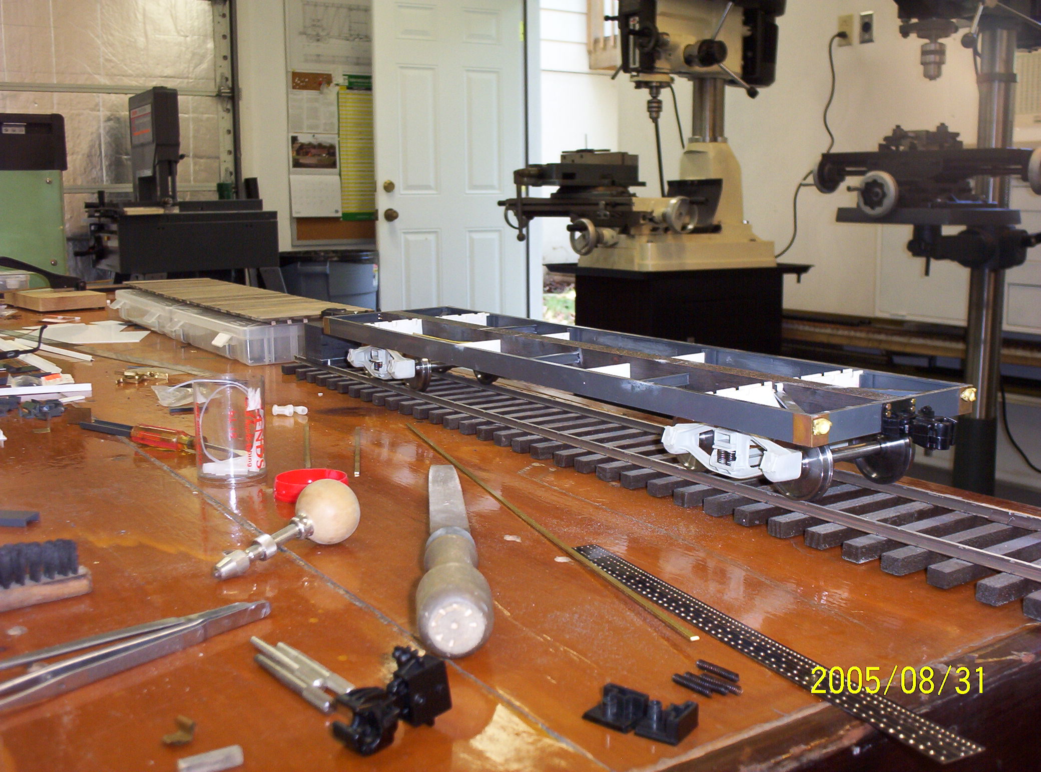
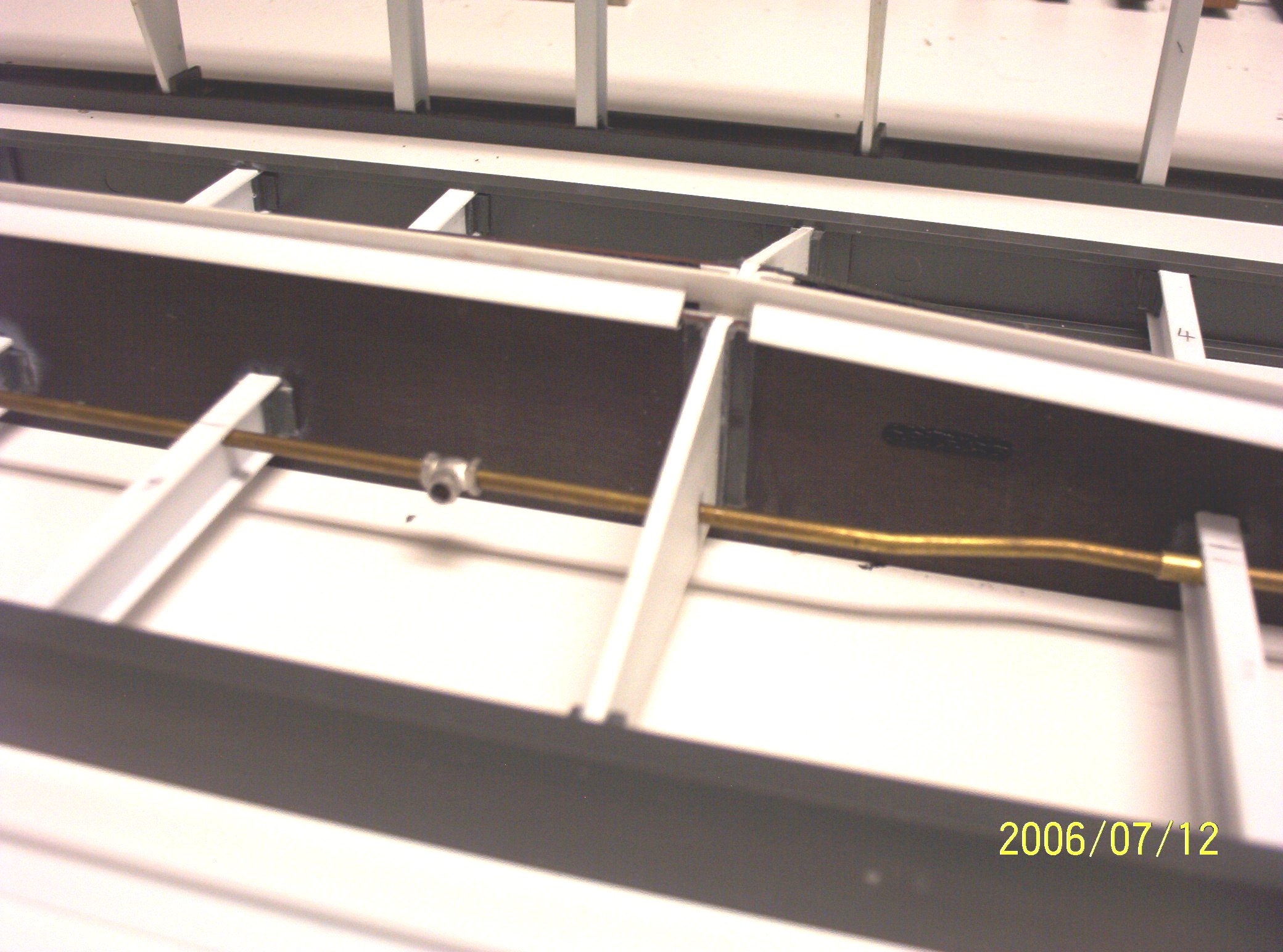
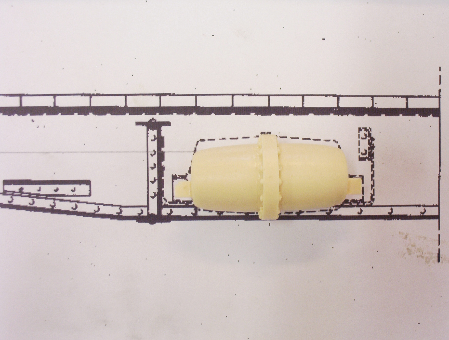
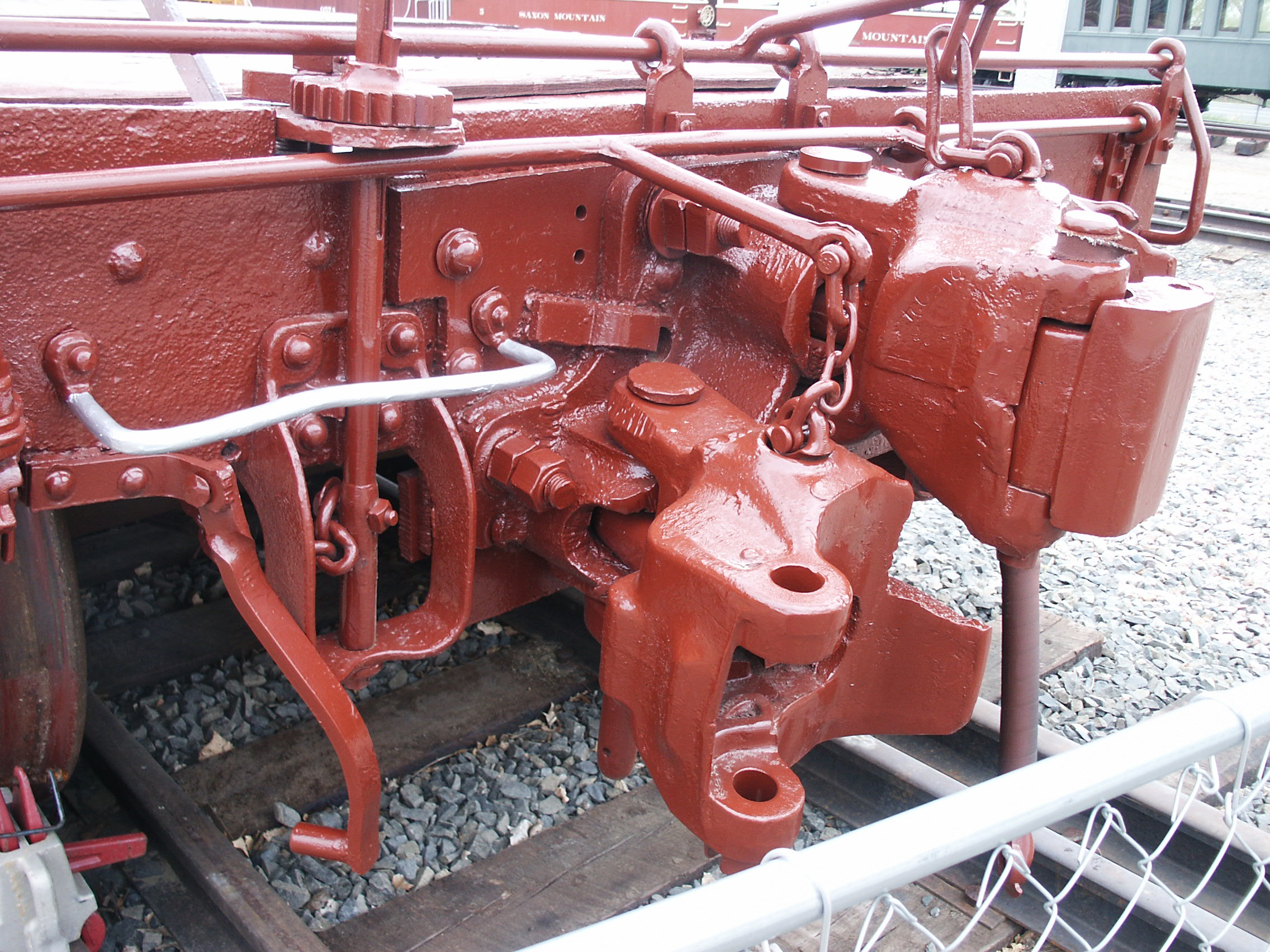
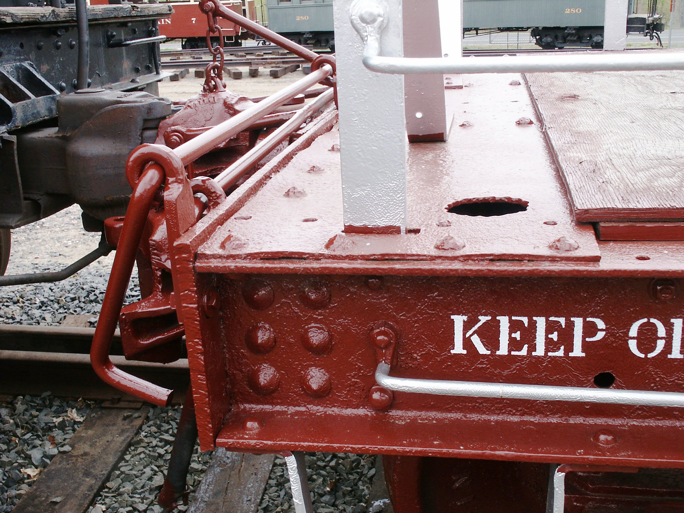
At some point, every large-scaler is faced with the question of what brand of coupler to use on his rolling stock, and in particular if he needs to replace the stock commercial couplers he received on his ready-to-run models with something better looking or more reliable. For my Gauge 3 models, I consistently used the earlier Kadee "G scale" couplers since they operate well and look reasonably good, minus their short steel uncoupling pins which look vaguely like an air hose minus its glad hand (these I usually cut off, destroying of course their delayed action uncoupling feature, which would never have worked anyway given the coupler center height requirements in Gauge 3). For the initial F scale flat, I had again used Kadees; but in 1/20th scale, they are perhaps a little undersize--plus--I wanted a coupler that could utilize a functional uncoupler lift bar. And here, Accucraft had the right injection molded plastic product, except for one thing: The Accucraft coupler, being intended for use on tight radius, narrow gauge curves, has a long shank which is pivoted from the vary front of the Accucraft draft gear box. The solution was to discard most of the Accucraft draft gear box's molded-in striker plate, and create my own from brass. The end result is a coupler with less exposed shank and a more prototypical looking striker plate, soldered up from brass bits and pieces, most of which were cut on my wire EDM. Construction Pics Below are various views in the construction of these two cars. As you can tell from the dates, this has been an on-again-off-again project over the last several years. My thanks go to my friend Barry Bogs for the AB brake system triple valve casting and for copies in urethane of the AB reservoir I originally made for Gauge 3. This batch of photos basically brings us up to mid-2007.
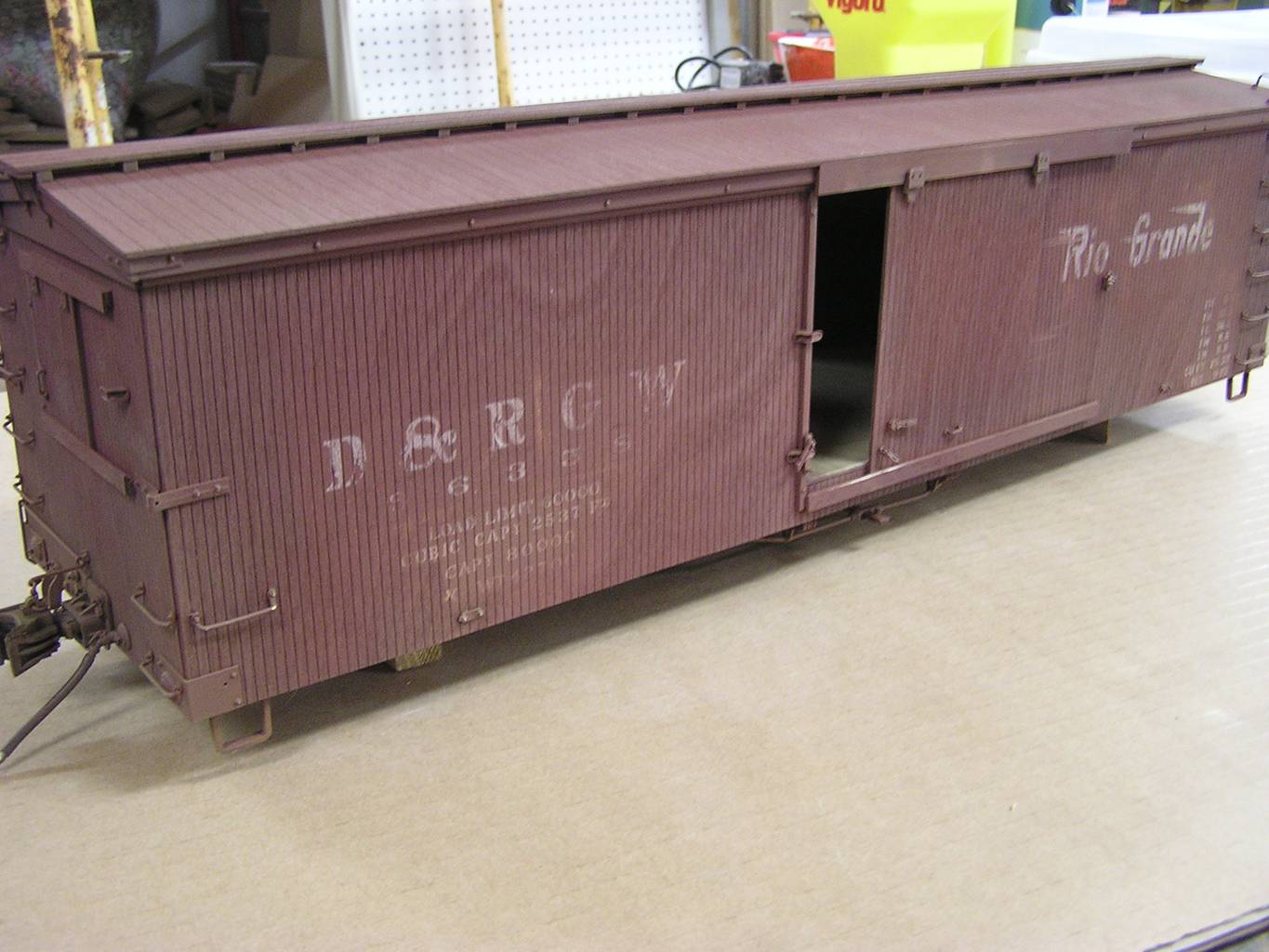
The Completed Cars (To Be
Continued--last update 10-14-09) |
|||
|
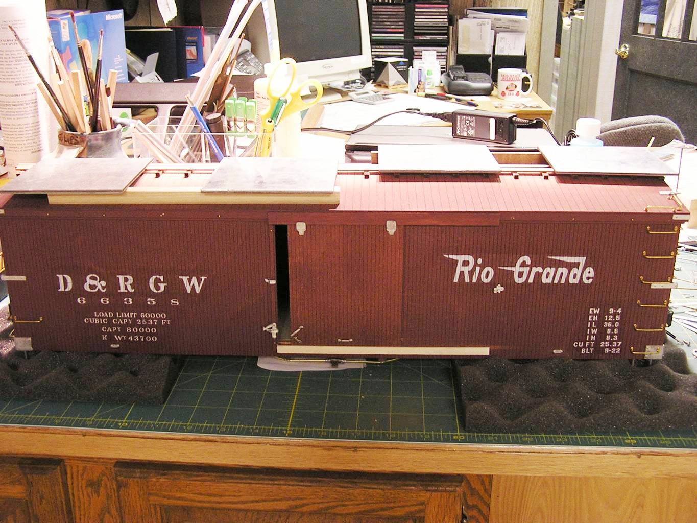
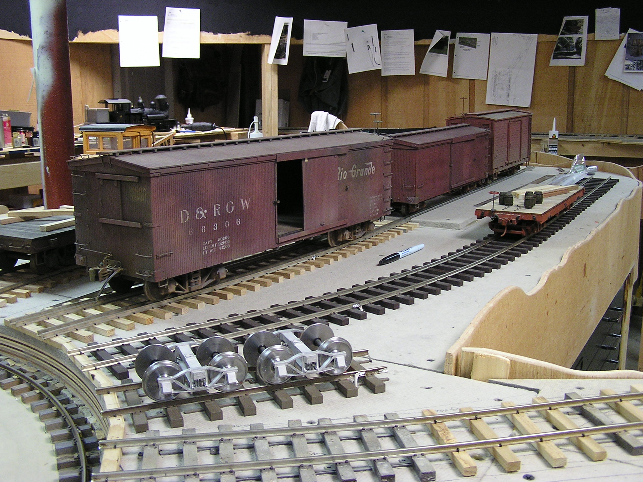
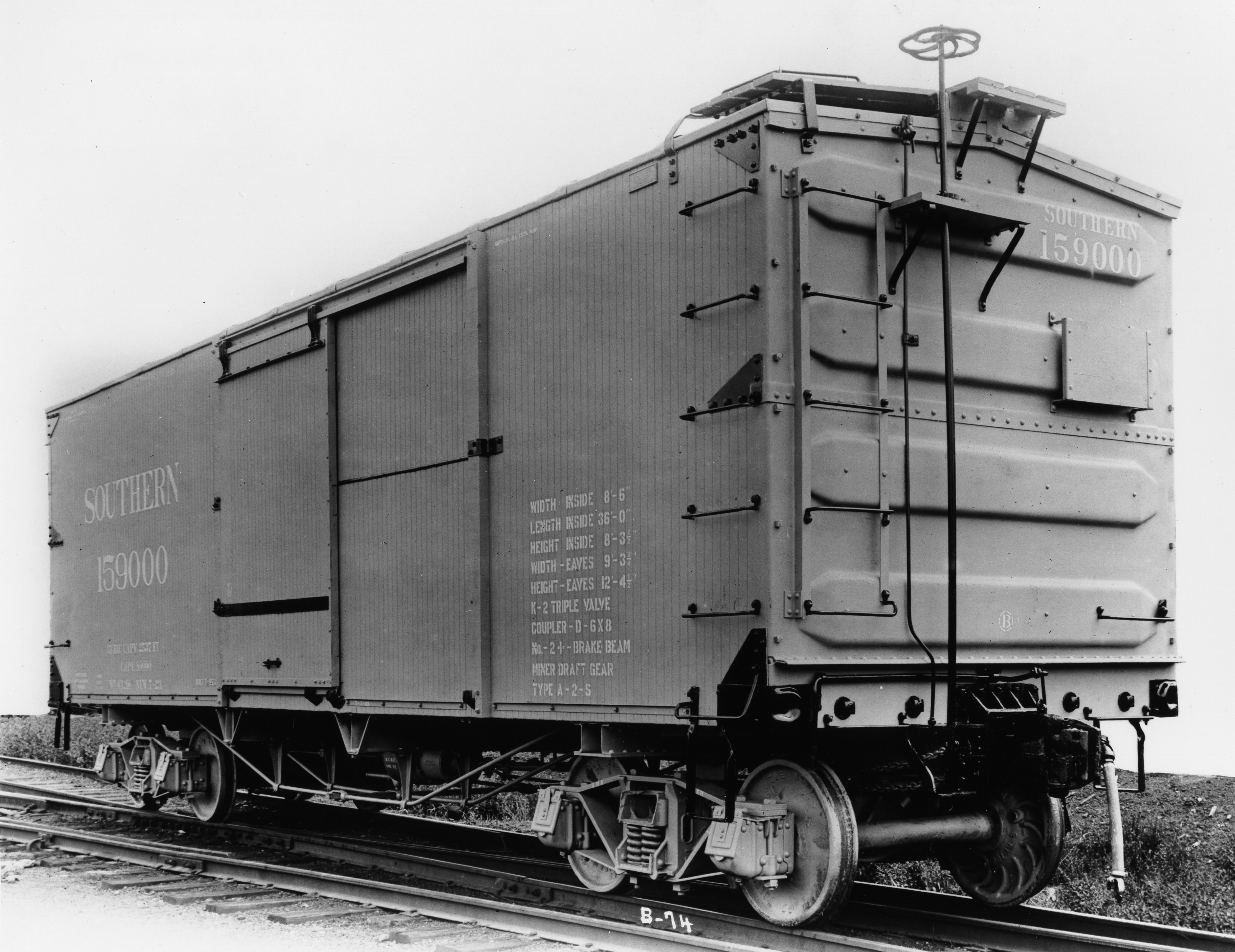
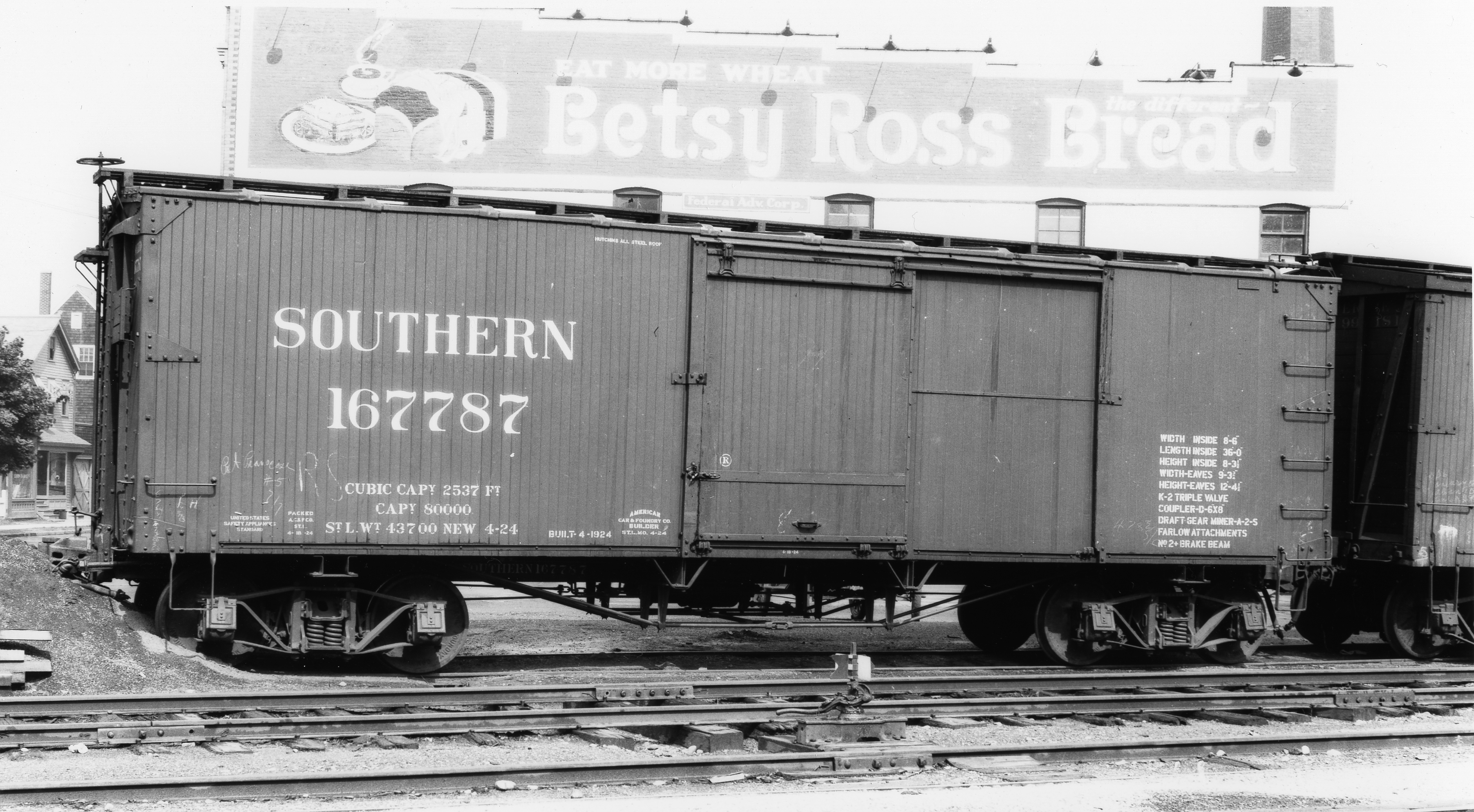
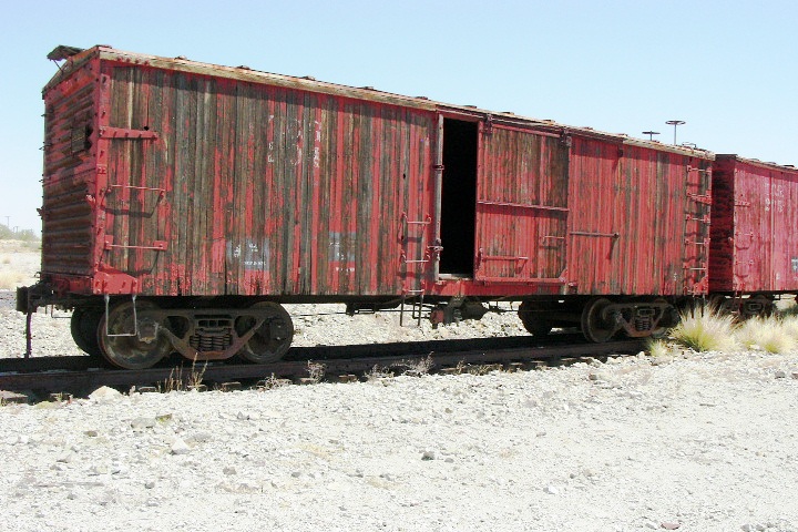
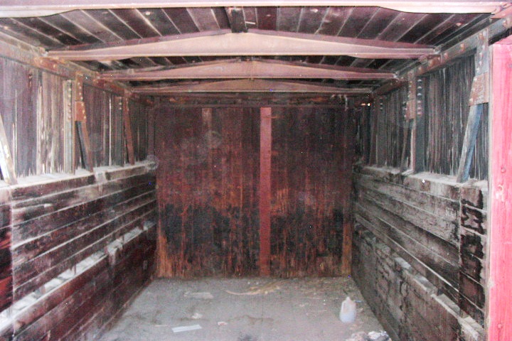
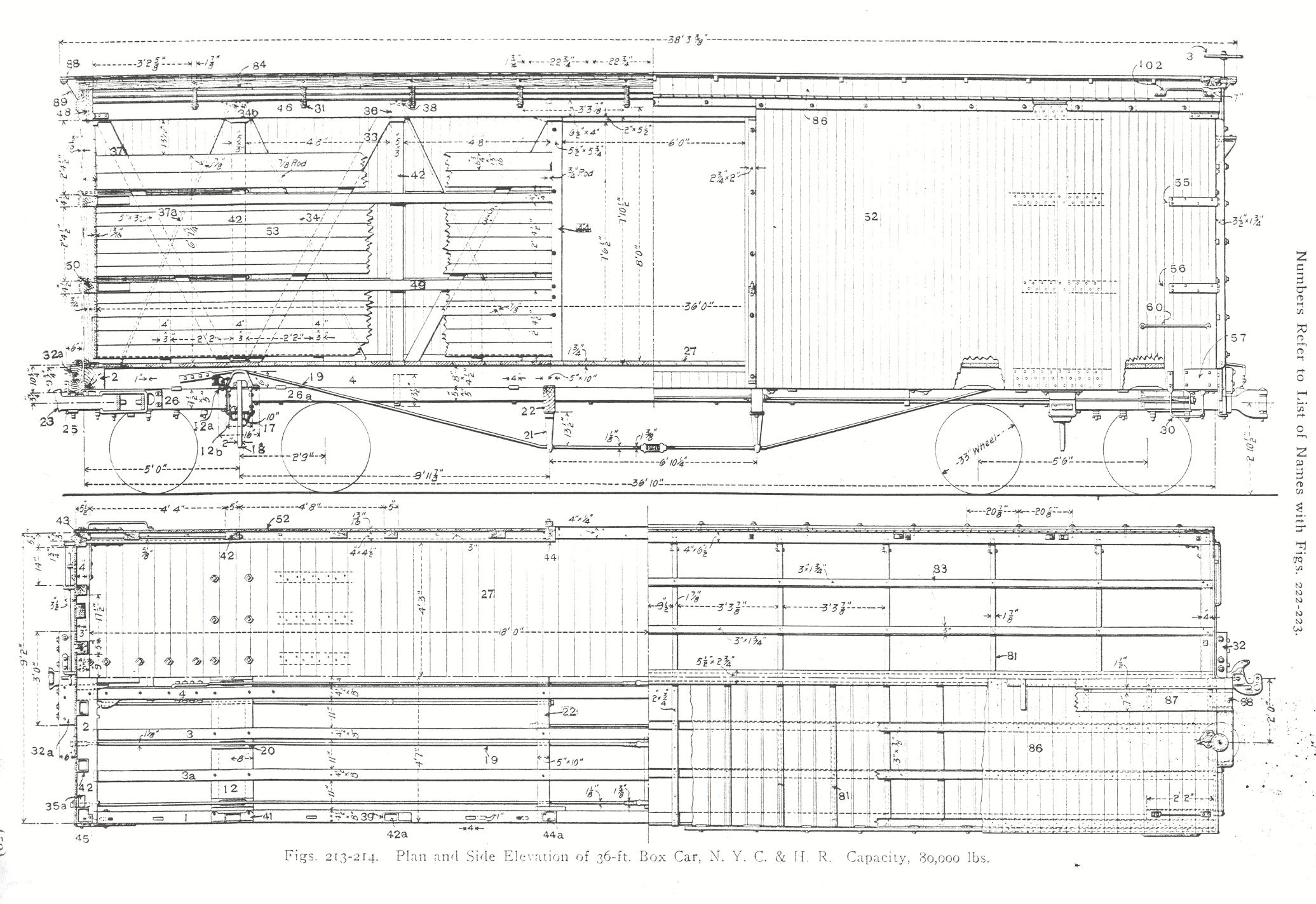
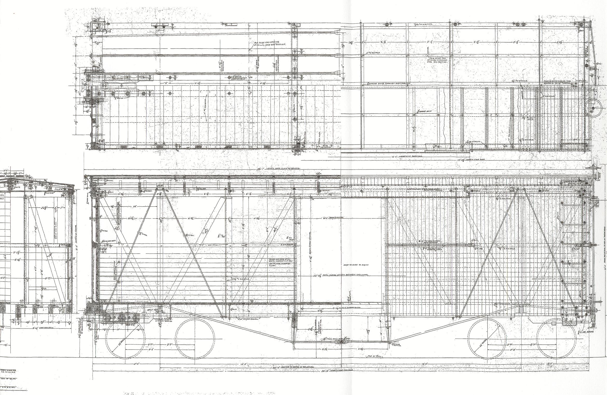
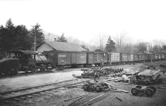
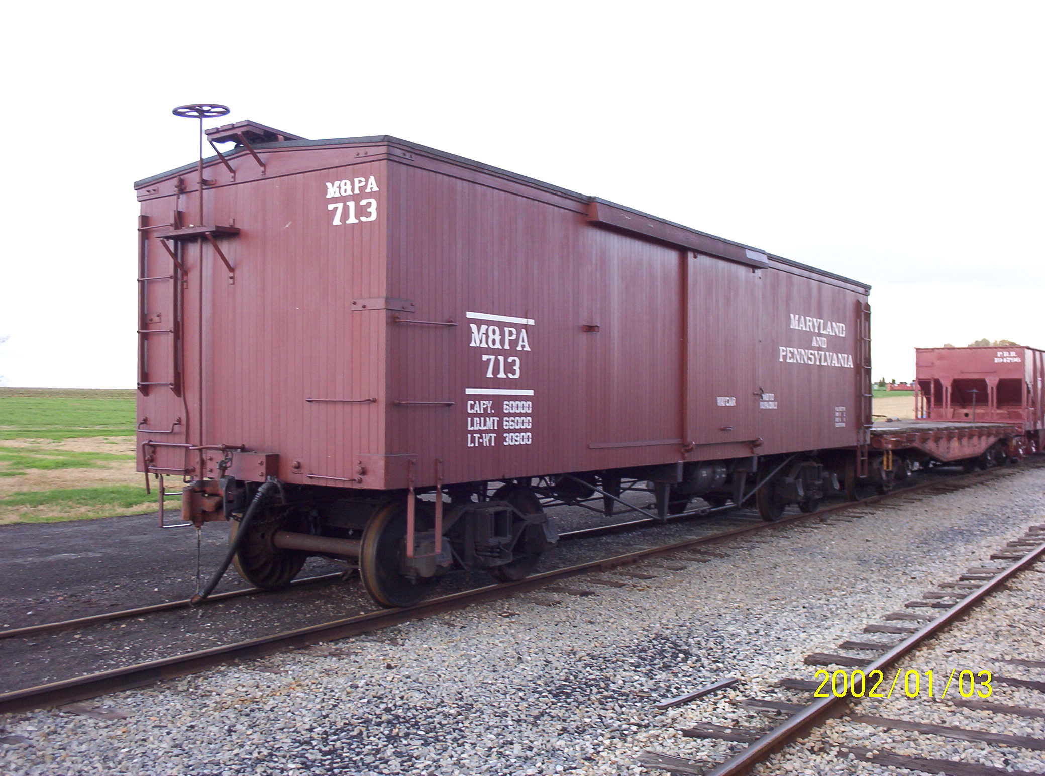
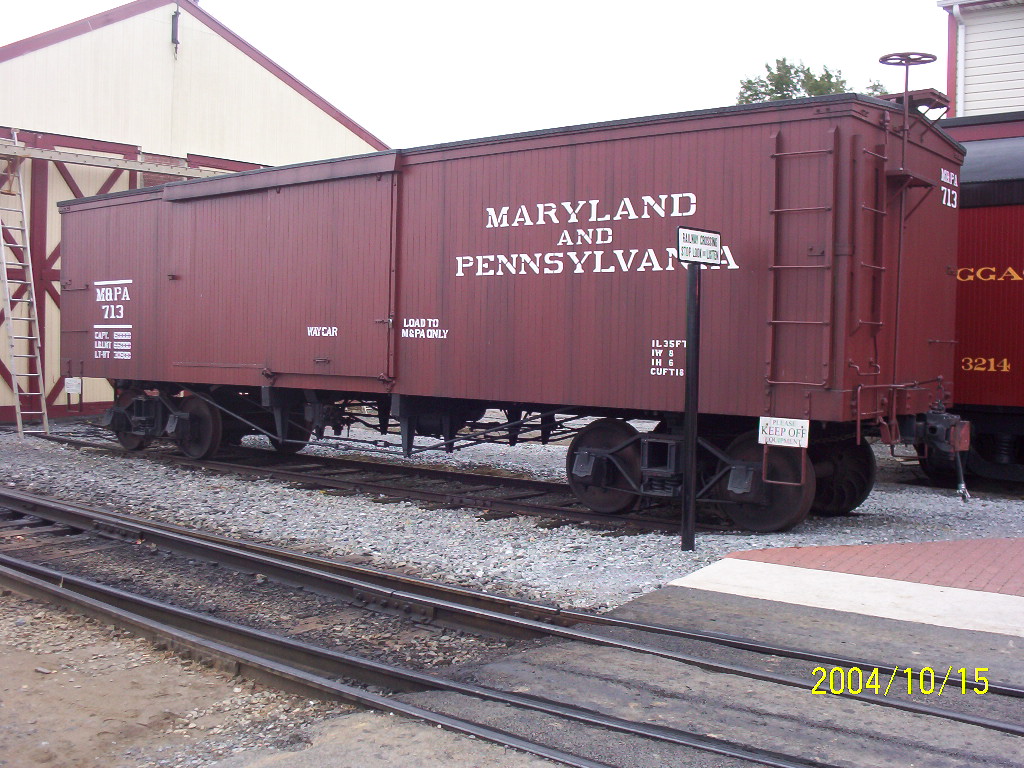
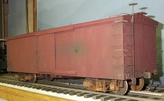
The 36' foot wooden truss-rod boxcar was a staple of late 19th and early 20th century railroading. Some of these ubiquitous house cars survived into the late steam era in maintenance-of-way use, though cars with archbar trucks and wooden underframes had long since been outlawed from interchange service. A very few examples survived into the preservation era (the Soo Line car at right, for instance, at the Mid-Continent Railway Museum), but the number of truss-rod equipped standard gauge wooden boxcars still in existence can be counted on one hand. These wooden truss-rod cars are to be distinguished from their close cousins, the composite cars built between 1900 and the end of wood car construction in the 1920s. The distinguishing factor here is the greater use of steel in the composite cars, mainly in terms of steel underframes and the frequent application of pressed steel ends. These sorts of cars are much more common in preservation and fall into two basic categories: the double-sheathed cars and the single-sheathed designs, the latter being readily distinguished by their exposed "outside" steel bracing. For instance, the USRA 40' single-sheathed boxcar and the Fowler outside braced design (and Fowler clones such as the D&RGW car below left) used wood sheathing on the inside of the car in order to protect the cargo--not the carbody's supporting structure--from the elements. In contrast, the smooth sided double-sheathed designs, such as the pre-WWI D&RGW 36' beet boxcars (below right) used wood sheathing to protect both the car's structural framework as well its cargo from the elements, and hence, were "double" sheathed on both sides of their bracing. In either case, the wood sheathing is always protective, not structural in its function (a feature that further distinguished wooden and composite car construction from later steel cars where the steel skin itself is often load bearing, not merely protective of car and cargo!). And then there are the oddities which are really transitional designs between the wood car and the 100% steel car eras. Some roads, such as the Delaware and Hudson, maintained substantial 36' steel underframe, wooden boxcar fleets right through WWII (note the D&H car below at the Railroad Museum of Pennsylvania). Some of these composite designs, while at first glance looking like wooden truss-rod cars, in fact are not, including the odd-ball Southern Railway 36 footers of the early 1920s which used both steel underframes as well as truss-rods (below, center). The D&RGW also had a transitional design built in 1909 which employed a steel underframe, steel interior bracing, and were double sheathed. Subsequent rebuilds of these cars resulted in their wooden ends being replaced with Murphy pressed steel ones. Several examples of these odd 36' composite cars survive, one at the Galveston Railroad Museum and another at the Arizona Railroad Museum (below right). Sadly, none of the offbeat 36' Southern Railway cars survive.
Photo Sources (Left to Right): D&RGW Fowler clone (Barry Bogs); D&H 36' (DQ); SR 36' (Ted Culotta); D&RGW 36' beet boxcar (GRM & ARM websites)
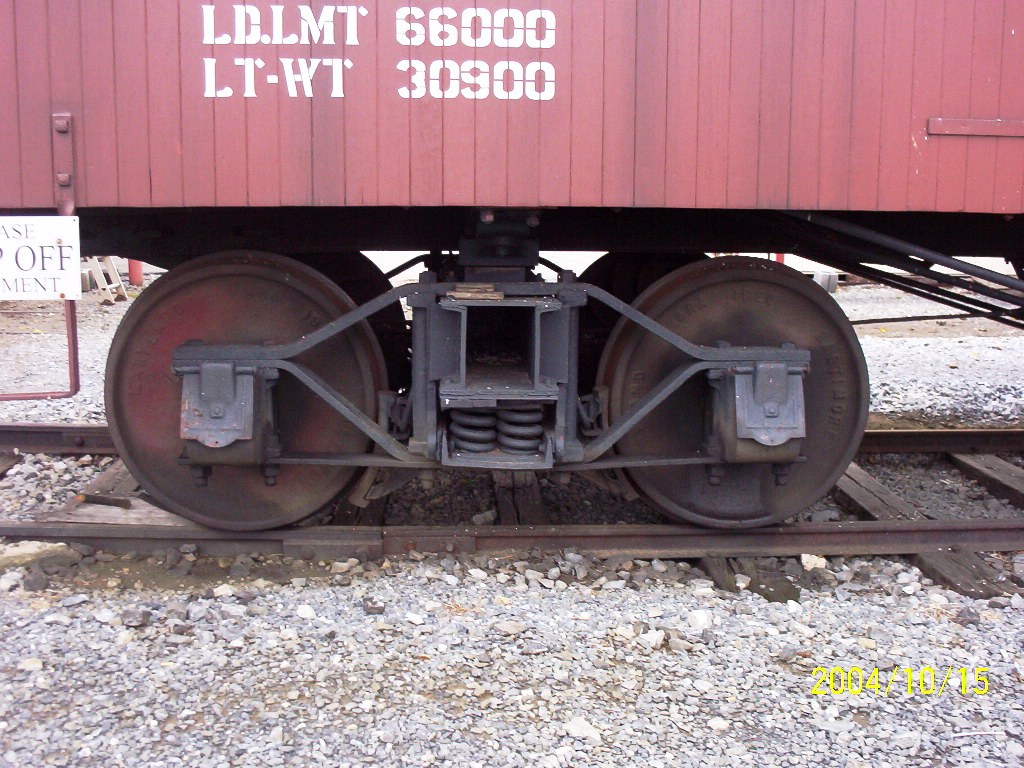
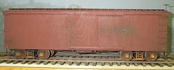
Since at that time I had few machine tools, the trucks I made were an adaptation of some white metal sideframes sold by Mr. Steve King who actually marketed them for Maine 2' gauge modeling in 7/8" scale using Gauge 1 track! With some rudimentary Plastruct I-beam bolsters and Harford Products springs--volah!--the first archbar trucks in 1:20.3 standard gauge were rolling down my test track. Well, as with most compromises, there were, well, compromises; and that was particularly the case here. In F scale this truck's wheelbase is a bit long, about 5'-8", but with nothing else readily available, and a NMRA Convention to display at in July of 2001, this was an acceptable compromise for most parties involved. The results are pictured above.
|
|||
|
Dave's Car (Sold) |
Don's 1st Two Cars (sold)
.JPG)
 |
Don's
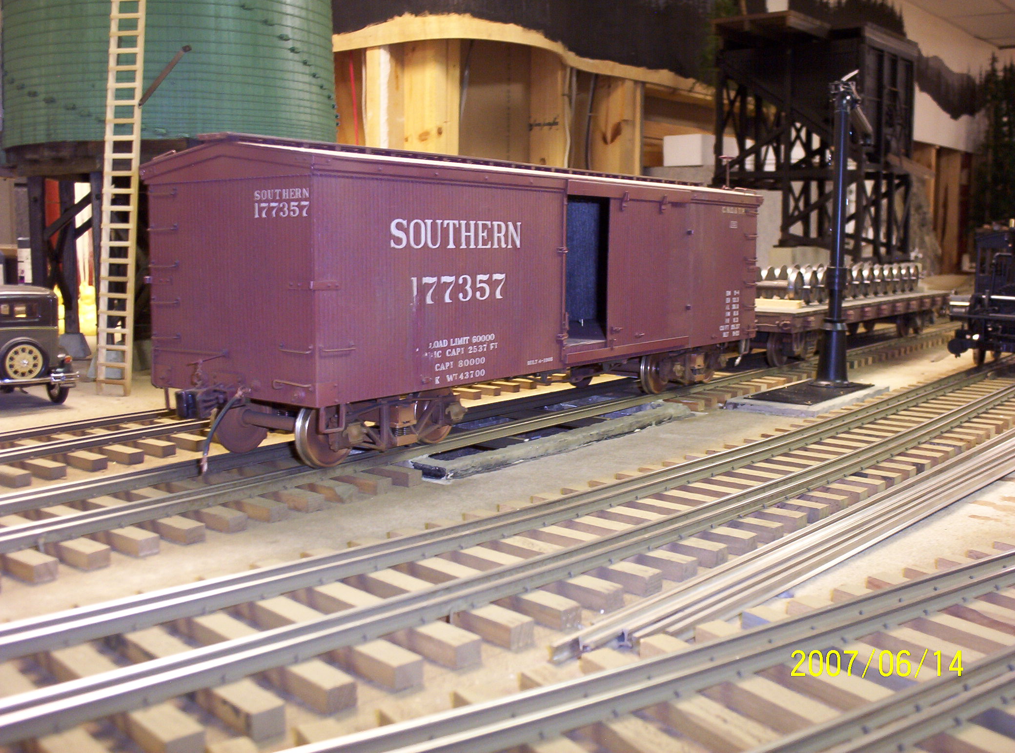
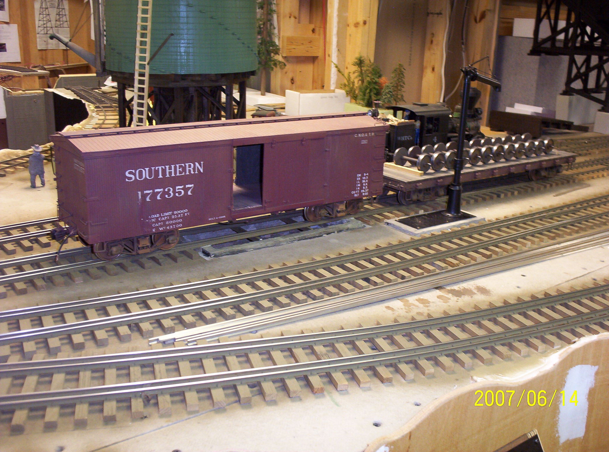
Keeper (w/ SR Reporting Marks)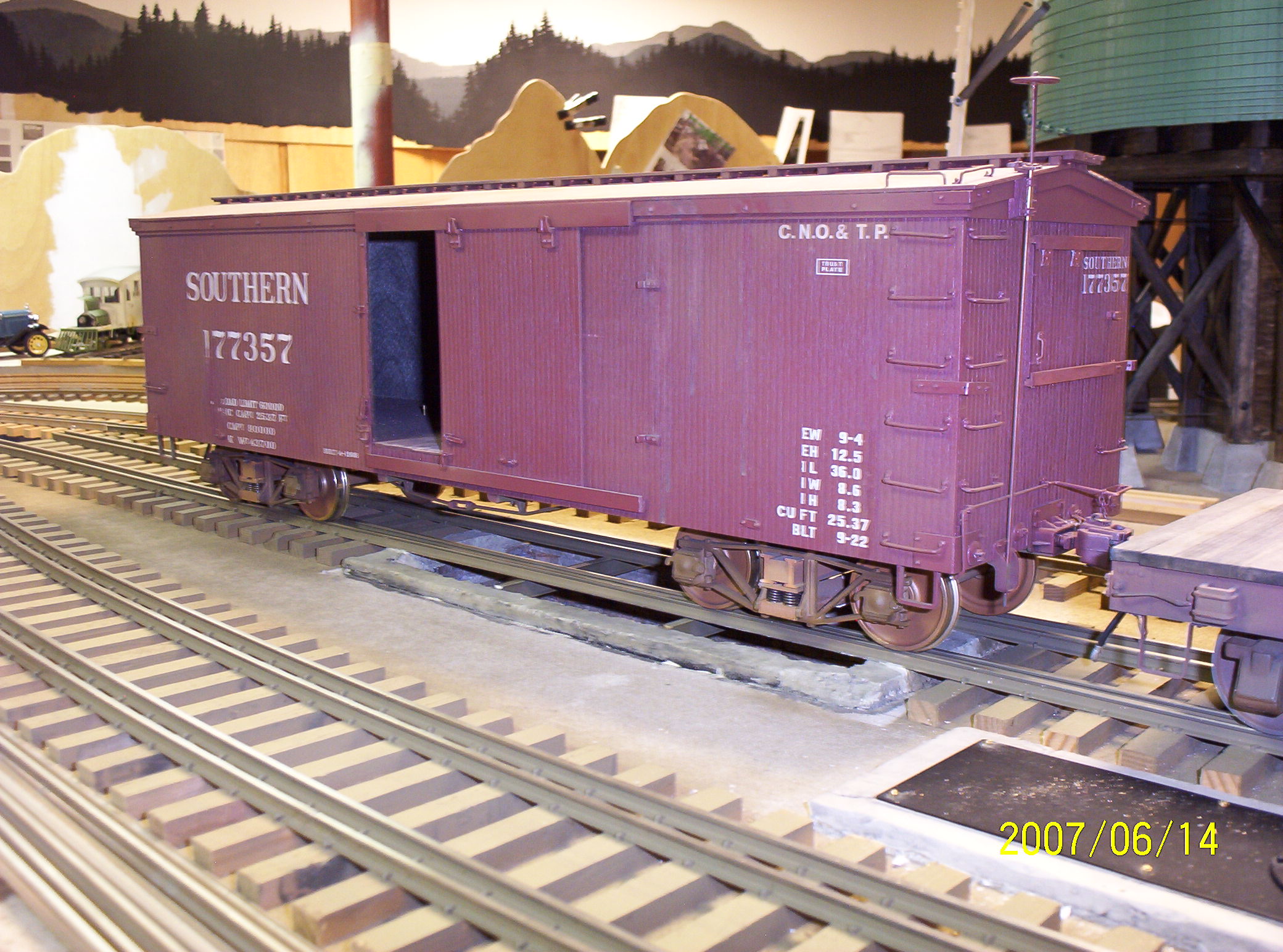
1.JPG)
.JPG)

 |
|
|
The First Cumberland Kit--Maybe
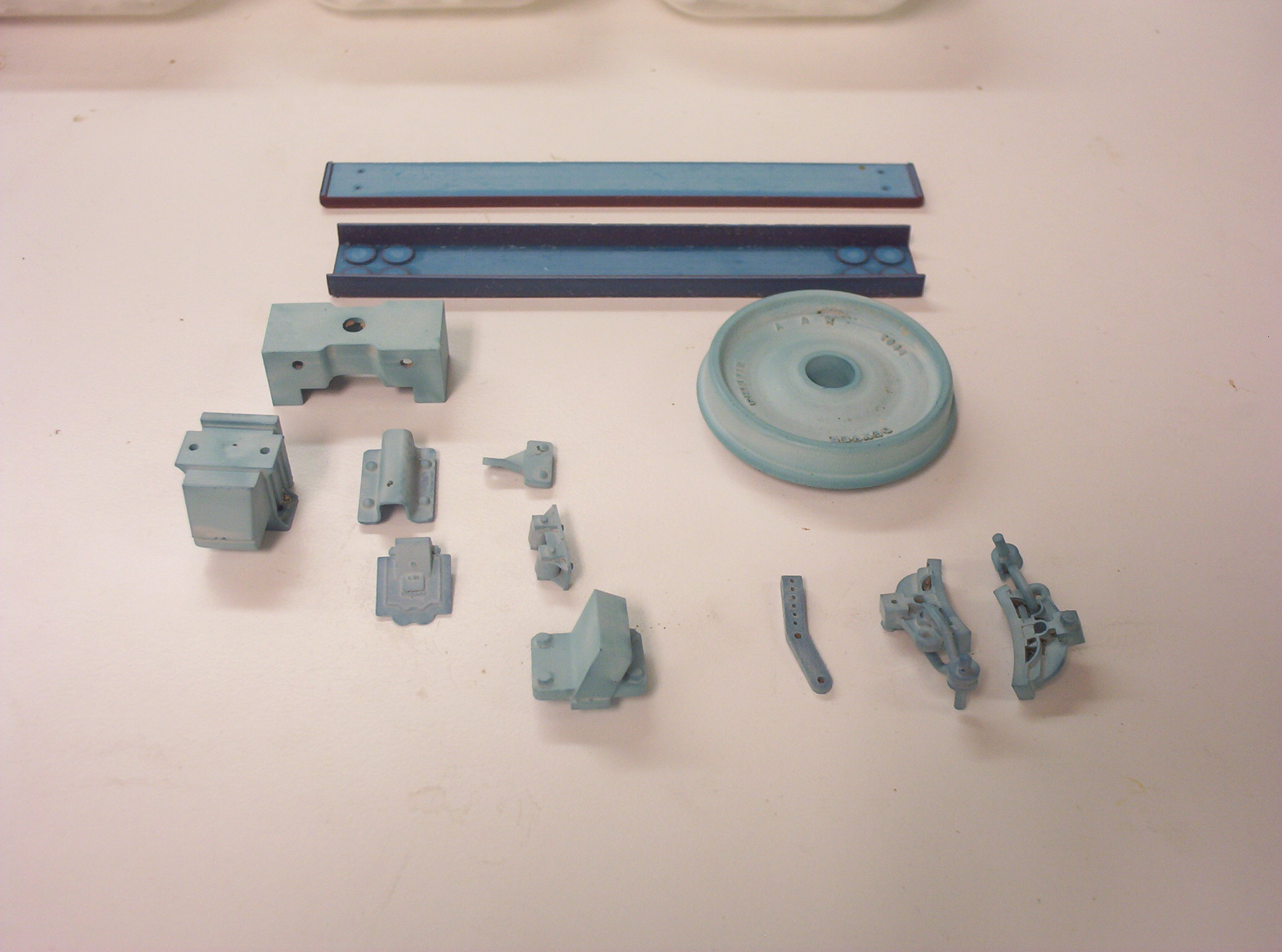
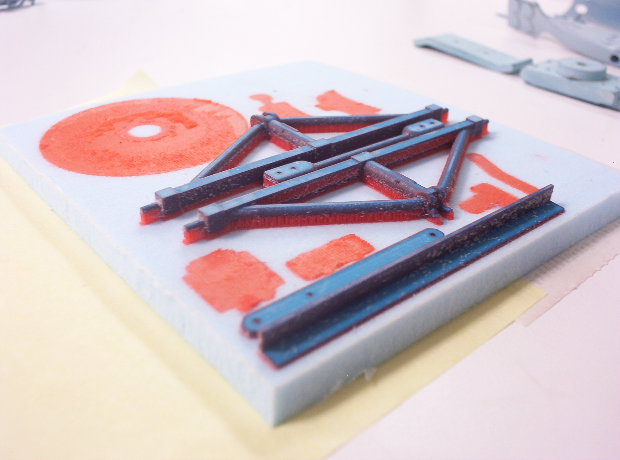
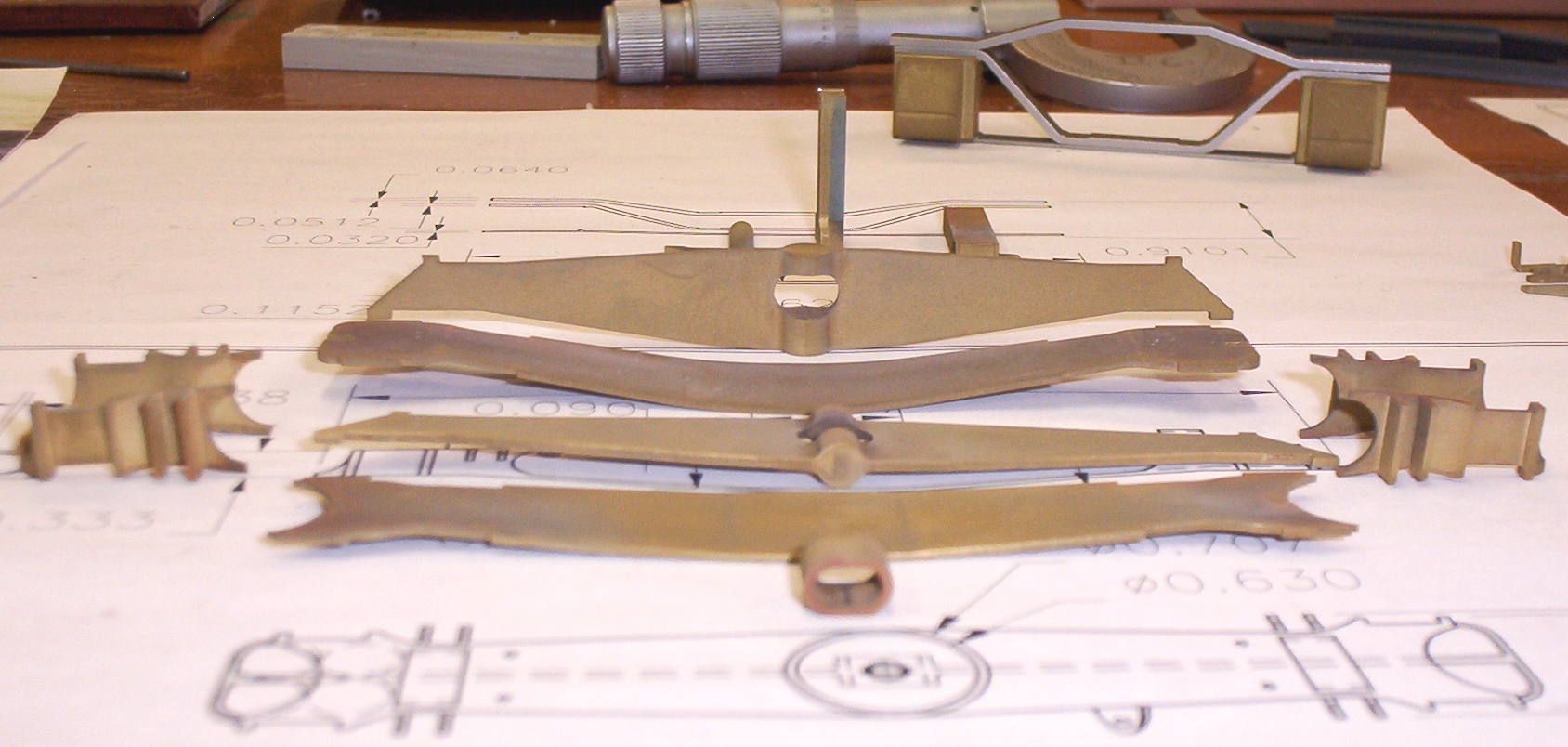
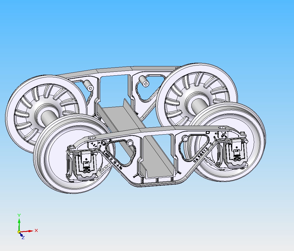
I have now cut most of the bits and pieces which will eventually become casting patterns for the 40 ton capacity, 5'-0" wheelbase archbar trucks that equipped these cars. Here again, almost all my pattern work has been done using a 25 year old Japax wire EDM, based upon my own 2D CAD drawings. Pretty much if I can draw it, I can cut it. The archbars are each individually cut from stainless steel bar stock whereas the columns and journal boxes are cut from brass. Some mill work must be done on the columns and journal boxes; but once complete, the whole assembly will be bolted together with custom-made square headed shoulder bolts, turned on my own lathe. Another major component--the cast steel bolster--was made from six separate components cut--not bent to shape--from brass, and will be soldered together. The spring plank pattern is simply milled and drilled. A metal body bolster pattern remains to be made as of October 2009. All major truck patterns will then be sent either to an investment caster or to a white metal spin caster for copies. Assembling the First Test "Kit"
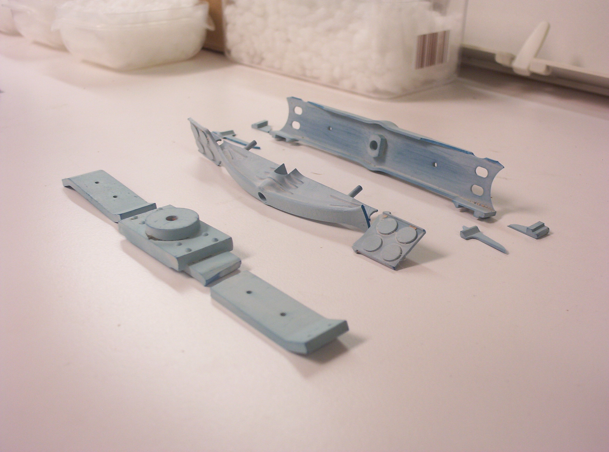
Once the end sills and a few other odds and ends are
cut on my
Micro-Mark miniature table saw,
I'll be ready to assemble the first car body. I will post updates on
this part of the project in the coming months, DV. |
|||
|
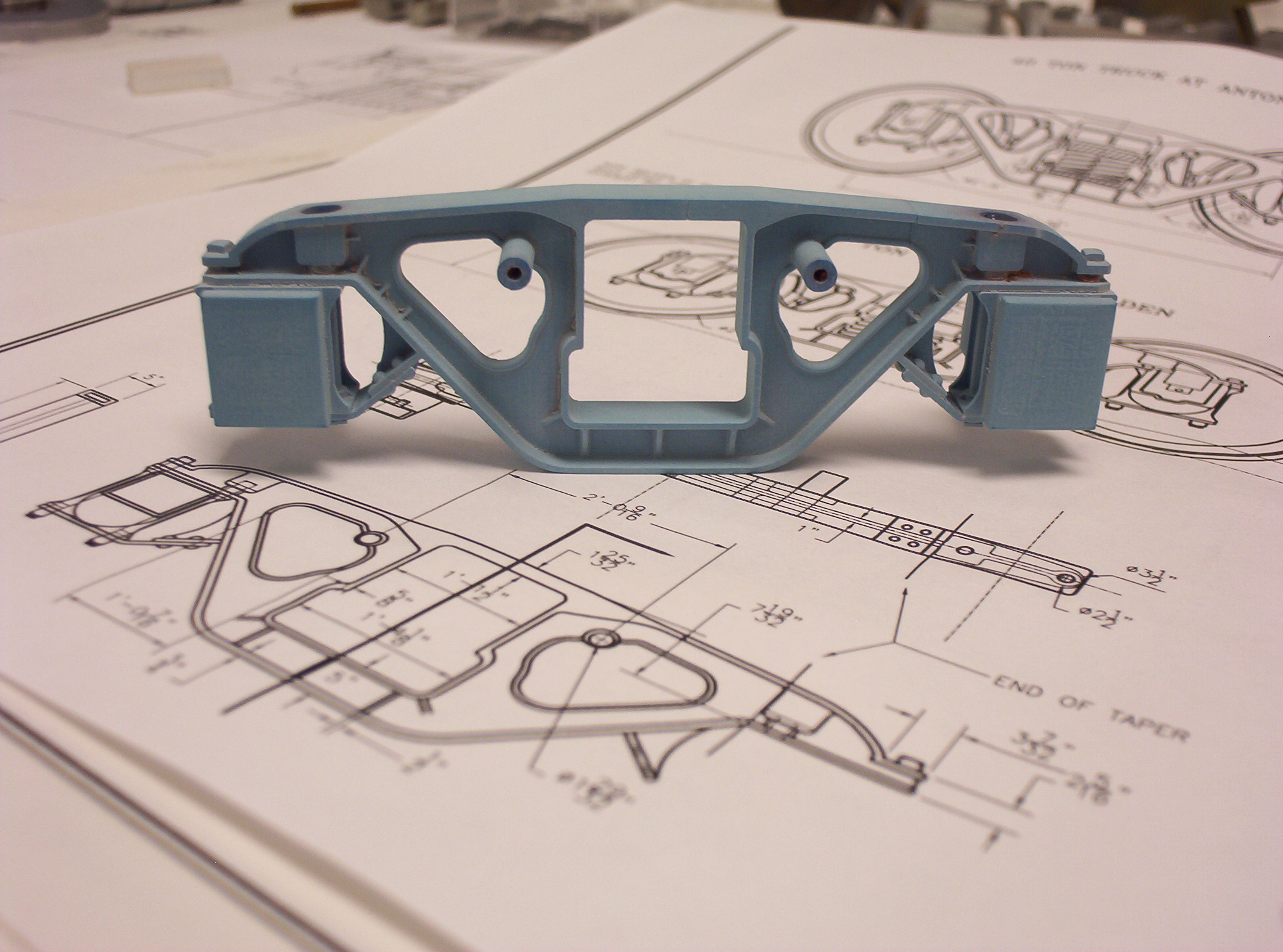
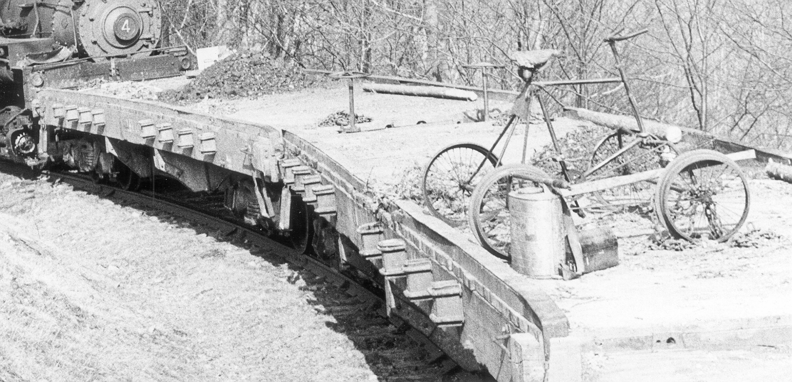
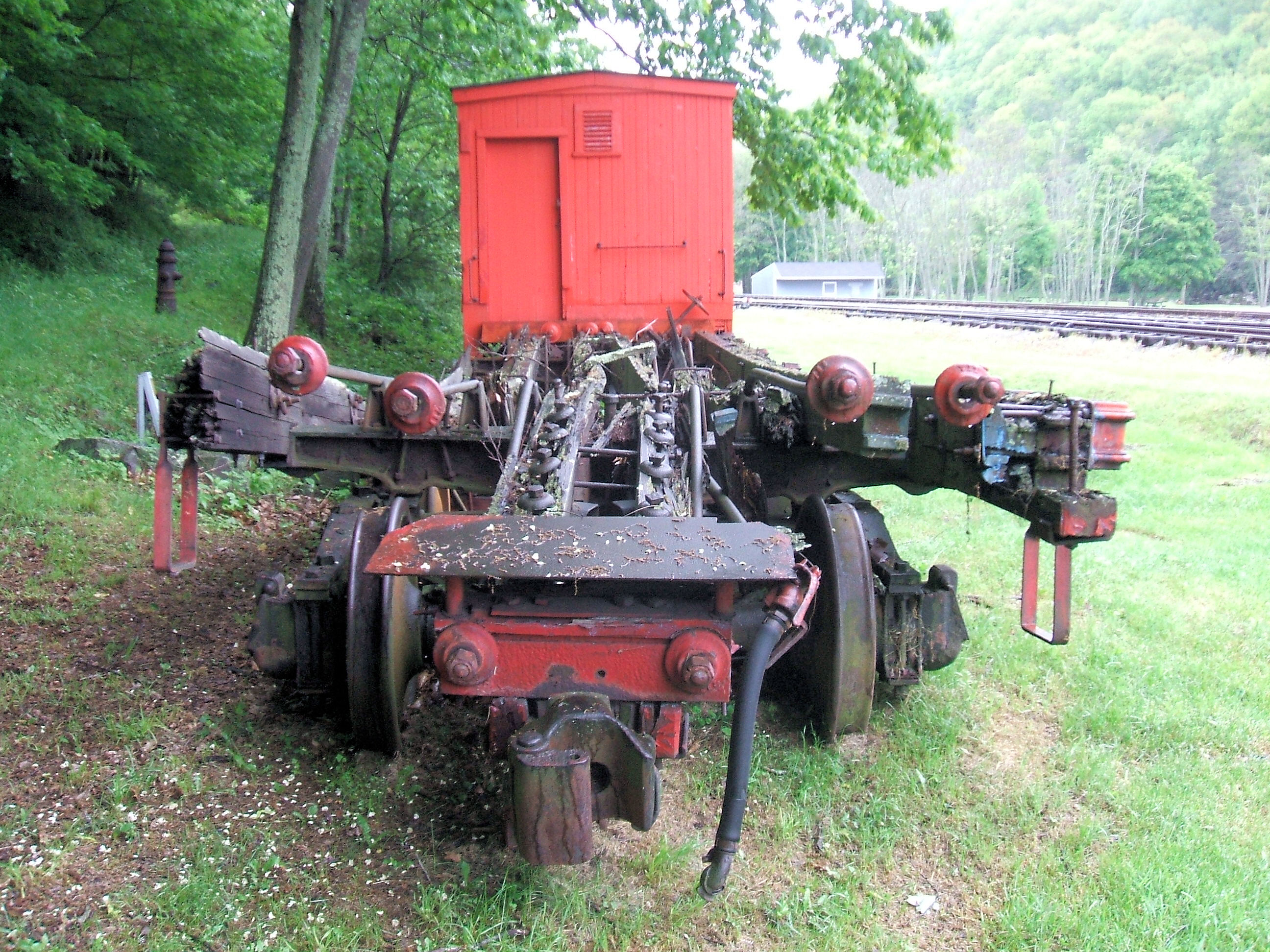
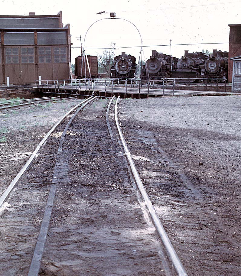
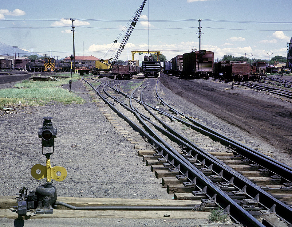
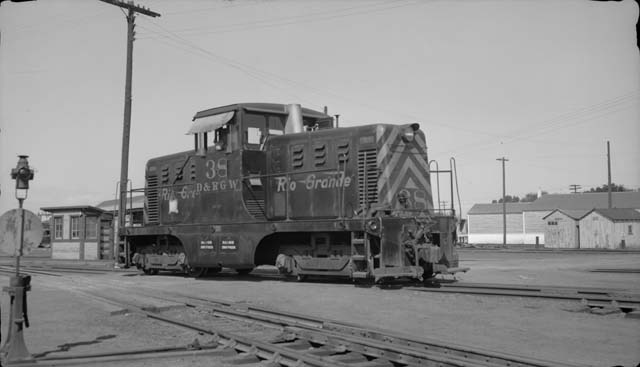
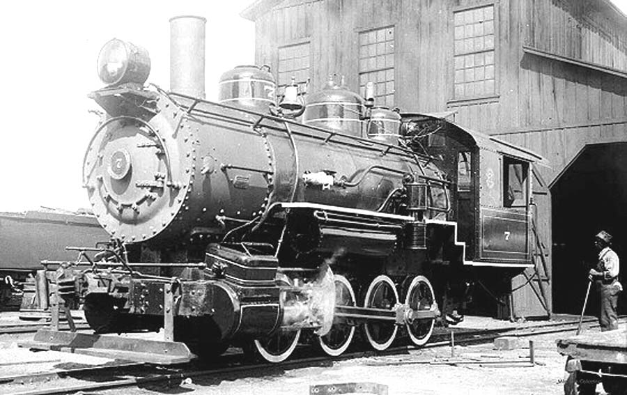
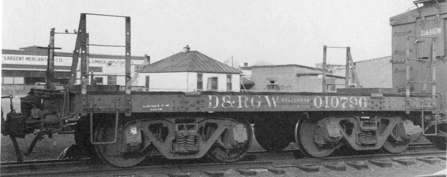
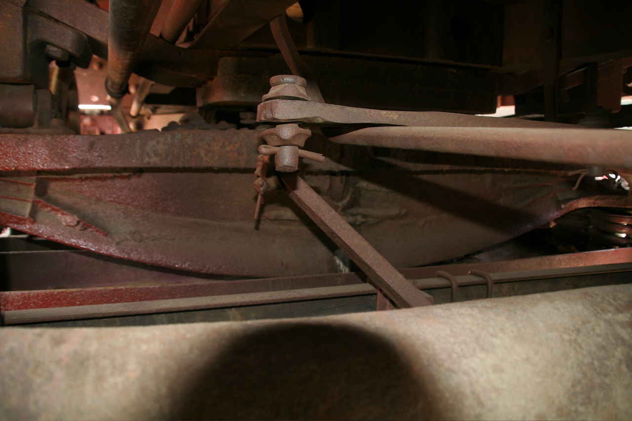
Dual gauge track, where trains of varying gauge share at least one common rail, has never itself been very common in the United States. Only one Class I railroad has operated anything approaching an extensive network, namely the Denver & Rio Grande Western; but short lines such as the East Tennessee & Western North Carolina (or Tweetsie for short) and the East Broad Top have had substantial dual gauge interchanges. Lumber outfits such as the West Side in California also made limited use of dual gauge trackage, mainly around large saw mills. The most common dual gauge trackage has consisted of three rails spaced at 4'-8˝" and 3' intervals, though some special trackwork--such as turntables, ash pits, and their approaches--have used four rather than three rails in order to center up a narrow gauge car or locomotive between the standard gauge rails (see the turntable pics below left). Once there were substantial dual gauge yards at Alamosa, Colorado and Johnson City, Tennessee; but now only the East Broad Tops's surreally overgrown yard at Mt. Union, PA still exists. Dual gauge yards themselves presented unique challenges to both the track gangs who built them as well as the train crews who operated them. For instance, how does one switch a cut of narrow gauge freight cars with a standard gauge locomotive, or vice-versa, if that's all one has on hand?
The full size railroads came up with several working solutions to the problem of dual gauge operations. Here are the most common:
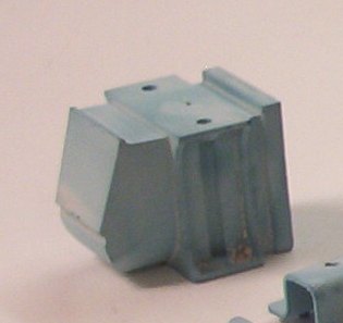
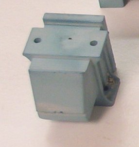
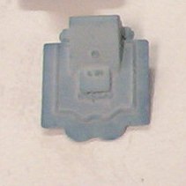
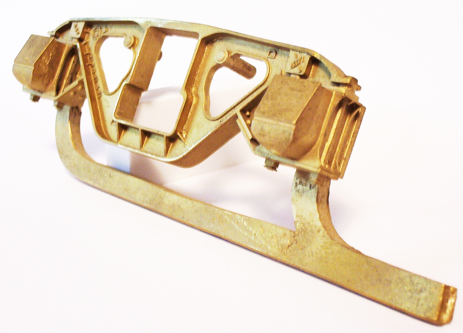
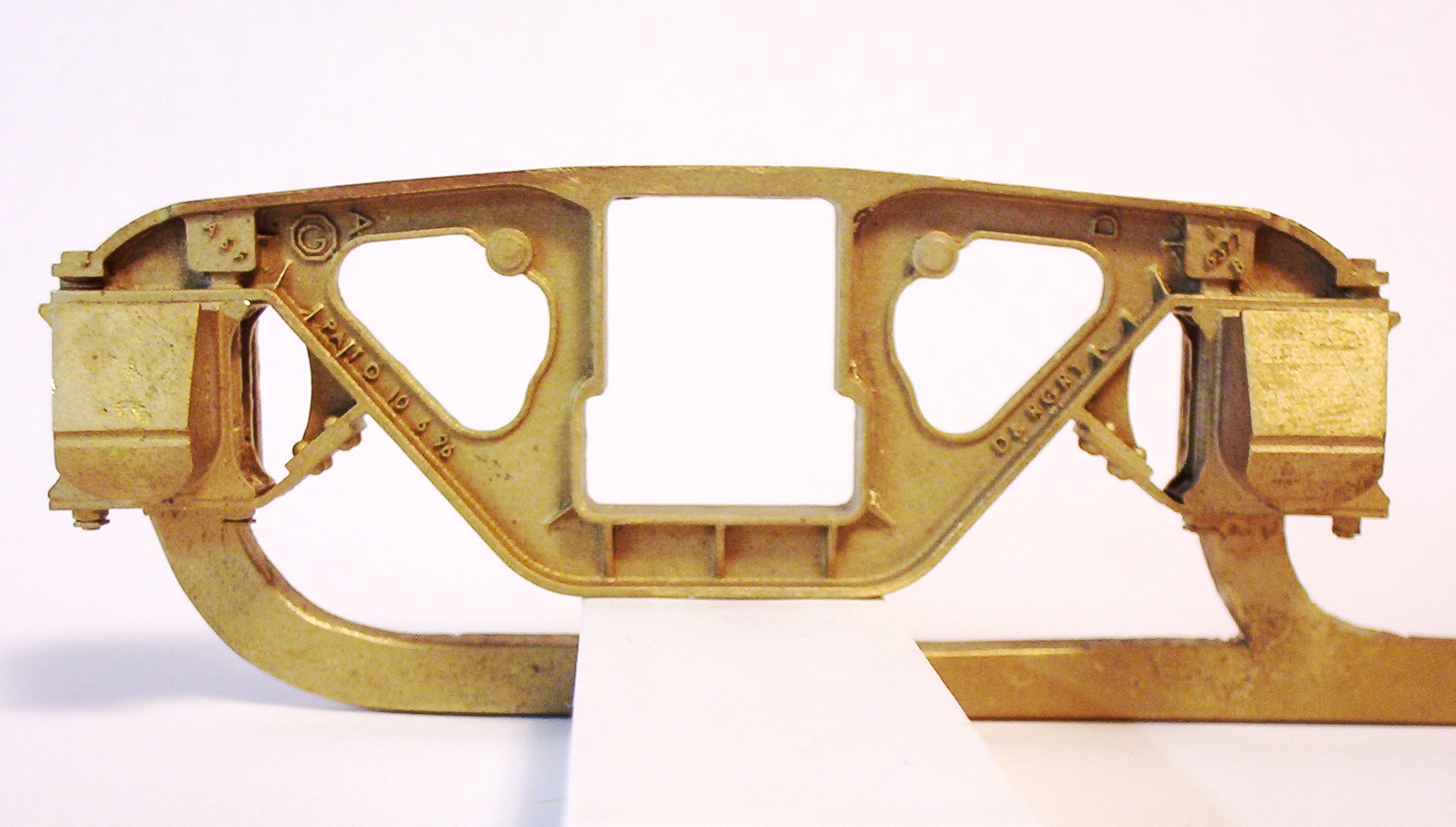
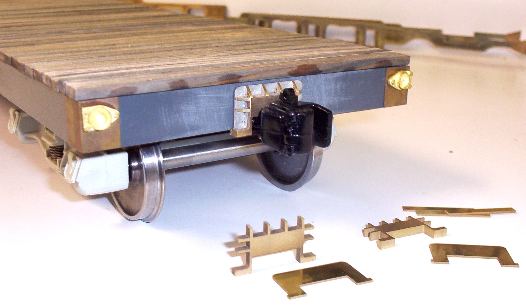
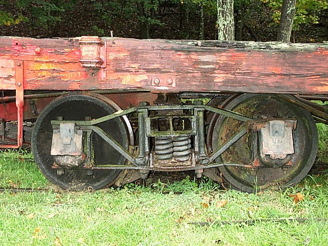
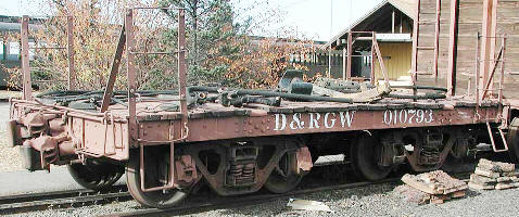
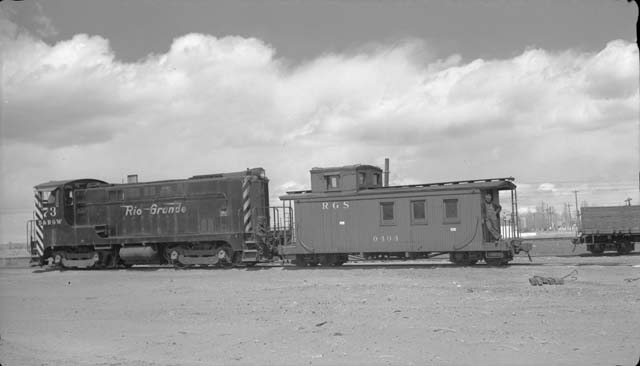
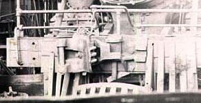
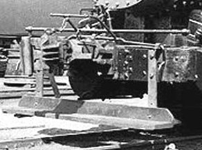
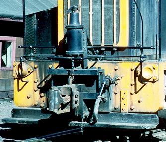
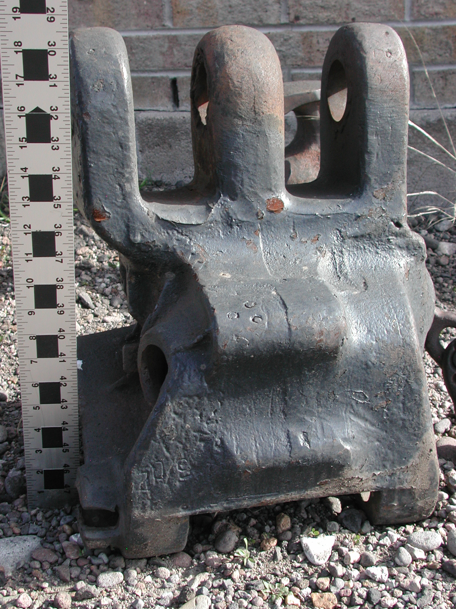
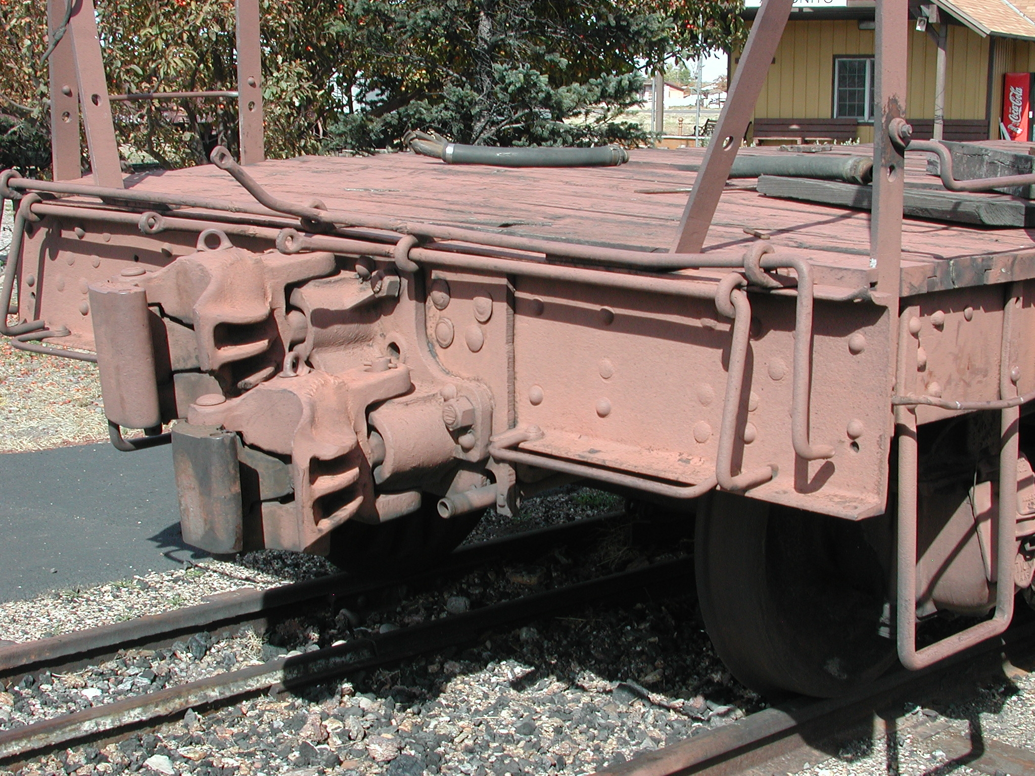
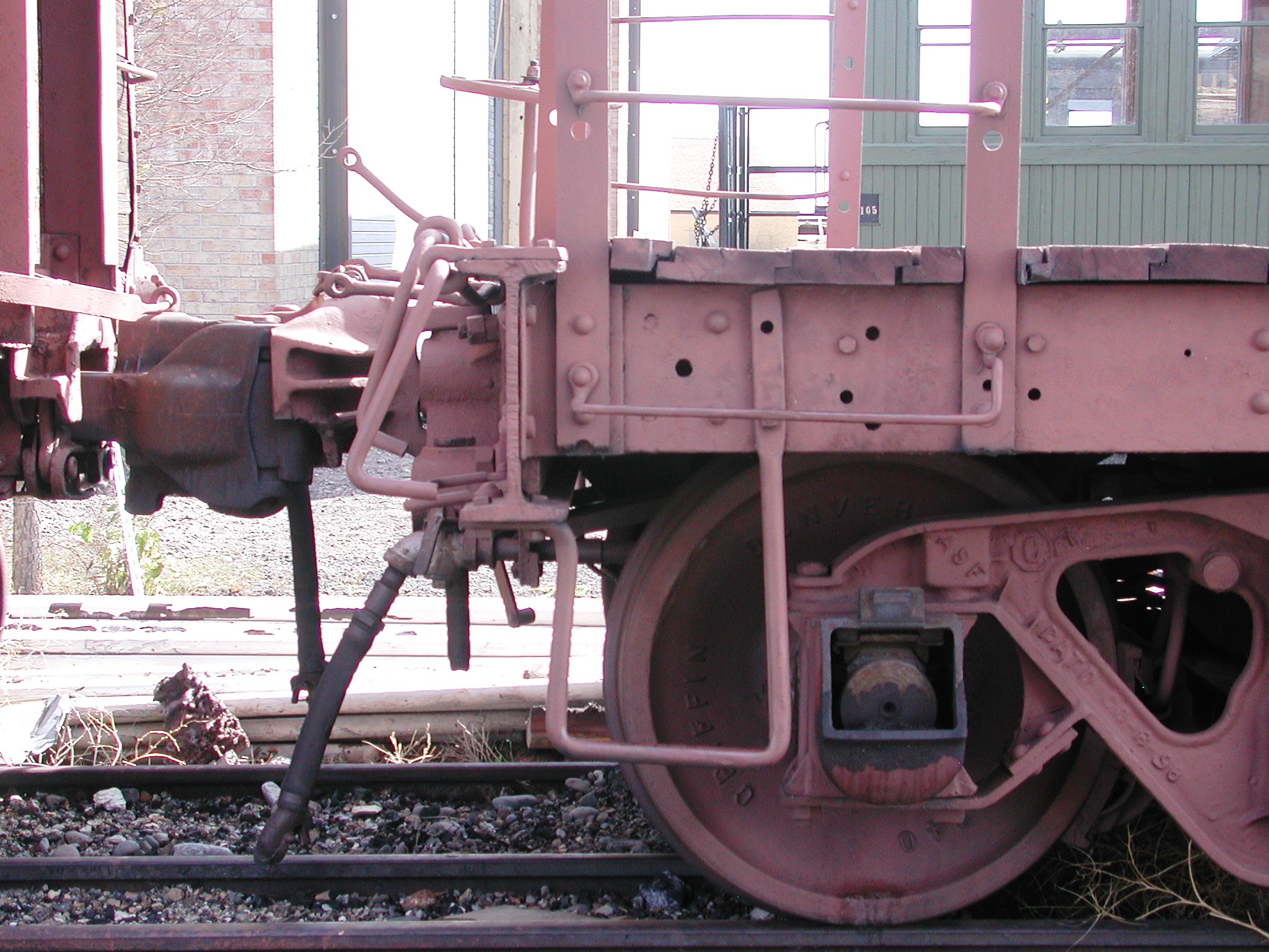
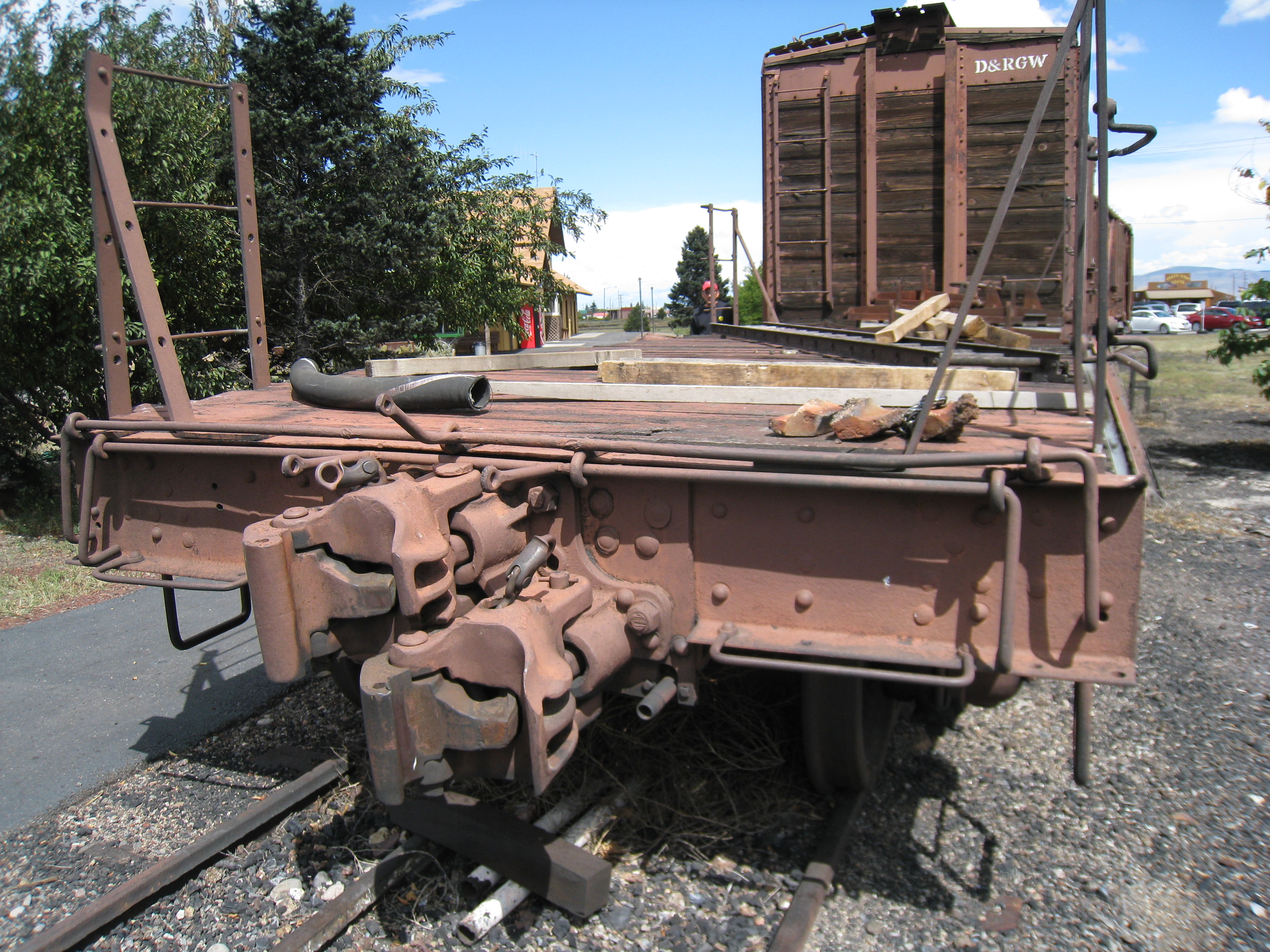
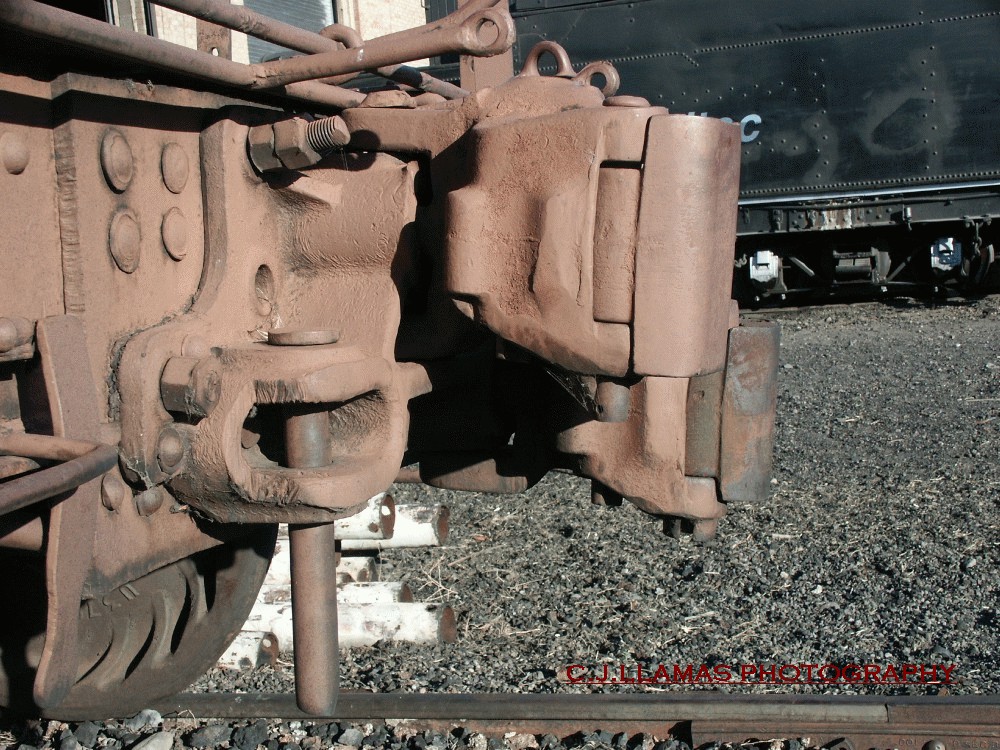
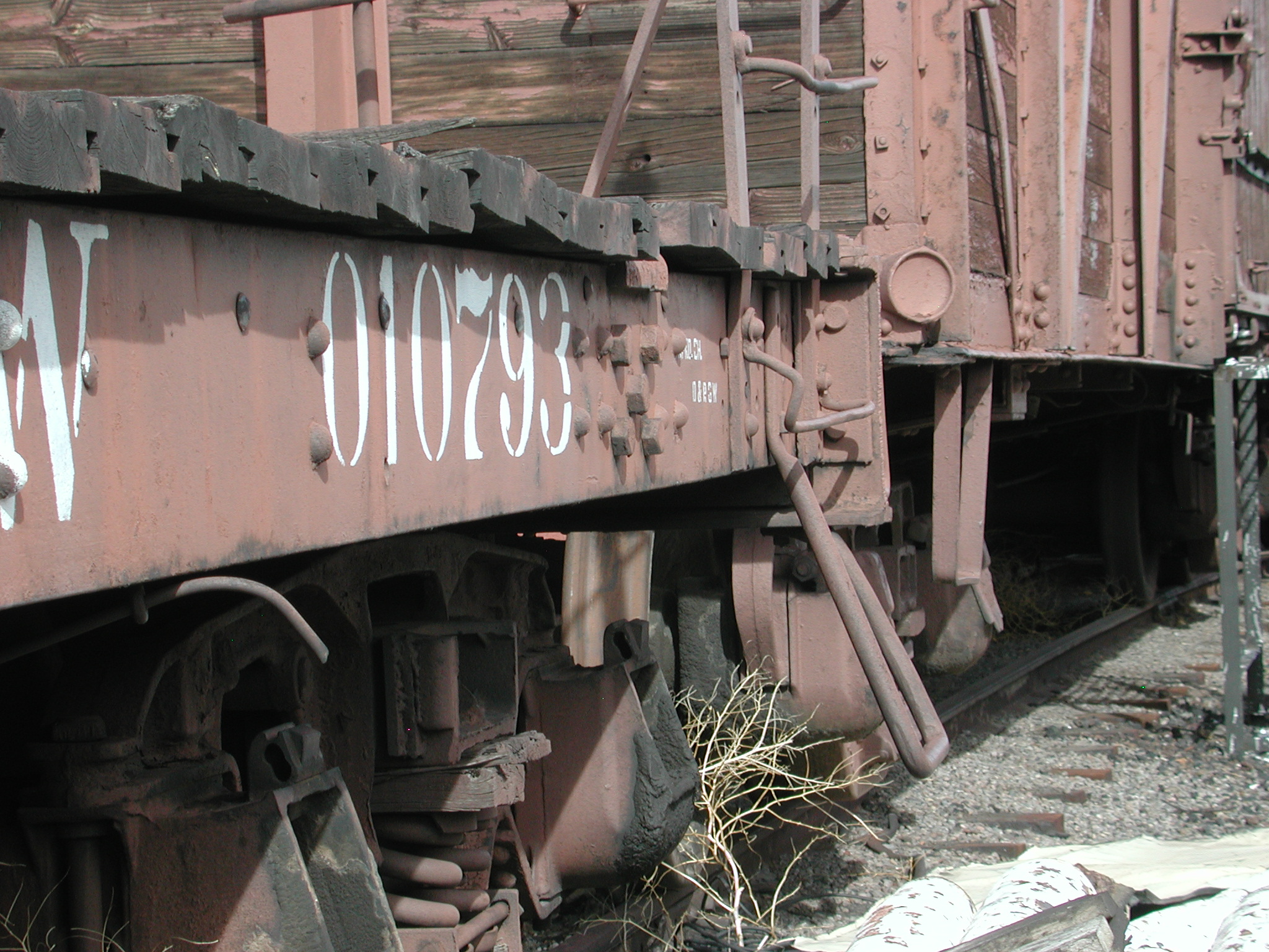
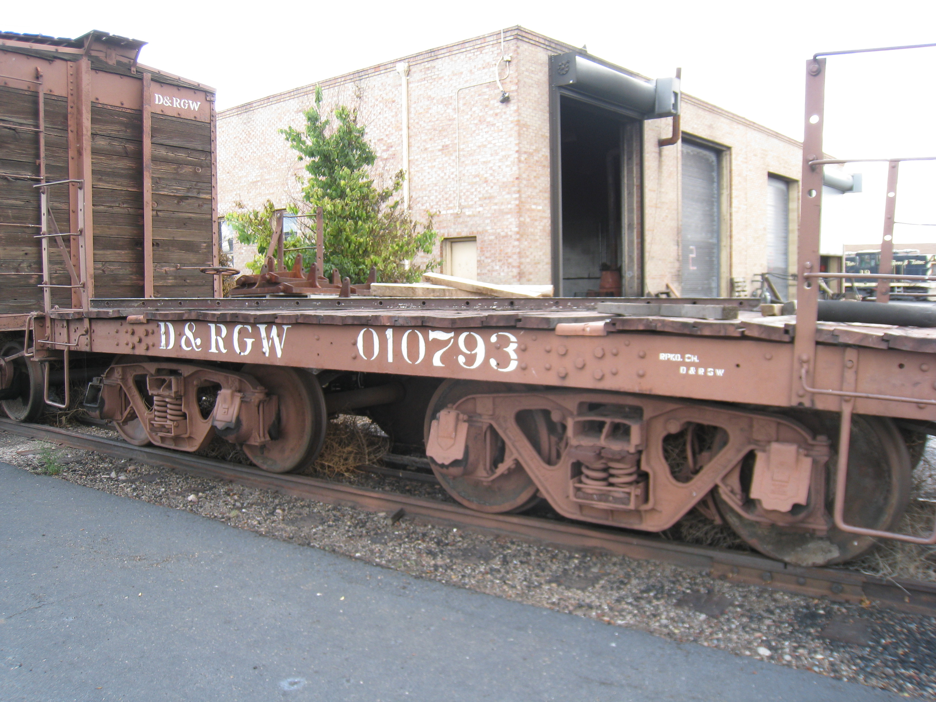
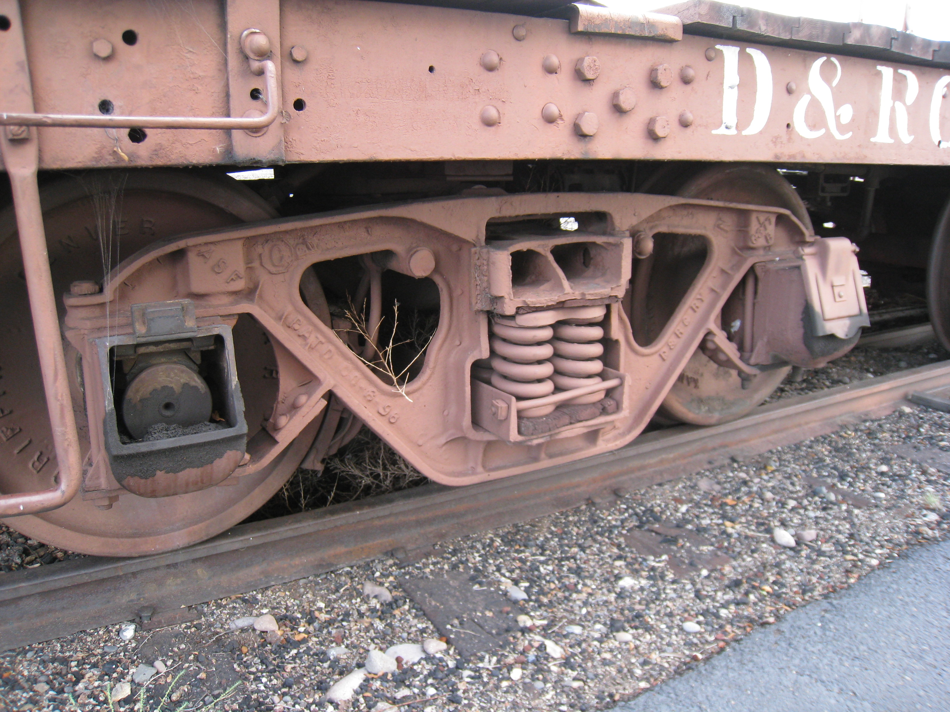
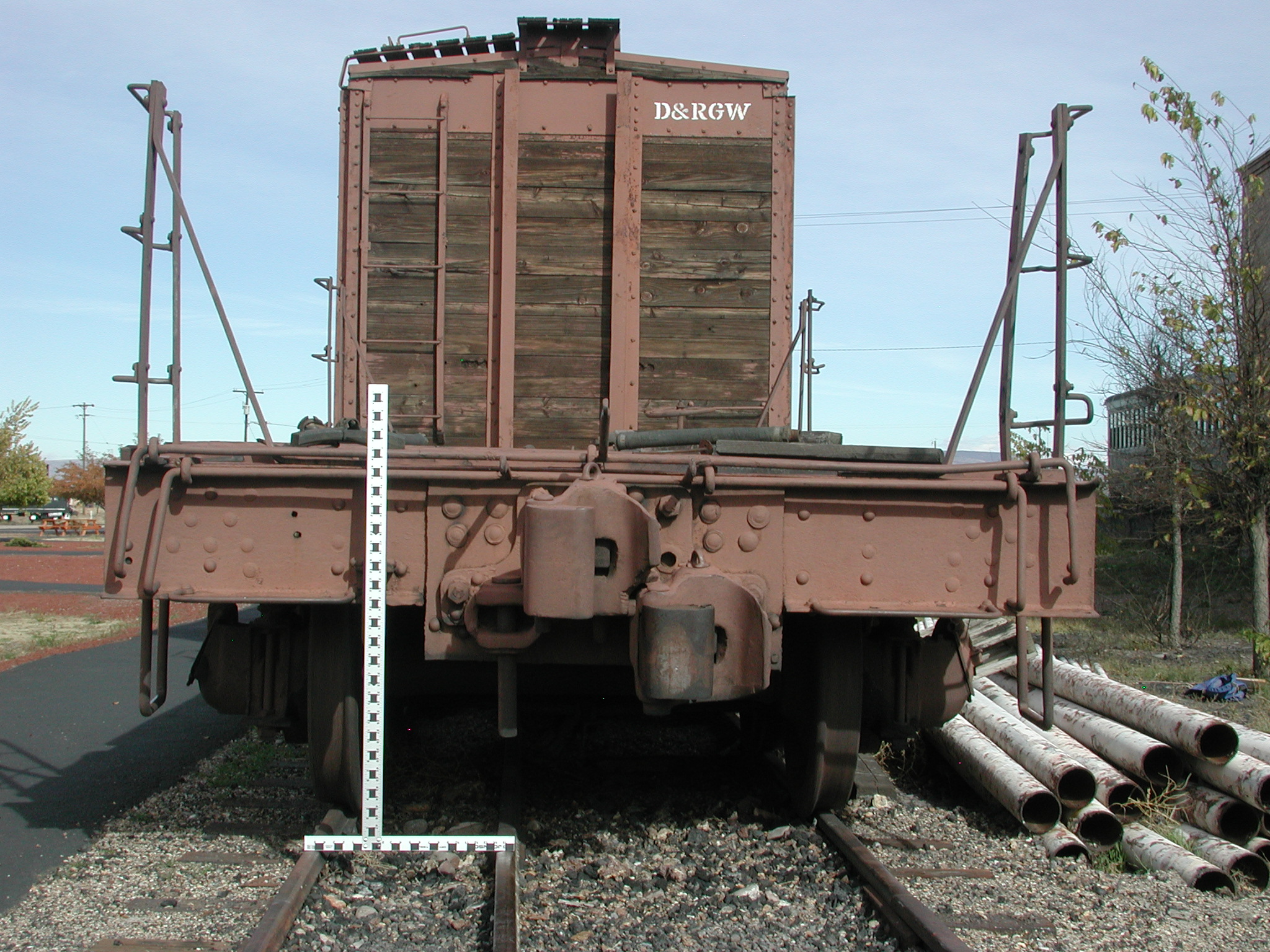
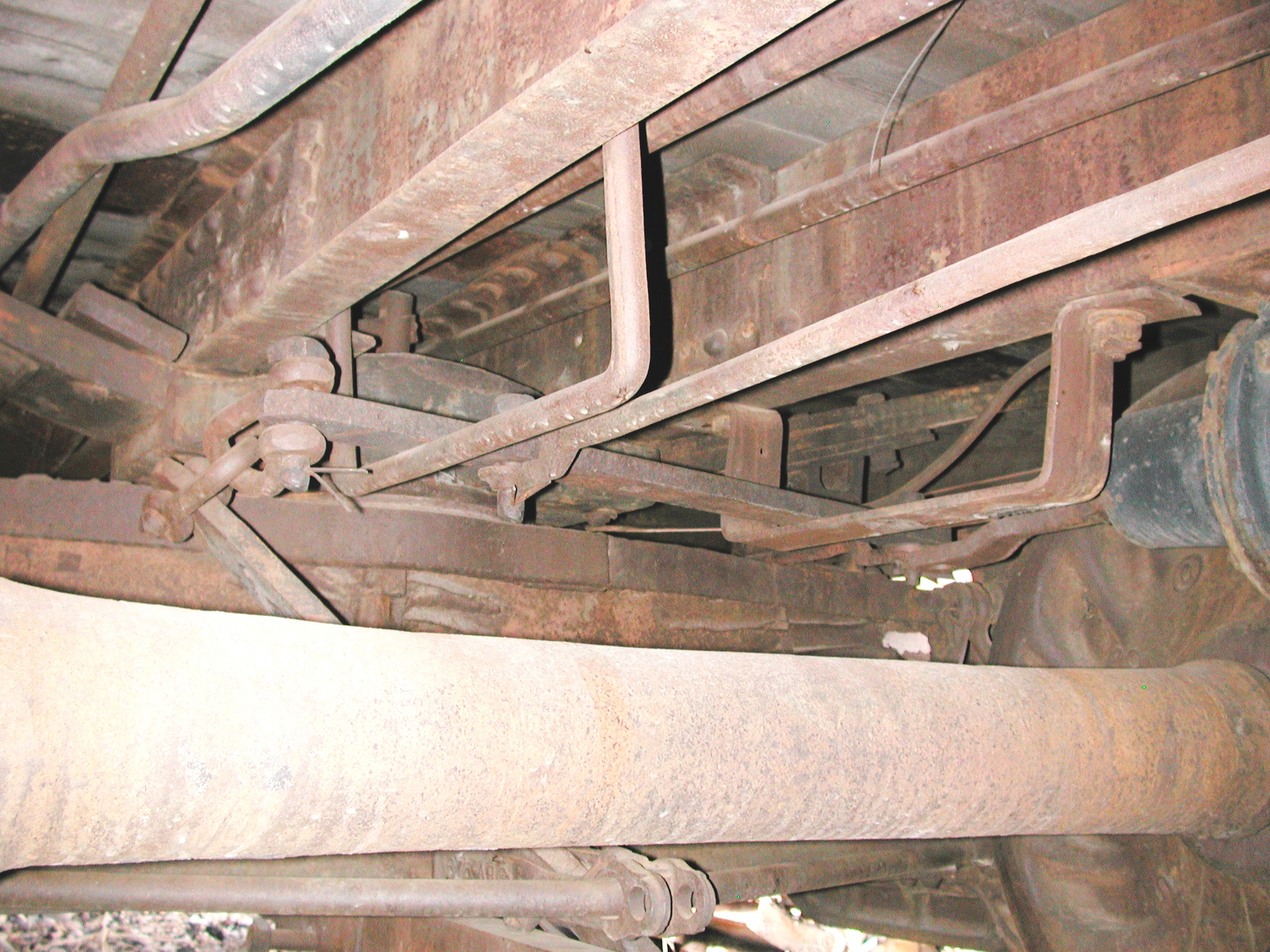
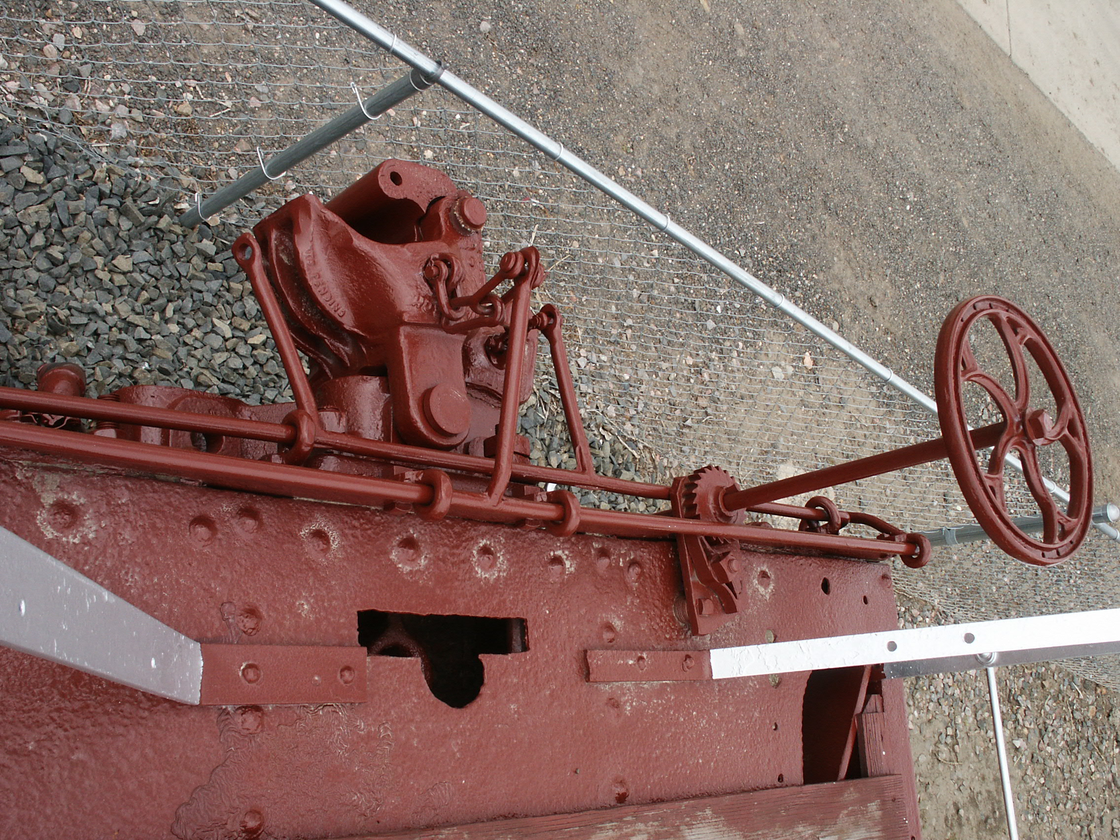
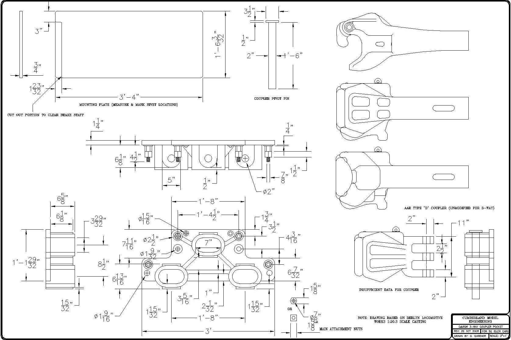
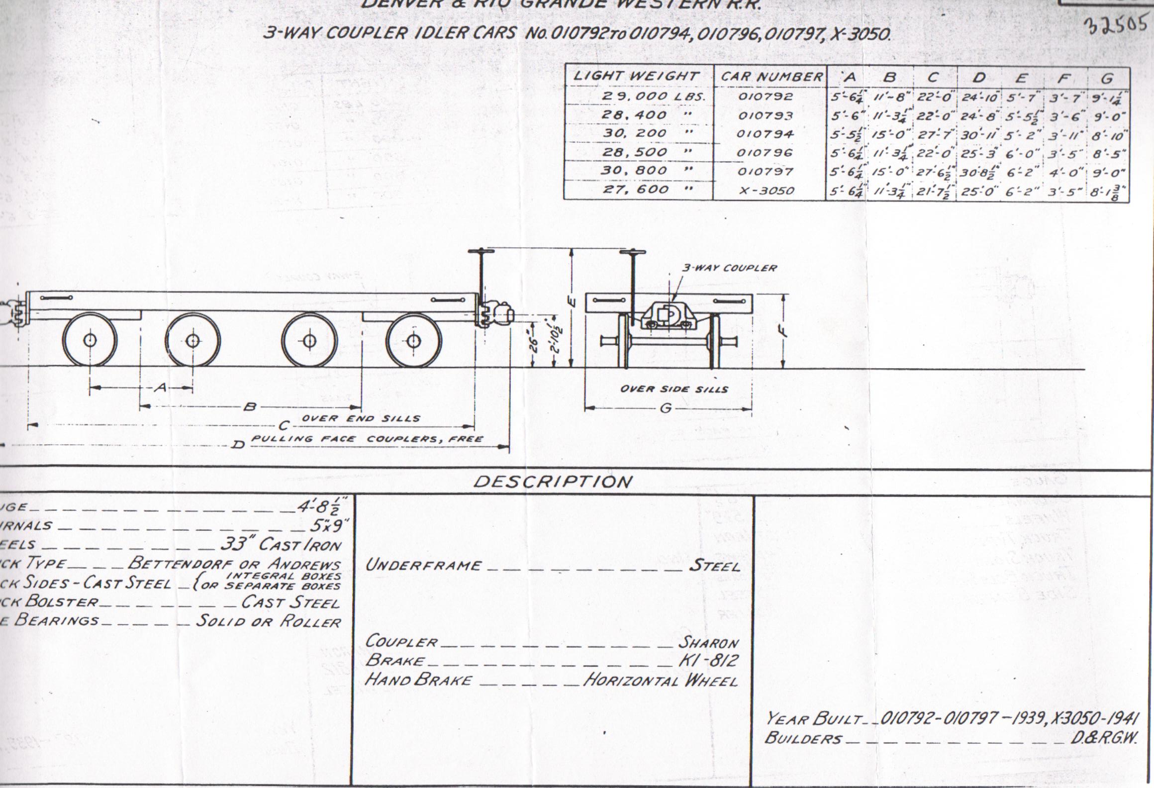
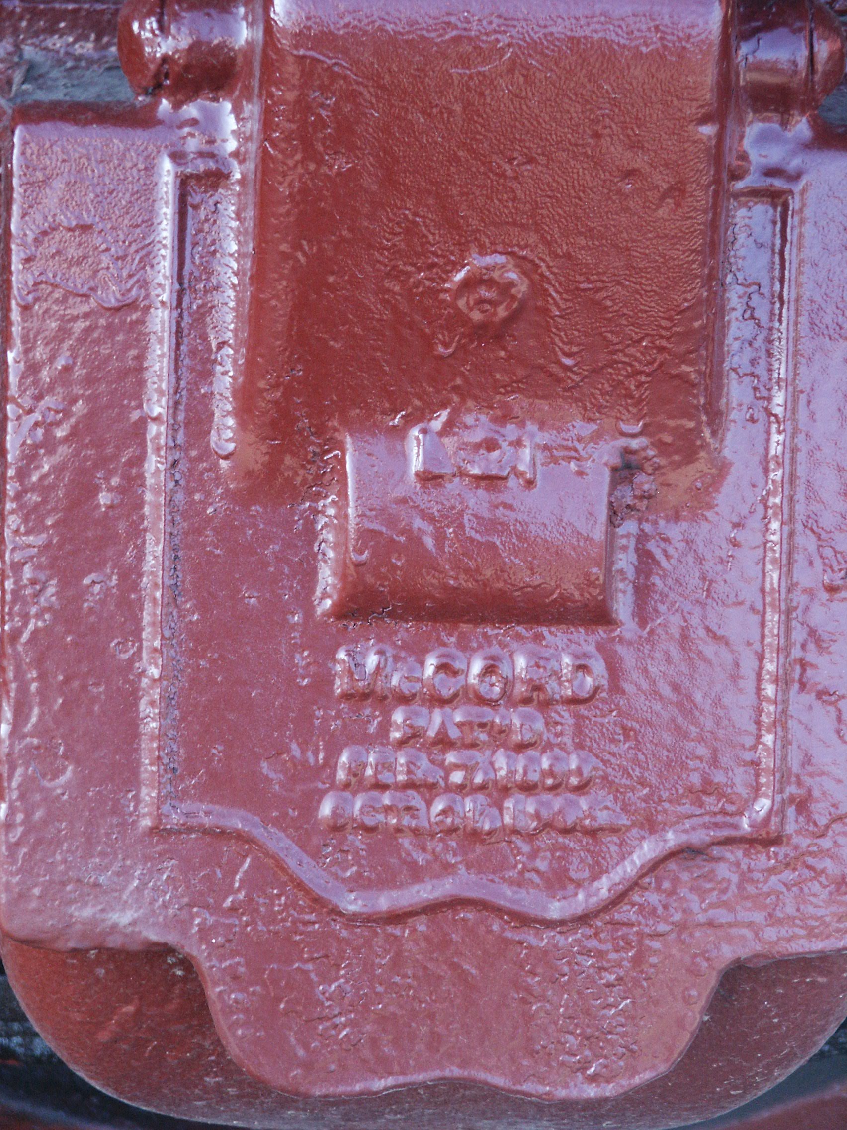
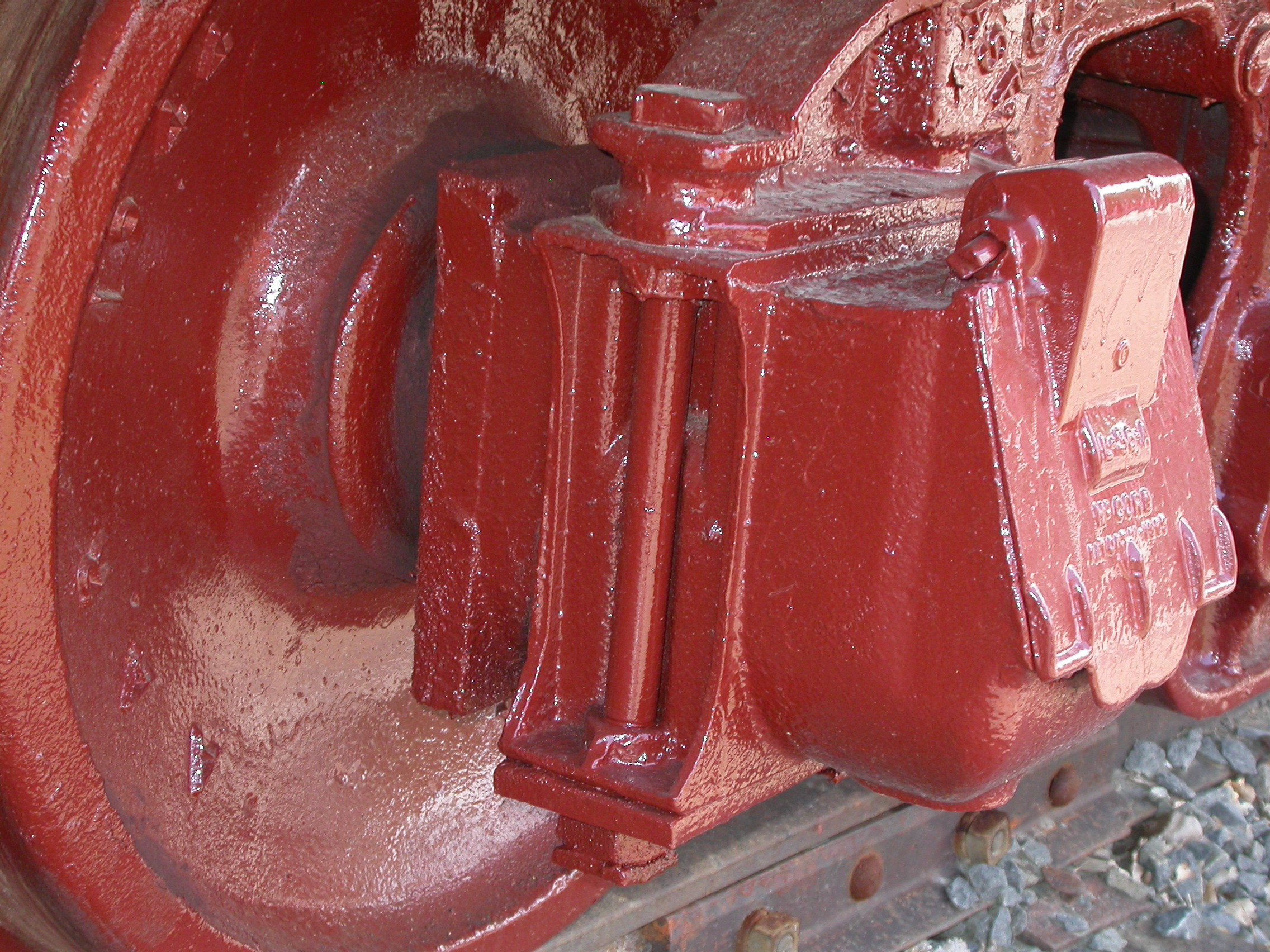
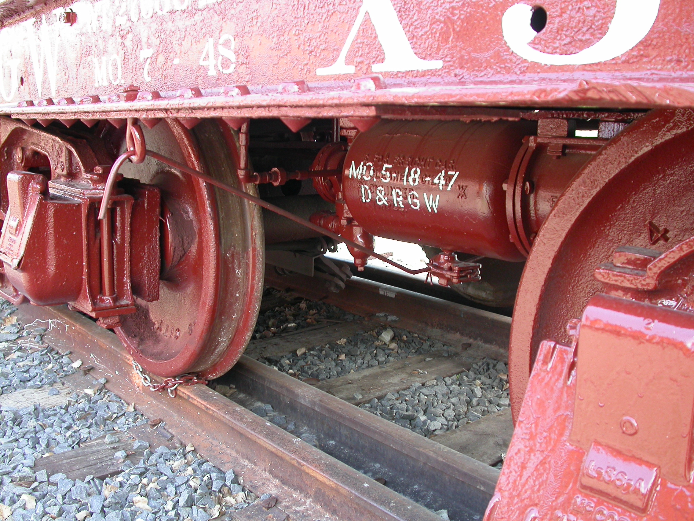
The dual gauge idler cars appear to have been built from the frames of scrapped steam locomotive tenders. No two are exactly alike, though each ride on the same variety of 1898 patent Andrews 40 ton friction bearing truck. The three-position cast steel coupler pocket, which usually holds two removable short shank Sharon brand knuckle couplers, aligns with standard gauge rolling stock in the center position and narrow gauge rolling stock in the lower left and lower right positions. Again, no provision for draft gear was made; and since these cars were not in interchange service (obviously), they remained equipped with K-brakes until the end of dual gauge operations. In use these peculiar cars carried no freight, and should be distinguished from the more familiar variety of narrow gauge "idler" flat used by the D&RGW during the 1950s Colorado gas well boom, the latter cars acting as "spacers" between narrow gauge gondolas which actually bore the weight of oversize lengths of pipe. Two cars have survived, one at the Cumbres & Toltec Scenic Railroad at their Antonito terminus--right next to the two remaining D&RGW 40' Fowler clone boxcars (which were last in use at Alamosa as "stores cars," hence their unlikely survival)--and the other at the Colorado Railroad Museum outside of Denver at Golden. Apparently the Colorado Railroad Museum still gets some use from its idler car, at least from time to time (note turntable pic above). |
|||
|
Idler Car
#010793 at the
Cumbres & Toltec Scenic Railroad in
Antonito, CO.
|
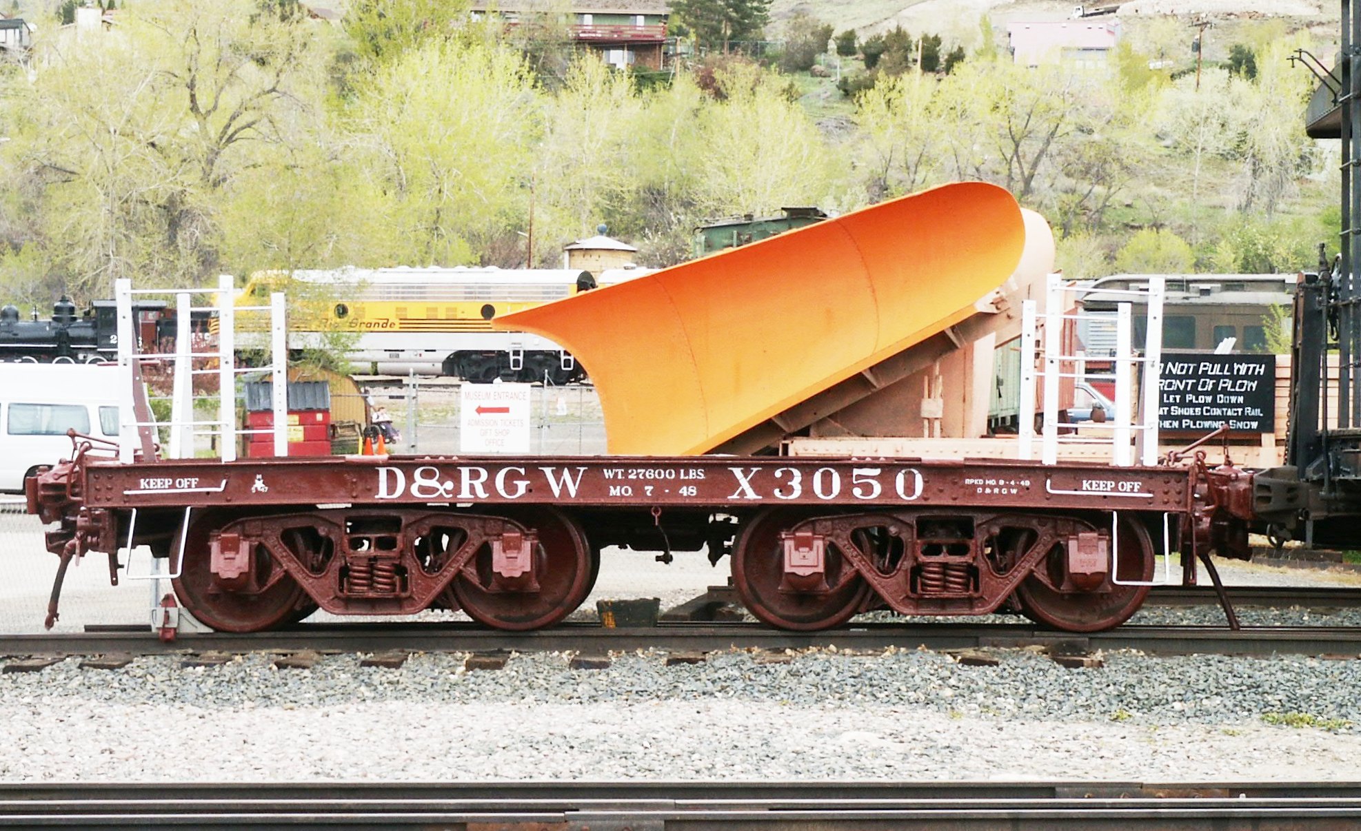
Idler Car
X-3050 at the
Colorado Railroad Museum in Golden, CO. (Photos by Kevin Strong)
|
||
|
Modeling a Rolling Stock Oddity My friend Barry Bogs first introduced me to the D&RGW idler cars on his Gauge 3 layout: "What's that," I asked. "Oh, that's an idler car, David." "You made that up, didn't you? Pretty neat, just the same," says I. "No, they really did exist. The D&RGW had several of them. There's one up at Antonito. They used to run them on dual gauge trains." So with my initial incredulity satisfied by a handful of prototype pictures, I was convinced this was not the work of Mr. Bogs fertile imagination, but rather what could be a very useful, prototypically faithful, car to have around for dual gauge operations. But how to build one, maybe several?
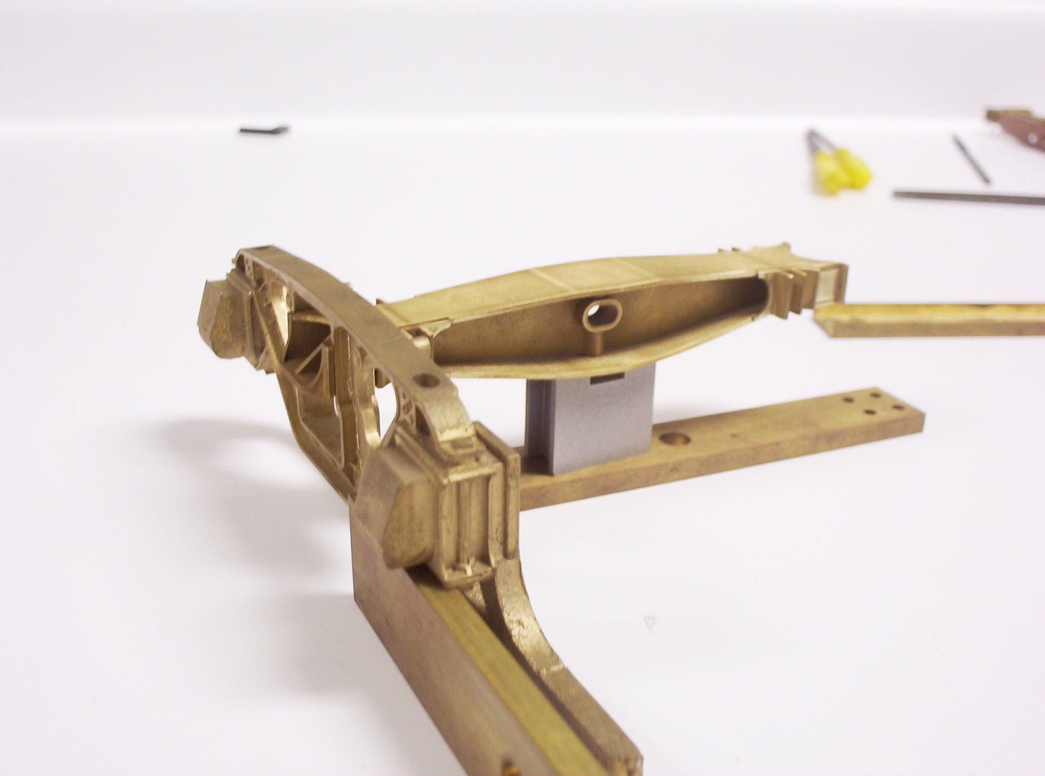
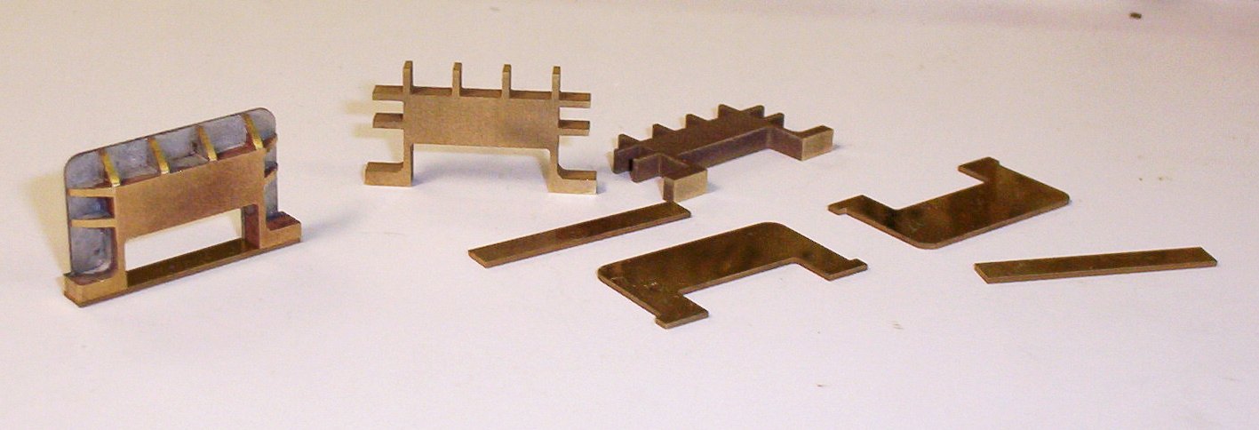
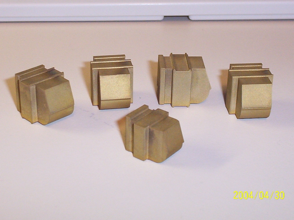
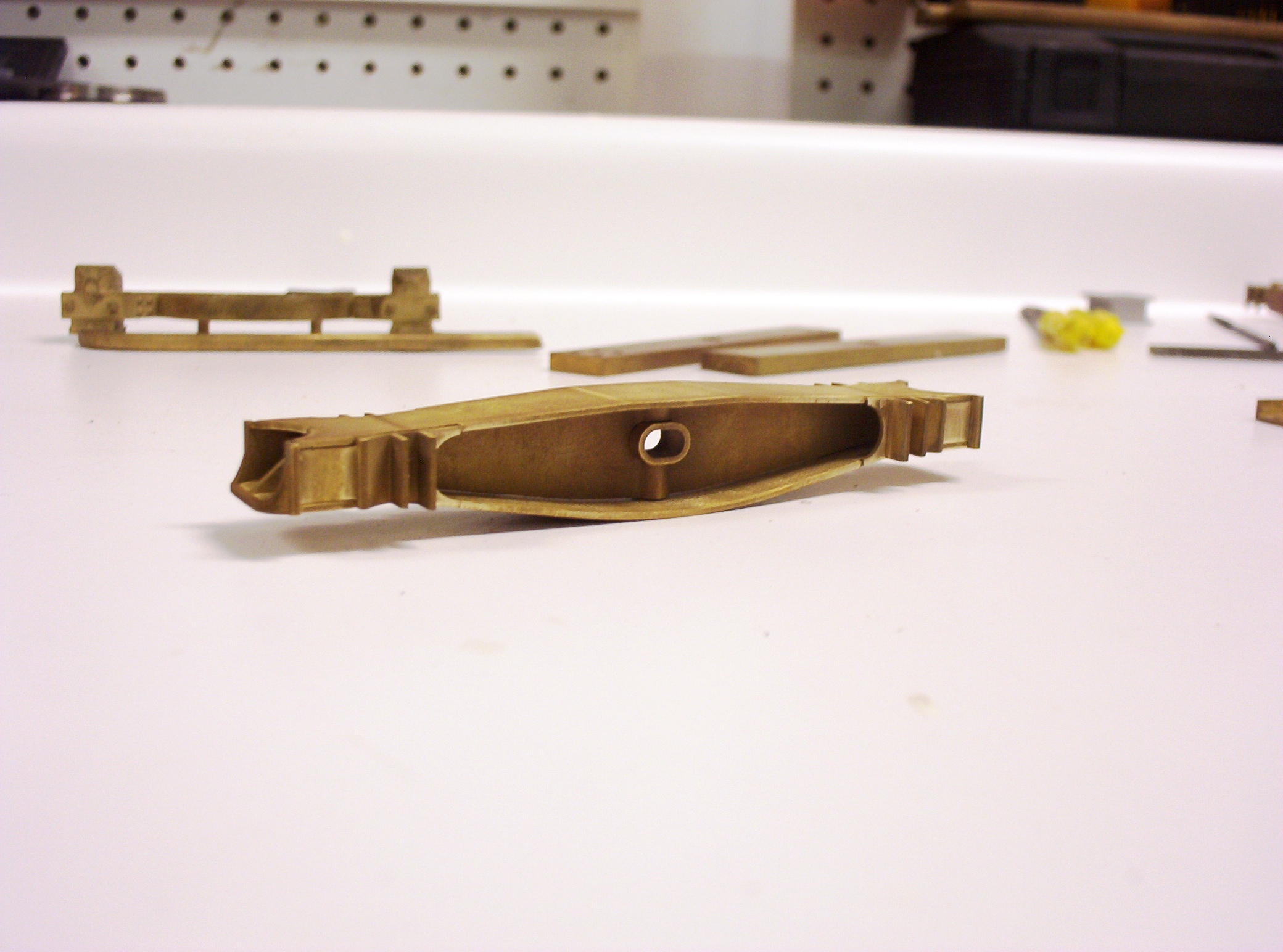
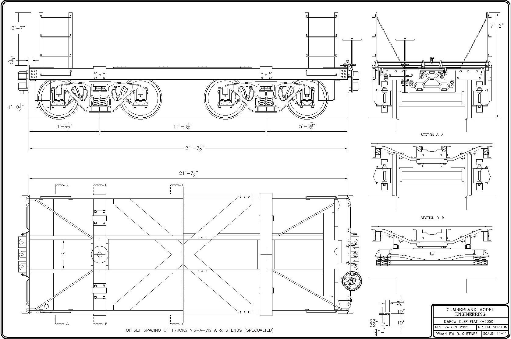
The first tangible evidence of a real project has been the production of rapid prototype based investment cast brass truck patterns. To the best of my knowledge, though there have been O and HO scale models of these cars, no one else hitherto has made exact scale patterns of these early Andrews style trucks with the strap locations and raised lettering which make them distinctive to the D&RGW. It's been something of a labor of love, since part of the goal has been not simply to get the sideframes right, but also the truck bolster, body bolster & brake rigging too!
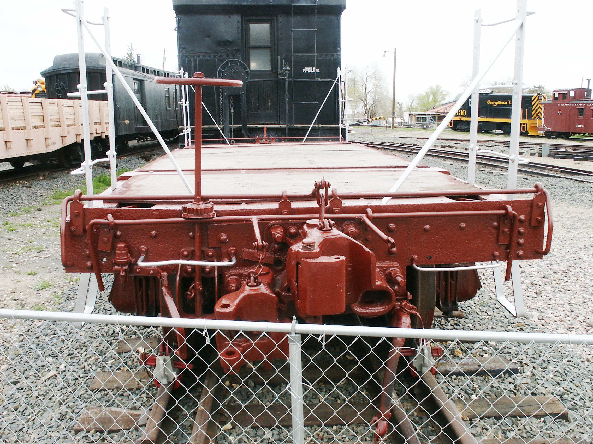
The First Semi-Kit In August of 2005, I began work on an initial one-off model of the X-3050 for my English friend John Masters. Basically, I provided John with two brass body bolsters, end sills, and coupler pocket mounting plates, all of which were cut on my Japax wire EDM, along with Special Shapes ˝" tall brass channel to duplicate the prototype's 10" center and side sill channels. Theo Berlyn (of Berlyn Locomotive Works) had at this time manufactured a number of extra investment cast 3-way coupler pockets from his Fn3 K-37 project, several of which I included in the semi-kit. Six Accucraft couplers, Hartford air hoses and glad hands, some brass bar stock for forming handrails, my scale drawings, and stained western cedar decking completed this rather Spartan kit. Speaking of the latter, it is my guess that the X-3050 originally had tongue-in-groove boards for its decking rather than its current plywood, hence the western cedar decking. Anyway, there were no trucks available at that time (soon to be rectified), and so the semi-kit looked like this: More To Come . . . (last update: 10-16-09) |
|||
|
Last update: 16 October 2009
|
|||
|
Copyright 2004-2009 CumberlandModelEngineering.com. All Rights Reserved |
.JPG)
%207-29-09.JPG)
.JPG)
.JPG)
%201.JPG)
%202.JPG)
.jpg) American
Car & Foundry 40' Fishbelly Center Sill Flat Cars
(2001, 2005-09)
American
Car & Foundry 40' Fishbelly Center Sill Flat Cars
(2001, 2005-09)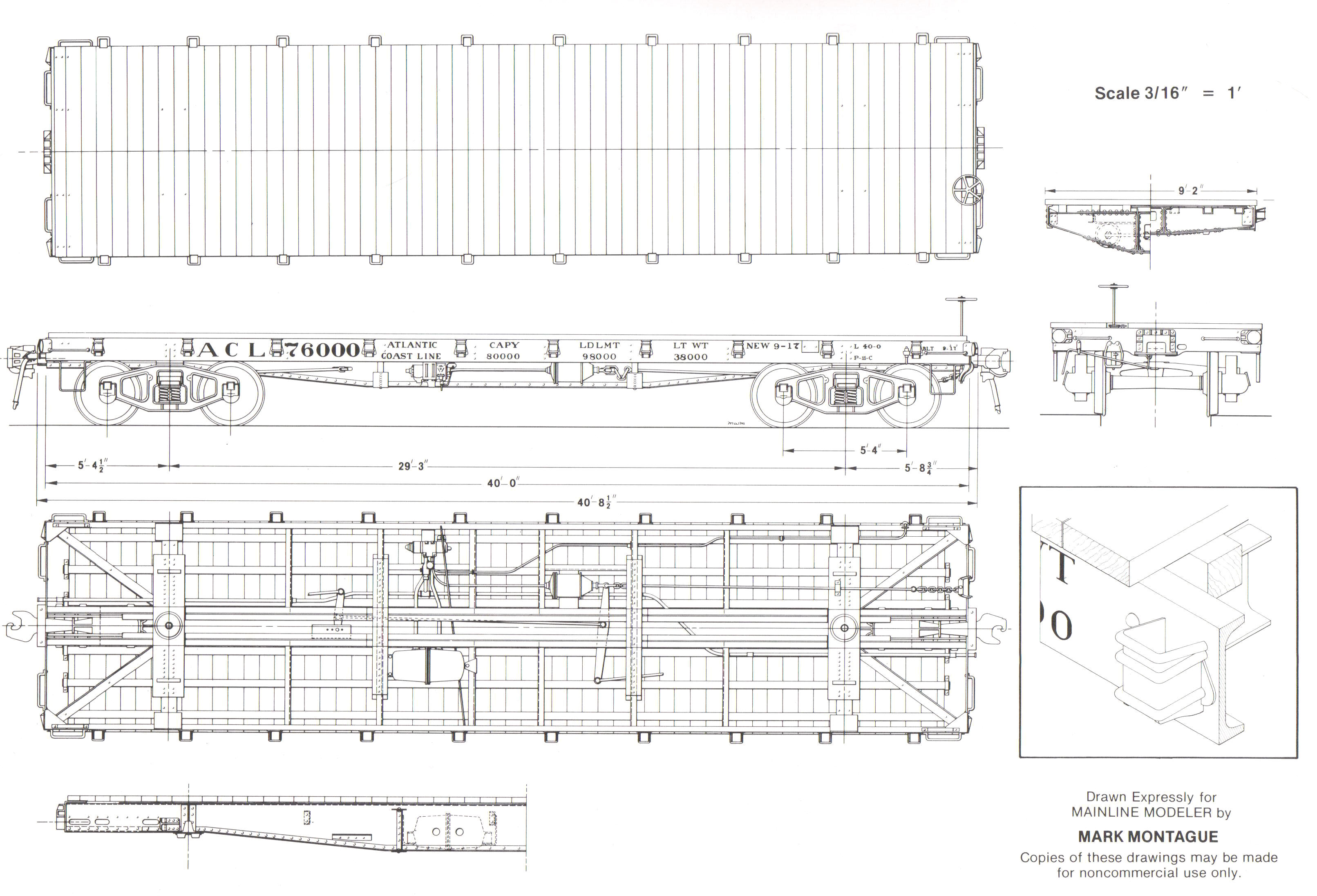

.gif)
.JPG)
.JPG)
.JPG)
.JPG)


.JPG)
.JPG)
.JPG)

%207-29-08.JPG)
.JPG)
.JPG)
.JPG)

.JPG)
.JPG)
.JPG)
.jpg) 36' Wooden Truss-rod Boxcars (2001-2002)
36' Wooden Truss-rod Boxcars (2001-2002).jpg)
.JPG)


.jpg) The First Standard Gauge
Box Car
"Kit" In F Scale
The First Standard Gauge
Box Car
"Kit" In F Scale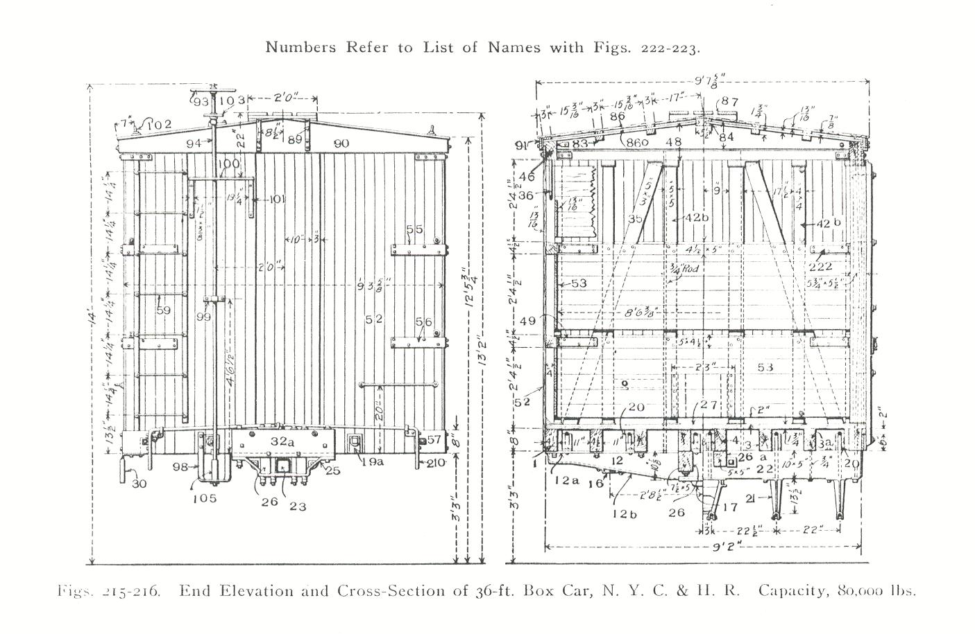

.JPG)

.JPG)
.JPG)
.JPG)
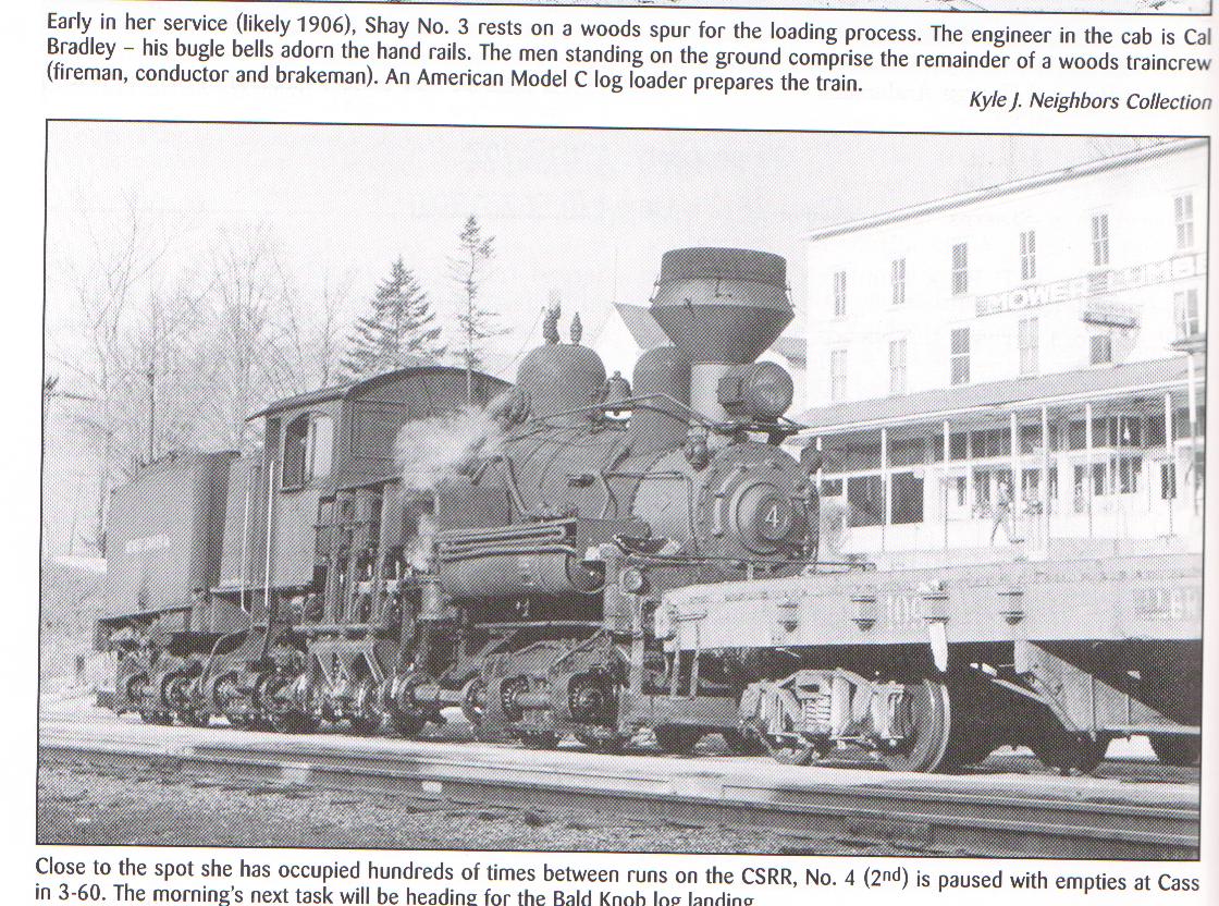
.jpg) 40' Cass Scenic RR Wooden Log Car
40' Cass Scenic RR Wooden Log Car

.jpg)
.jpg)
.jpg)
.jpg)
.jpg)
.jpg)
.jpg)
.jpg)
.jpg)
.jpg)
.jpg)
.jpg)
-Model.jpg)
.JPG)
.JPG)
.jpg)
.jpg)
.JPG)
 D&RGW
Dual Gauge Idler Car (2005, 2009)
D&RGW
Dual Gauge Idler Car (2005, 2009)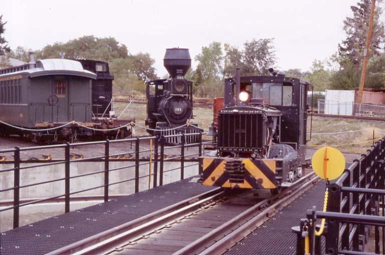


.JPG)


.JPG)

.jpg)
.JPG)
.JPG)