.JPG) 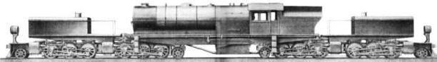 |
|
"Your source for standard gauge modeling in 1:20.3" |
|
|
|
|
||
.jpg) D&RGW
L-105 4-6-6-4 Progress
(updated 11-28-11) D&RGW
L-105 4-6-6-4 Progress
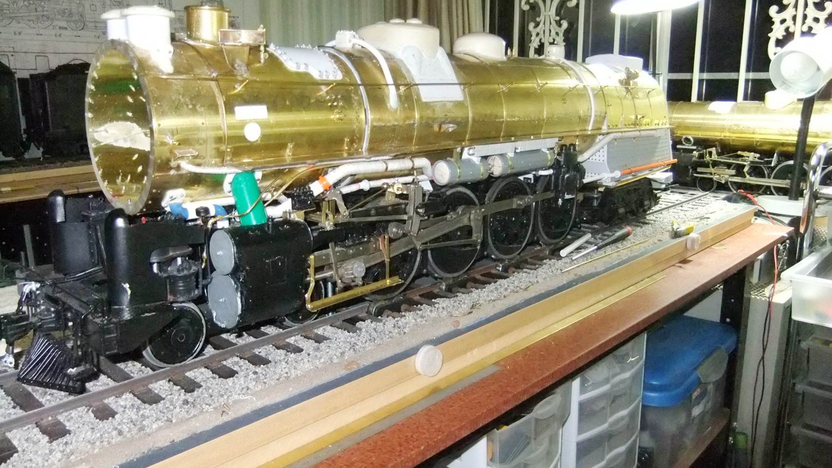
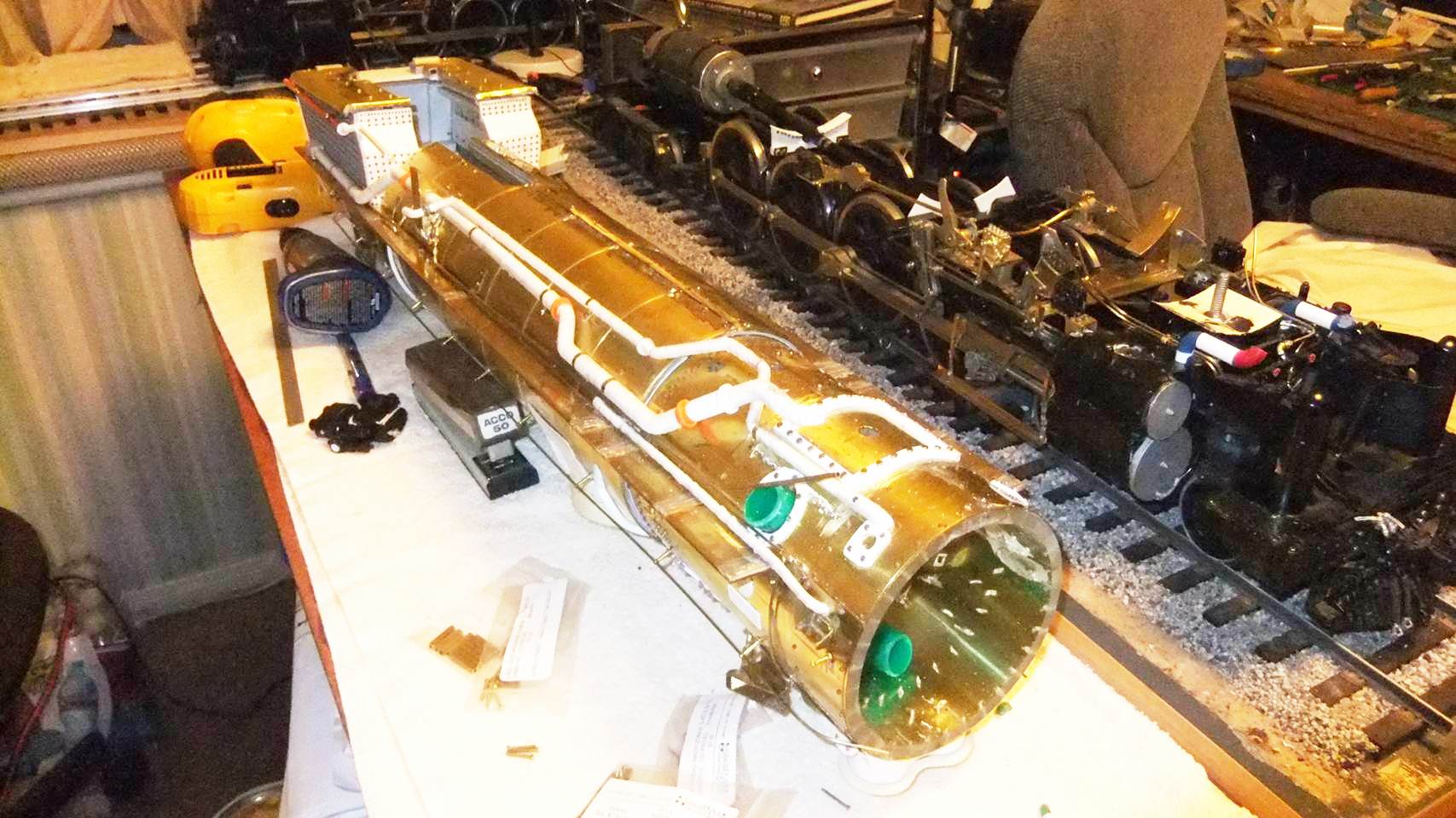
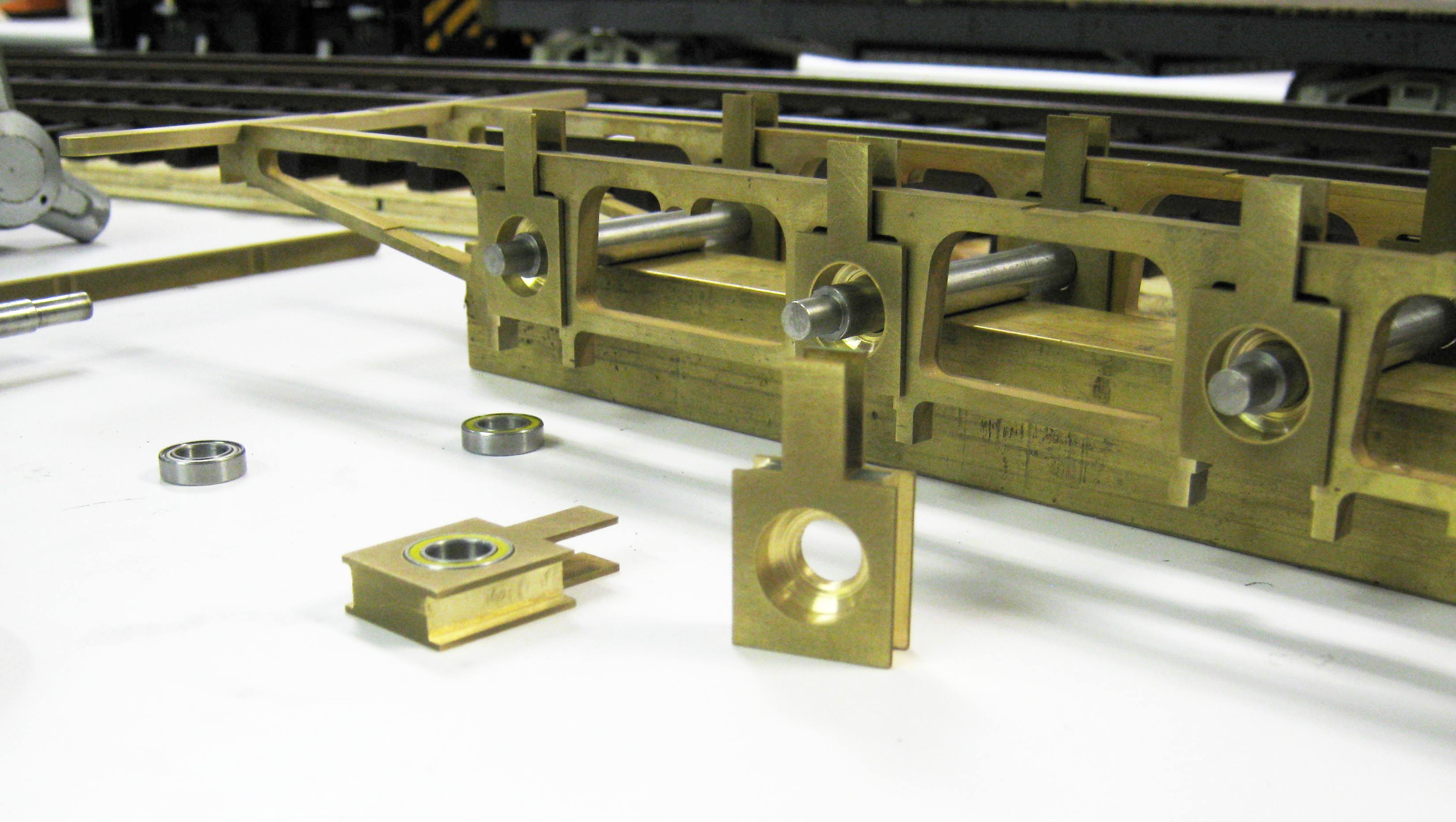
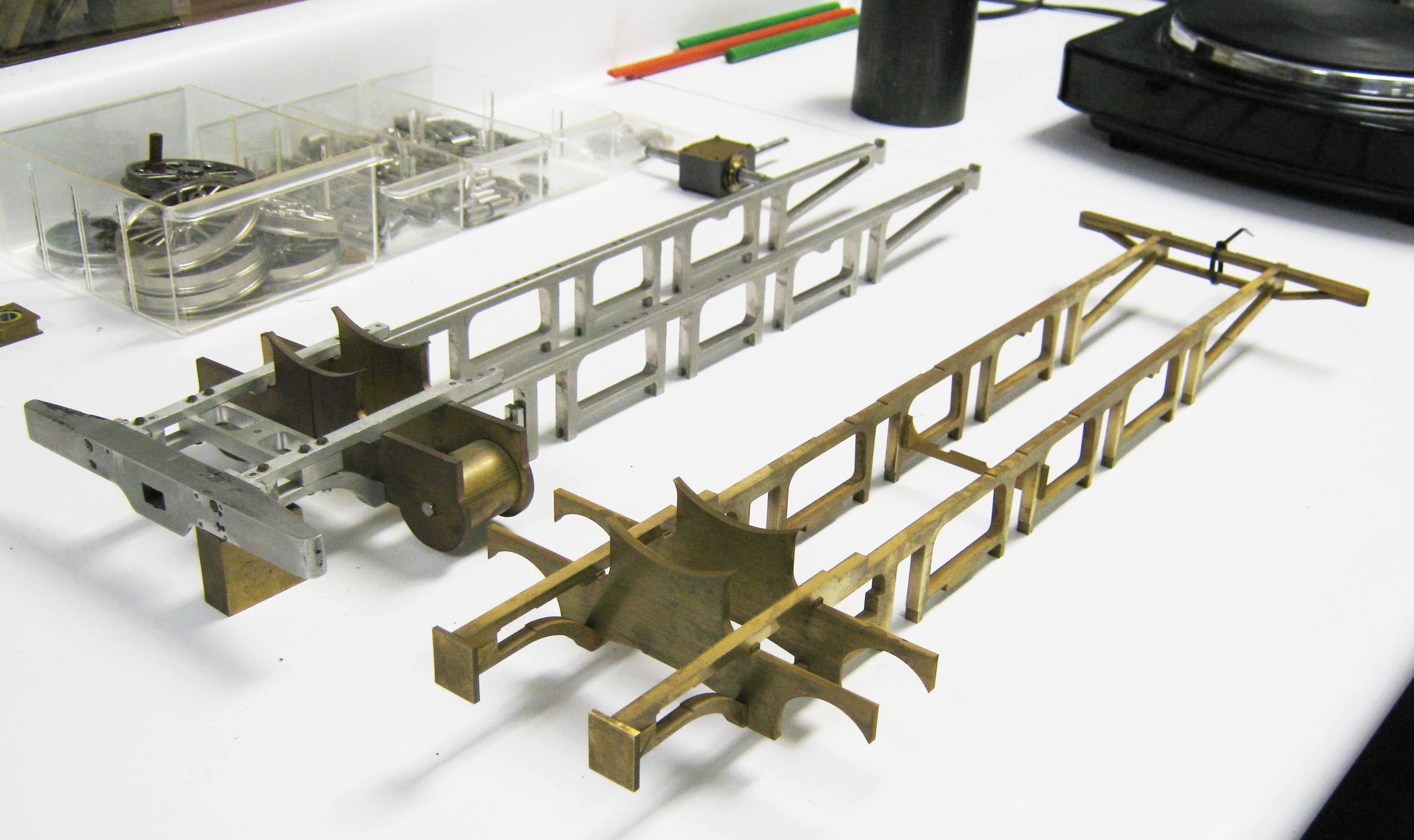
(updated 11-28-11)Much of October I spent working on parts for Doug Hemmeter's D&RGW L-105 Challenger. Here are some of the results.
• Lead Engine Unit CAD
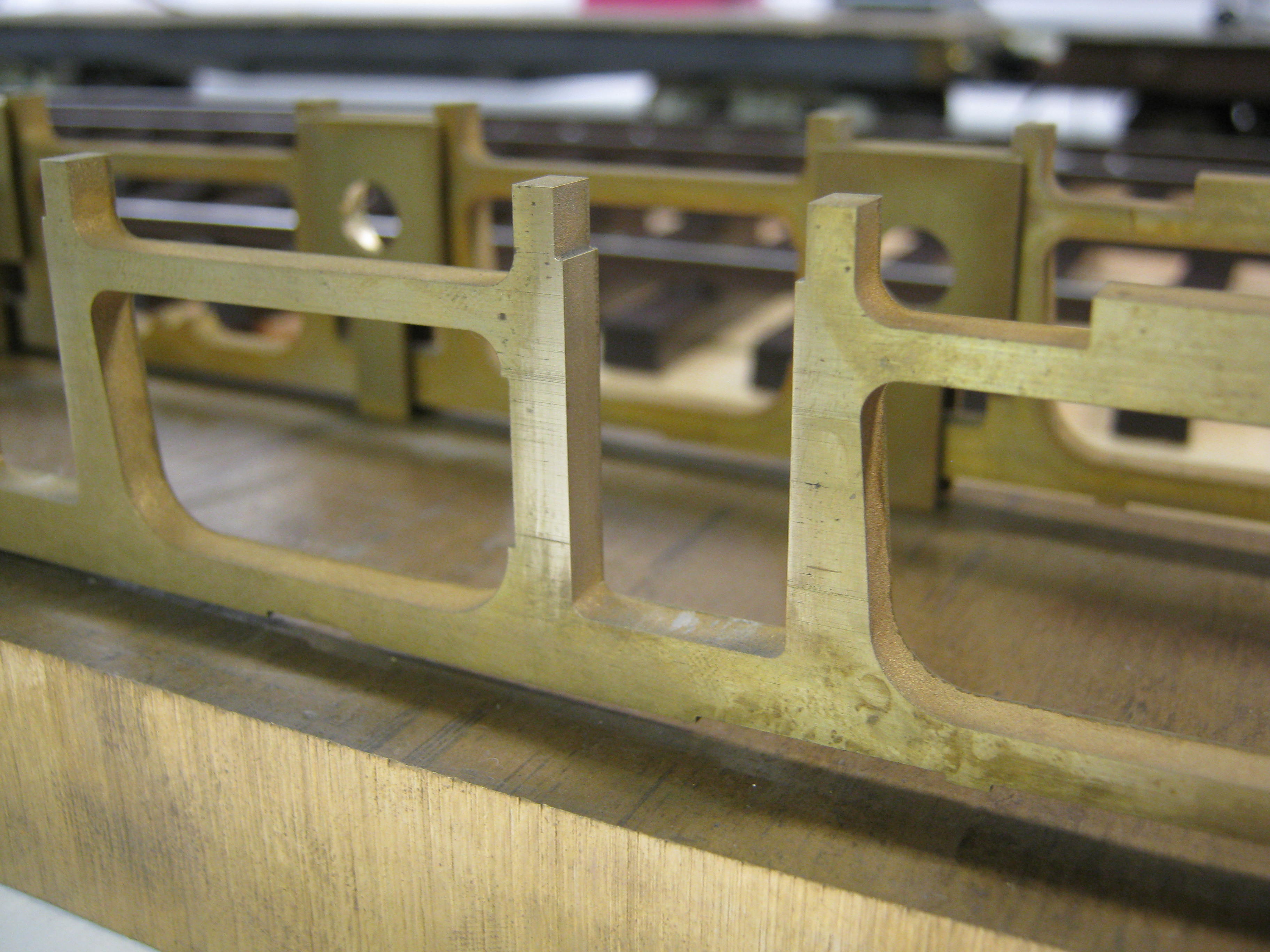
drawings The L-105 was an early
recipient of integrally cast cylinders, frames and valve gear
supports. These massive steel castings were a honeycomb of
pockets, undercuts and cores. Designed to maximize frame
strength and overcome one of the chief maintenance headaches
common to built up frames, integrally cast frames overcame the
natural tendency of bolted together ones to work themselves lose
due to vibration. Out of tram frames mean binds, hot bearings,
and worn bearing surfaces. From a modeler's standpoint, cast
integral frames are difficult to reproduce due to their many cut
outs and undercuts. Even at that, most of the components will
never be seen, so some degree of simplification is necessary. My
design work on the lead engine unit for the L-105 reflects this
reality. Starting with the prototype frame drawing, I first
reproduced the lead engine unit in all its complex glory and
then sought to simplify the model version from it. The image
from my CAD drawing at right is that of the prototype without
allowances for the model. A PDF version scaled to 1:20.32 and
printable on size E paper (36x48) may be viewed
here.
|
||
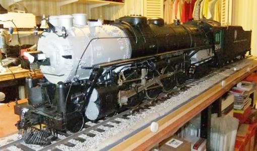 Doug Hemmeter Finishes Second D&RGW M-68 4-8-4 Doug Hemmeter Finishes Second D&RGW M-68 4-8-4
(And Nears Completion on Two Others!) (updated 11-30-11) Doug Hemmeter has been at work on four models of the D&RGW M-68 4-8-4 since about 2006. The first locomotive, #1801, was finished in August of 2009. The second, #1804, in D&RGW black livery, was completed in April of 2011. The two other M-68 Northerns, #1802 and #1803, are in the super-detailing stage and should be done by early 2012. Here's some pics of both 1804 and the remaining two locomotives. Additional photos can be found in Doug's Gallery.
|
||
 1:20.3
Standard Gauge Radius Test
(updated 8-28-11) 1:20.3
Standard Gauge Radius Test
(updated 8-28-11)One of the quandaries that arises when developing a new scale and track gauge is determining what minimum radius various steam locomotives can be designed to traverse and how to do it. Model locomotives are expected to negotiate minimum radius curves proportionally far tighter than their full size counterparts. For instance, if we project up from the smaller scales, a 36" minimum radius in HO scale would be considered quite generous, in fact a necessity for many 10 coupled or mallet articulated locomotive. In F scale, 13 foot minimum radius would be the rough equivalent to 36" minimum radius in HO scale. The engineering question, however, is how to get there. For a Big Boy in F scale or a Santa Fe 5011 series 2-10-4, 13' radius sounds pretty tight. When looking at the layout of that many drivers in a rigid wheelbase, especially larger diameter ones in the 70" to 80" range, then things begin to look almost impossible. Little Engines Gauge 3 live steam 4-8-4s, for example, required a 20' minimum radius. So the question is how can a large scale model be built proportionally to do what a small scale model does, without looking silly or introducing gross compromises.
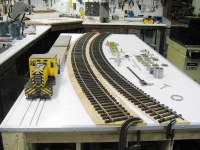
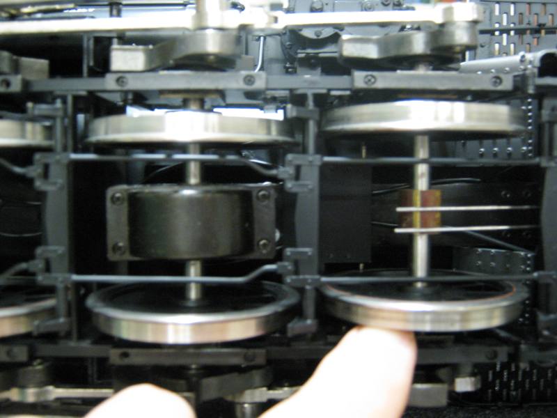
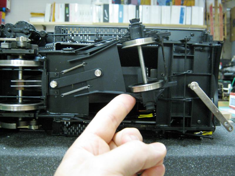
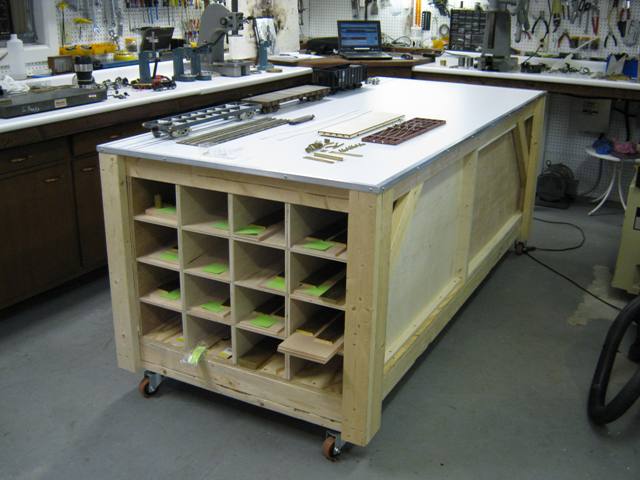
Engineering the L-105 On the the D&RGW L-105 4-6-6-4 (see announcement below) whose chassis I am building for Doug Hemmeter and Gary Bartlow, my goal is to engineer this portion of the locomotive to get around at least a 13' radius curve, maybe even a 10' one. Towards that end I have laid out several test curves on my work bench (above) and begun doing some of the engineering work first in AutoCAD. At this point, my best guess is that 1/8" of lateral play will be required in drivers #2 and #5. Mounting the boiler at two pivot points above each engine unit, in the style of a Garratt rather than a mallet articulated locomotive, will also be needed to enable this massive six foot long model to negotiate so narrow a curve--and not look silly in the process. Remember, these big F scale models are being built to run, not just sit on a shelf and look pretty. Further engineering and developmental work is being done on on one of my own models (below). |
||
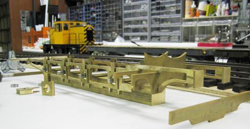 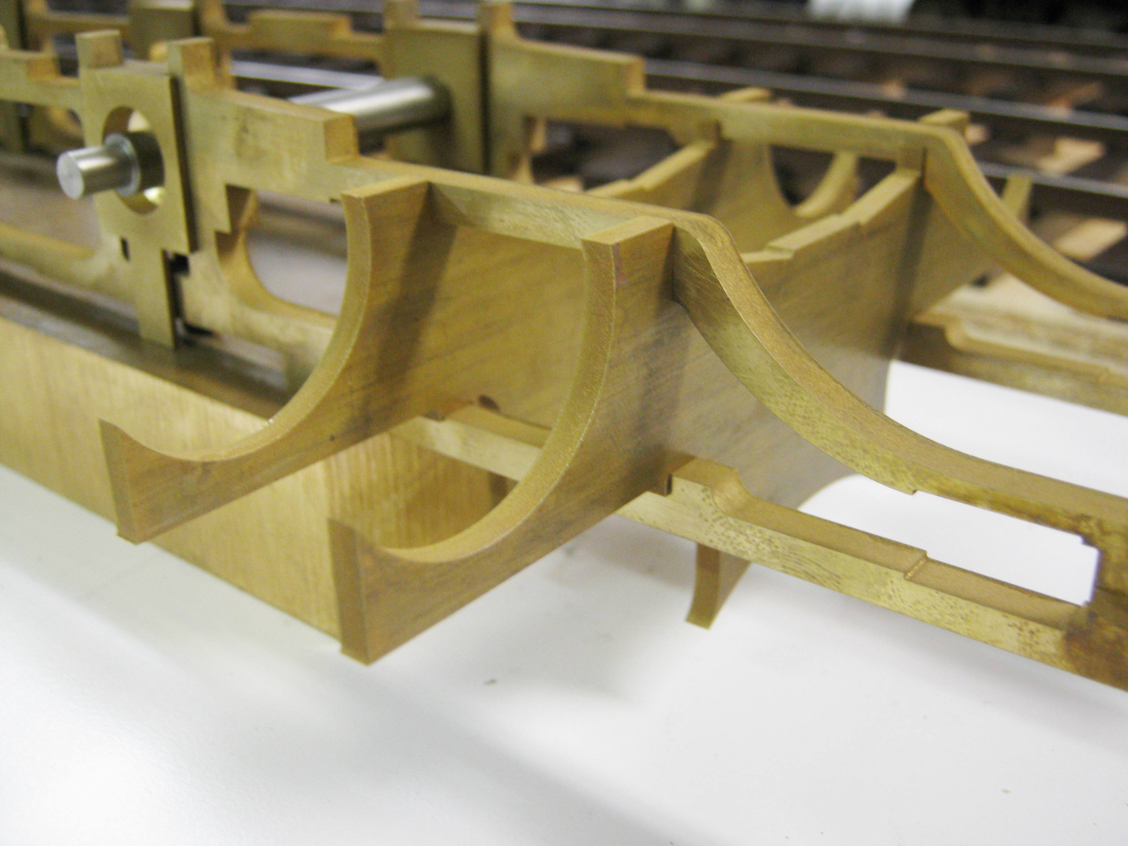  %20045.jpg) %20006.jpg) Brass
2-8-0 Frame Takes Shape
(updated 8-30-11) Brass
2-8-0 Frame Takes Shape
(updated 8-30-11)
Before
I cut metal for the L-105 frame, however, I want to test this
amount of play on
some of my own equipment; and towards that end, I have once
again
|
||
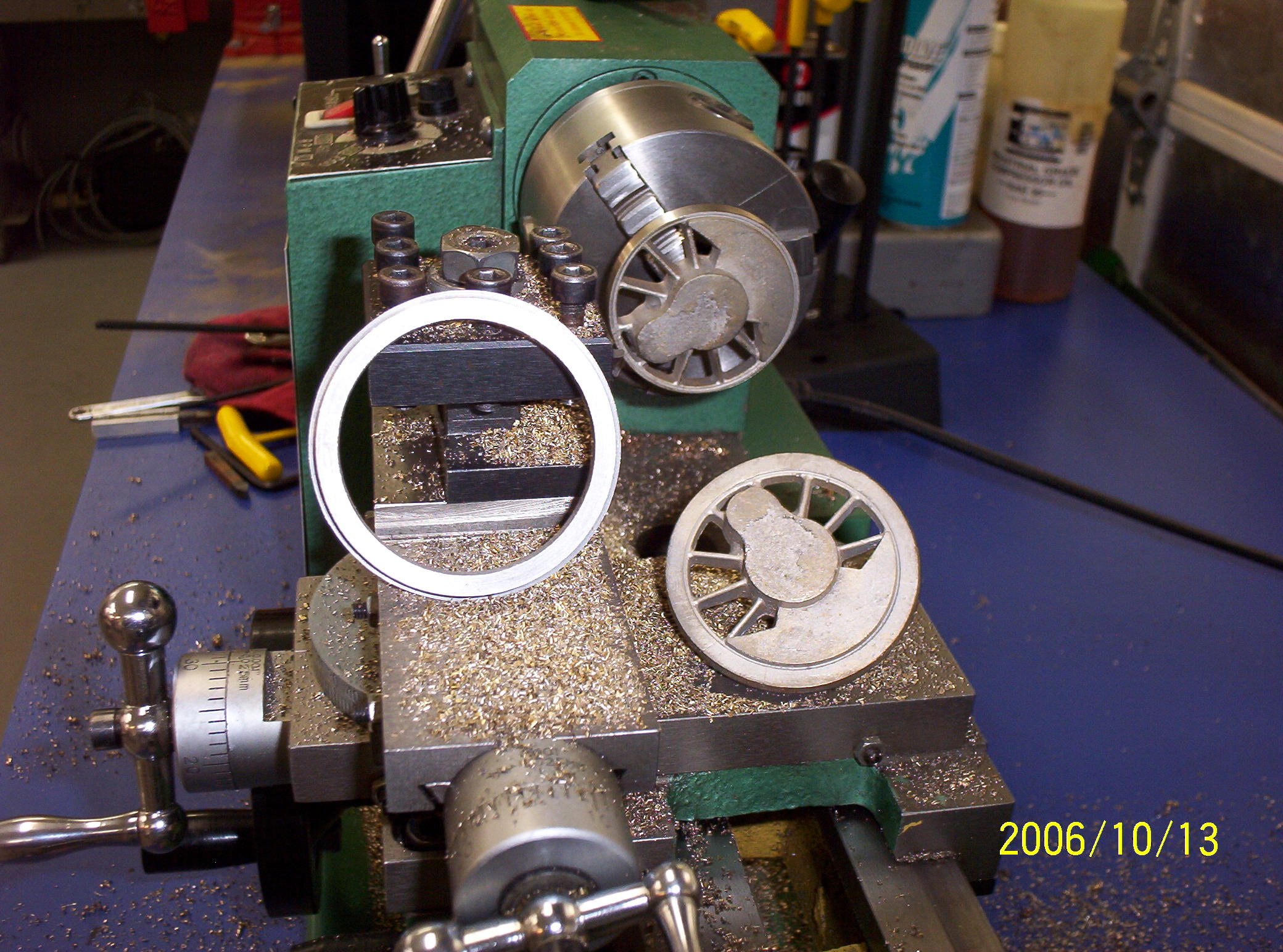
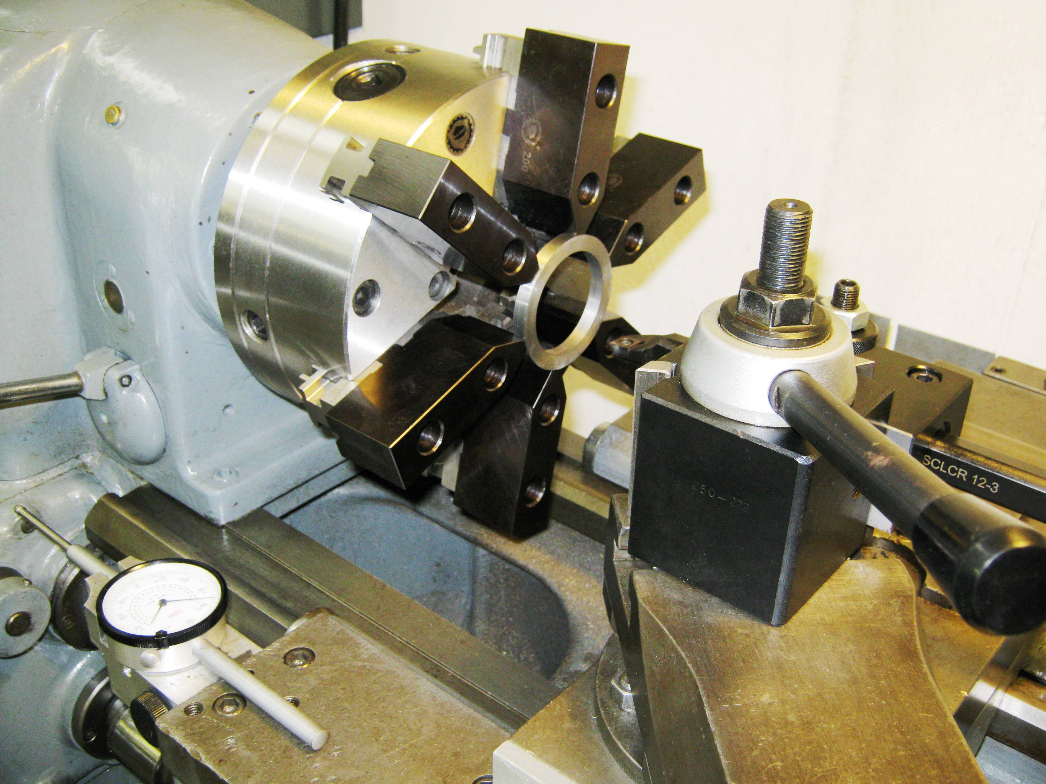
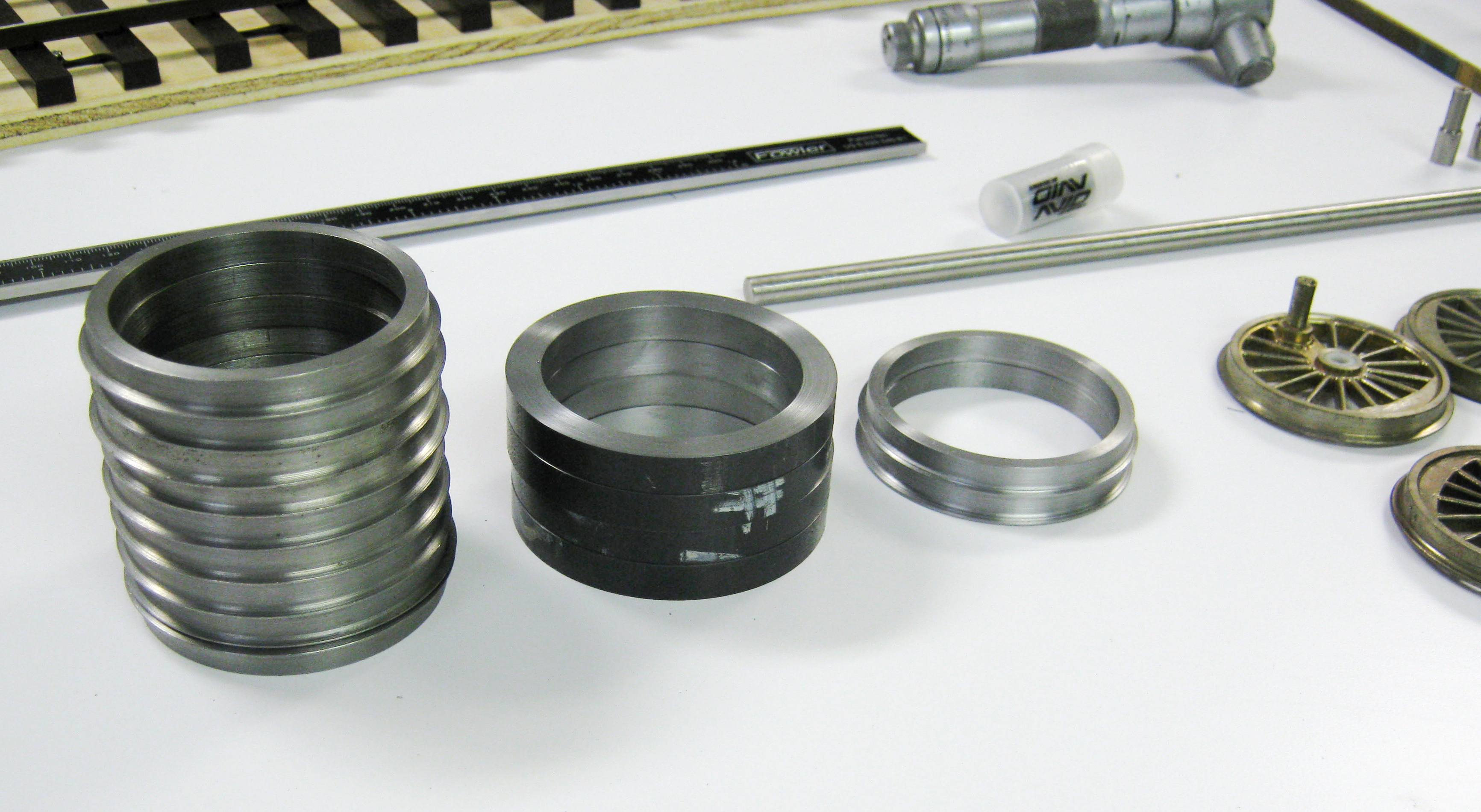
 Driver
Machining
(updated 8-31-11) Driver
Machining
(updated 8-31-11)
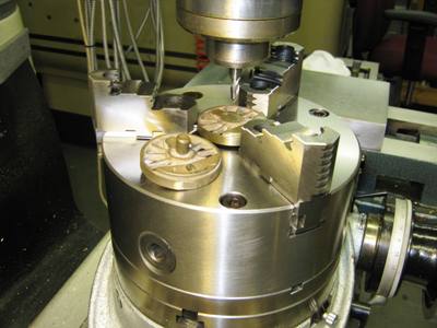
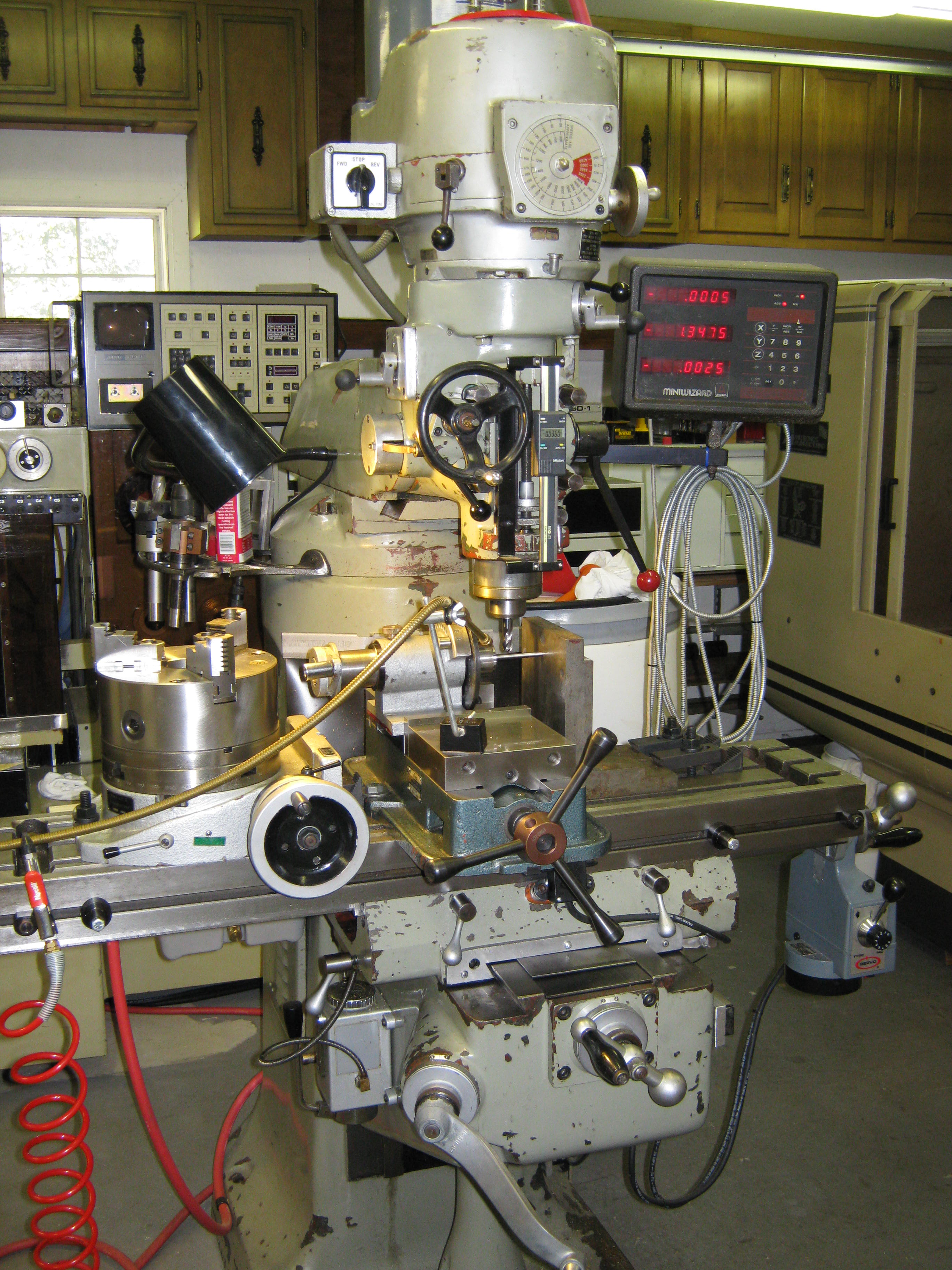
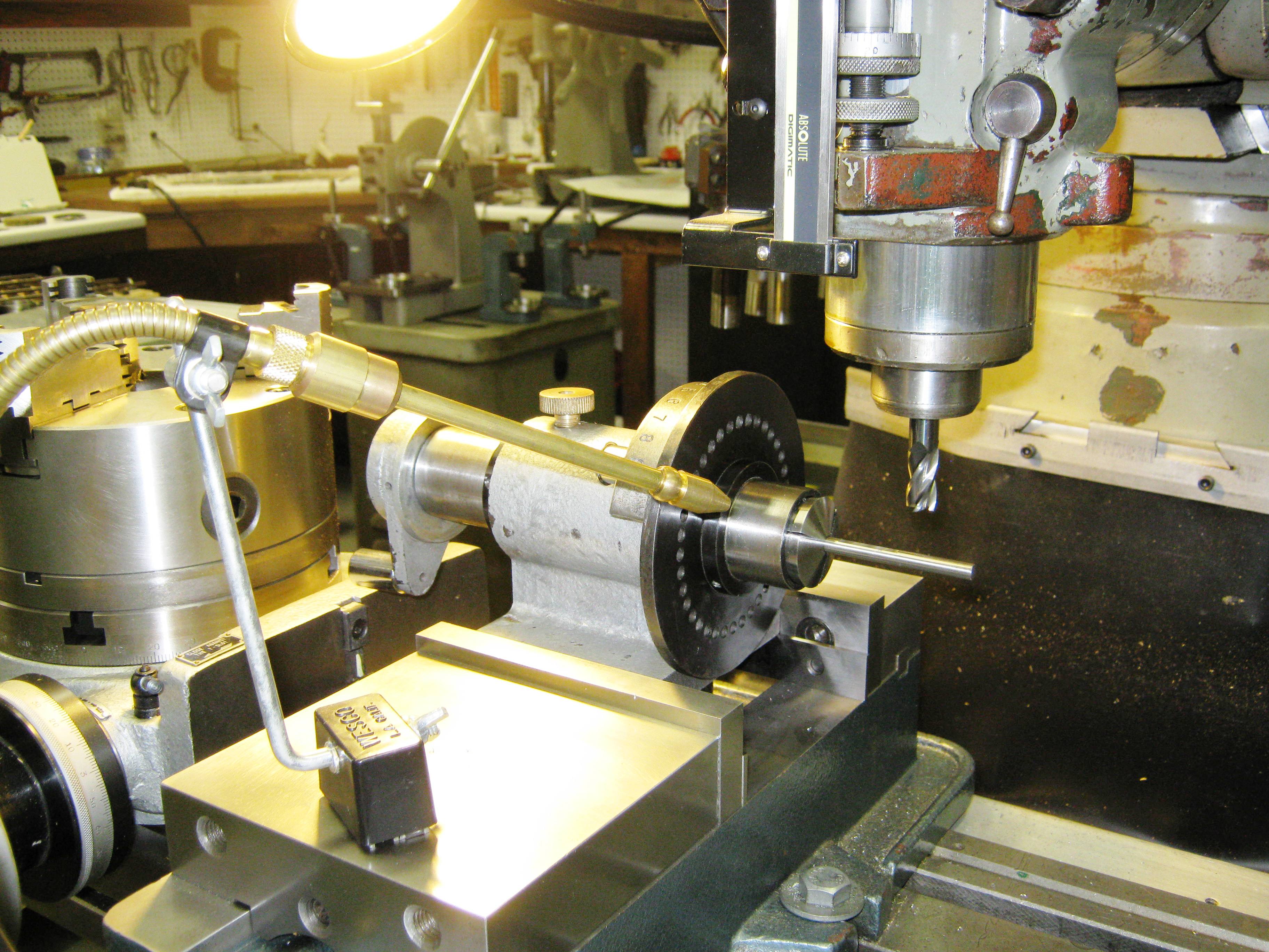
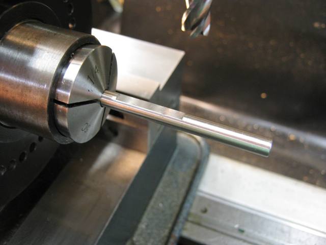
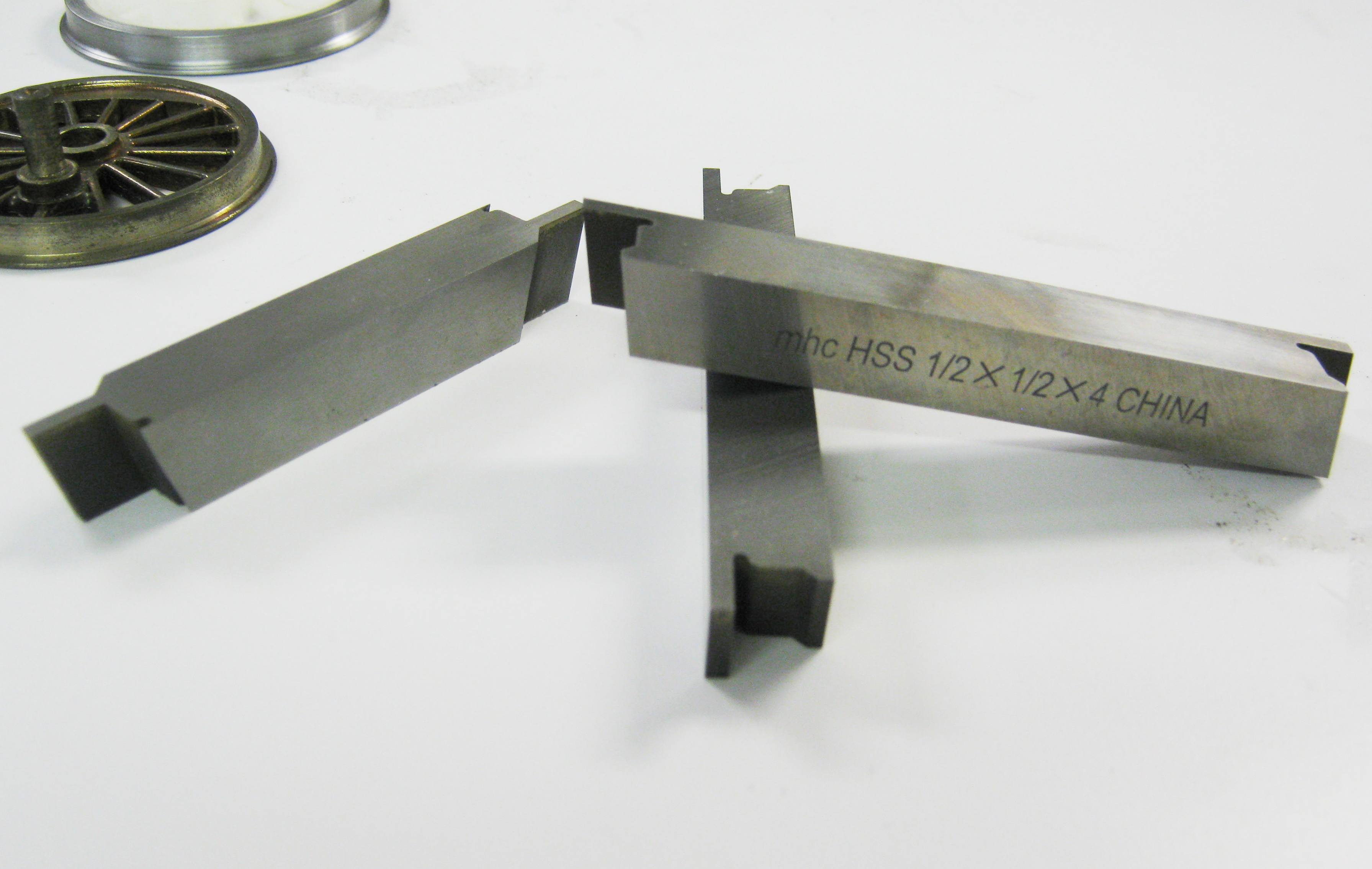
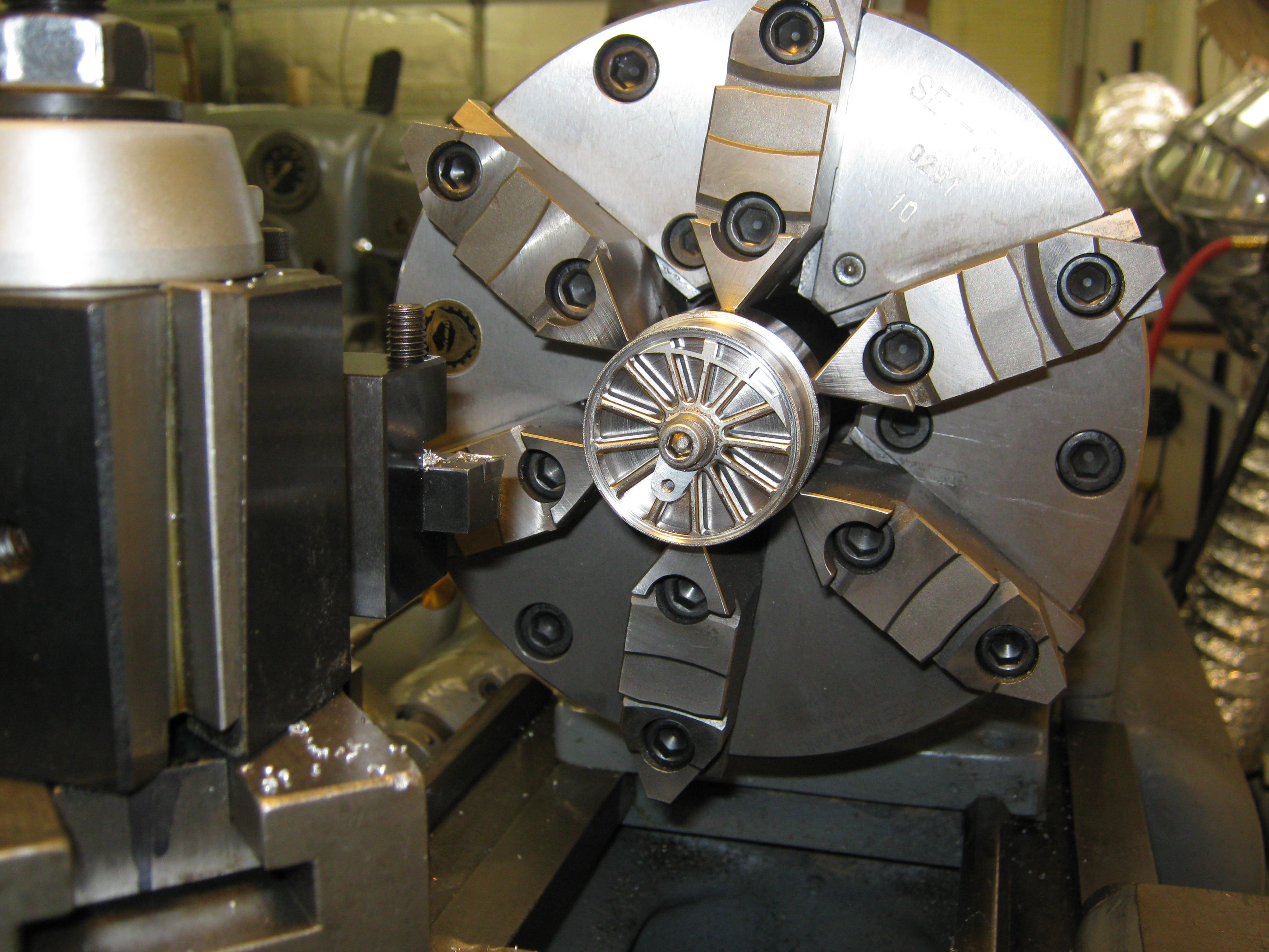
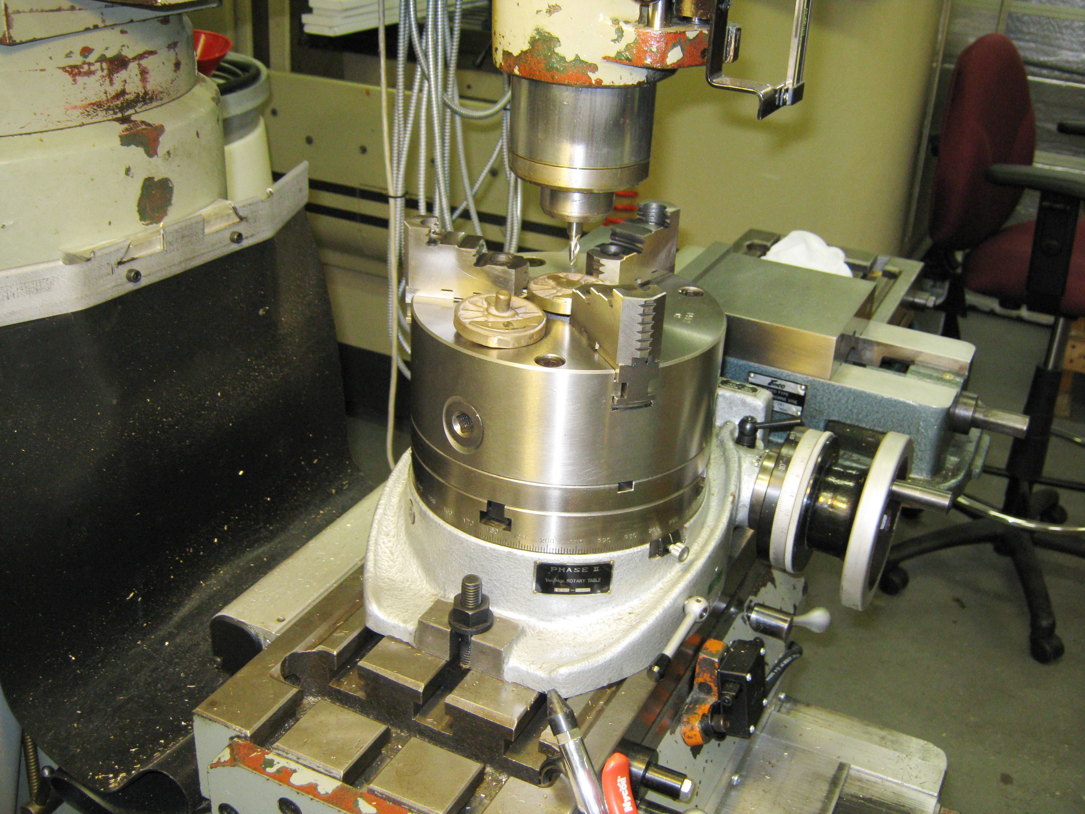
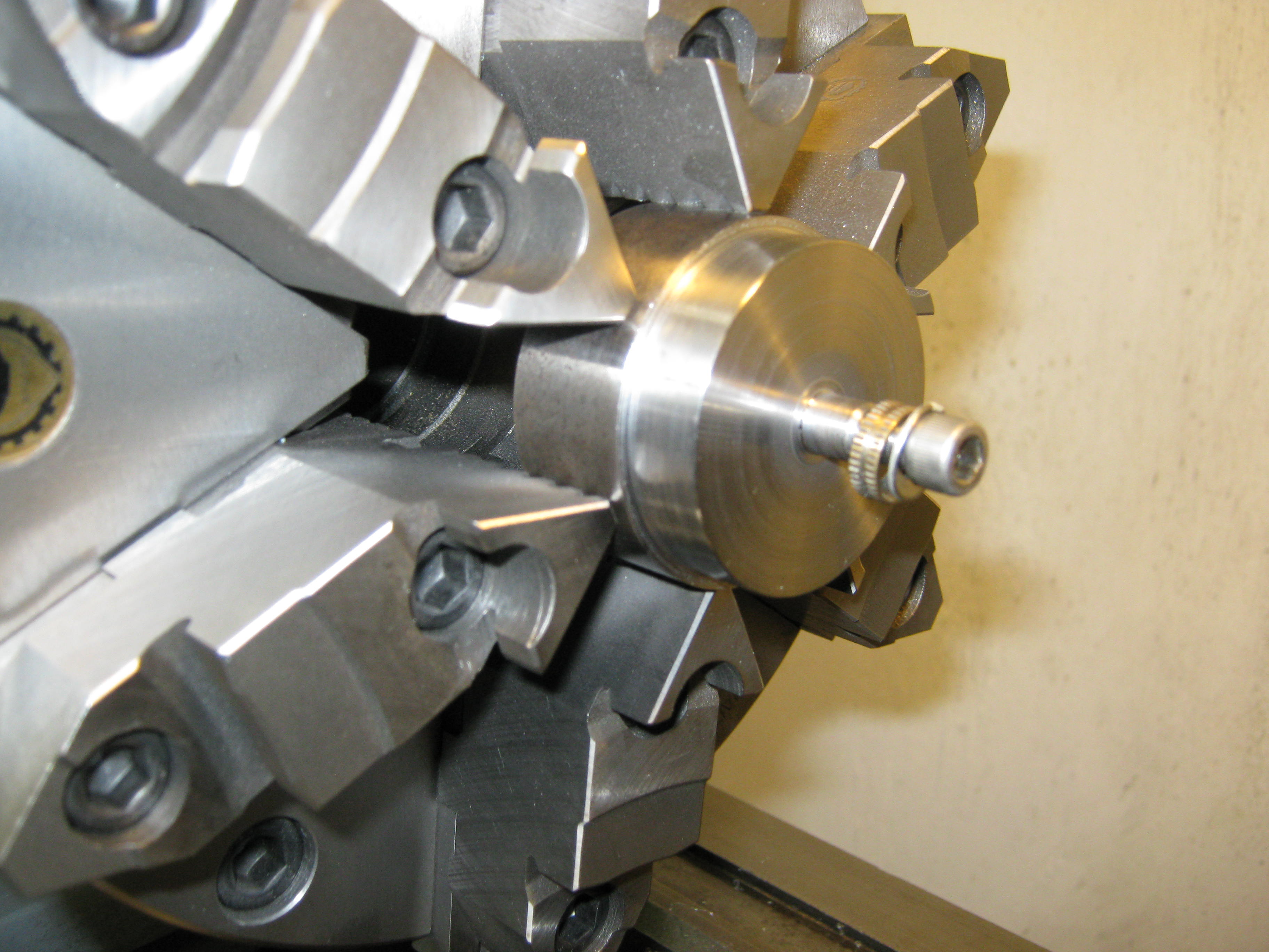
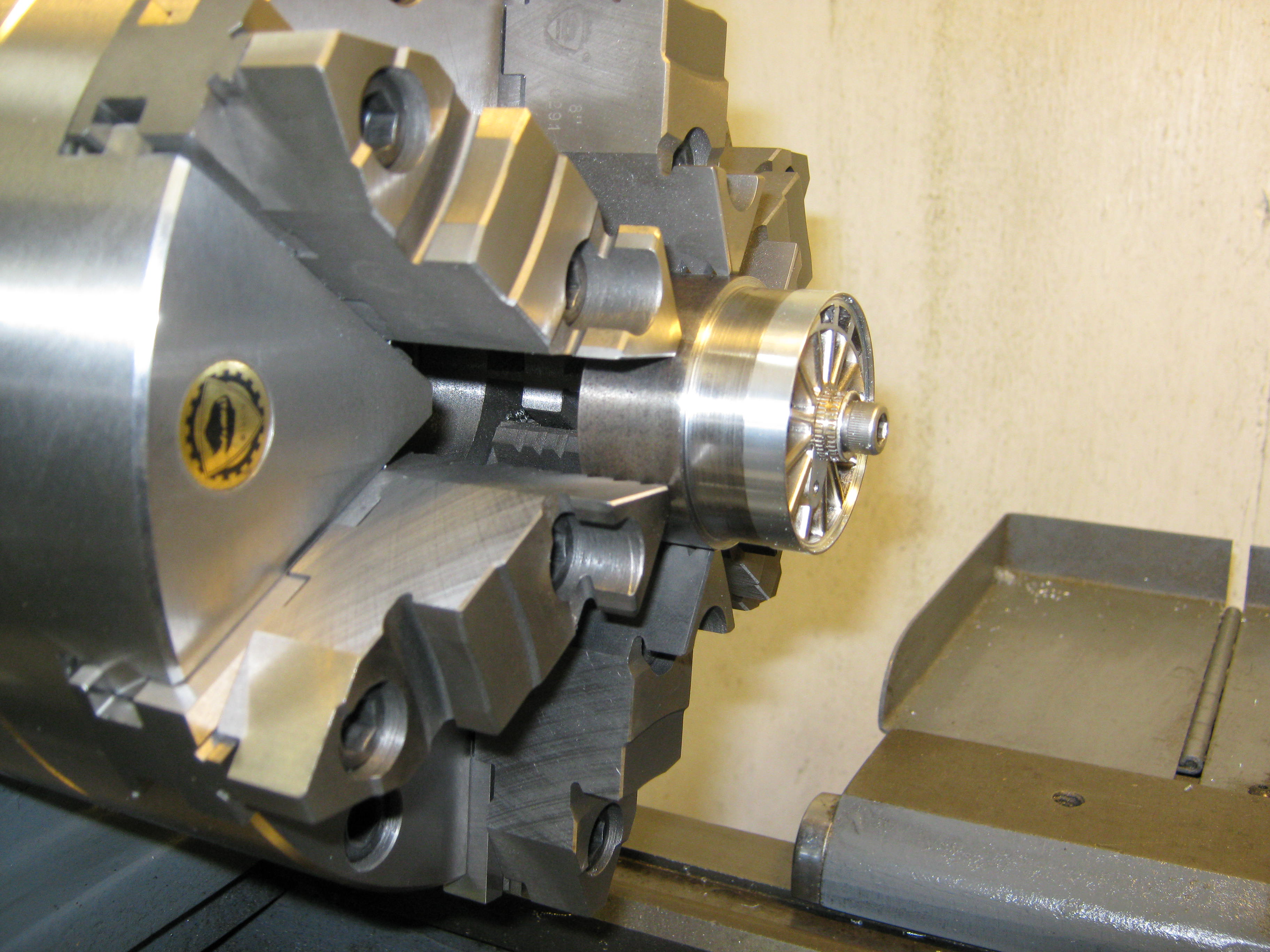
For those of you just itching to turn your own wheels and tyres, and you have a rigid enough lathe, these same 1/2" square profile tools are available upon special order.
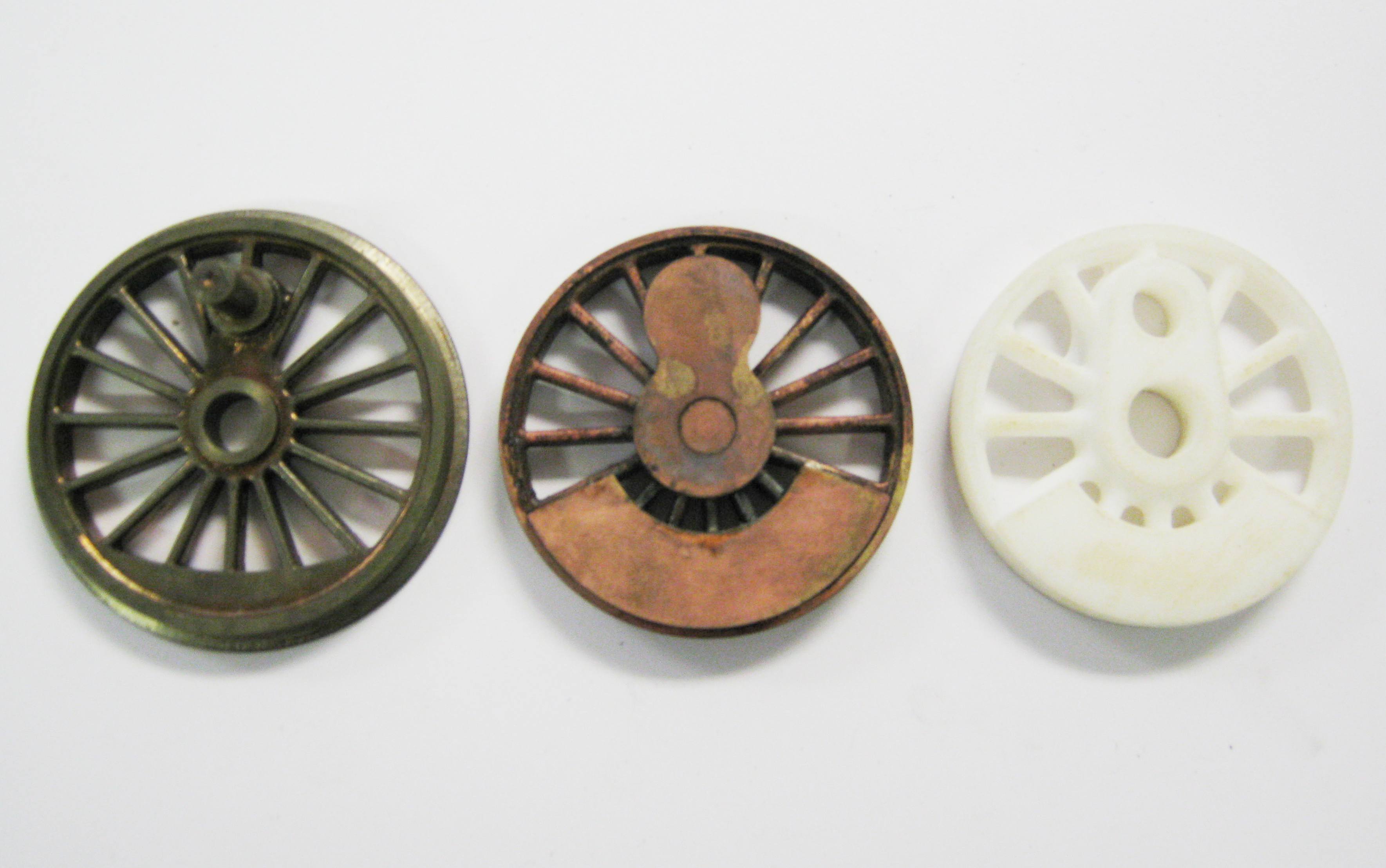
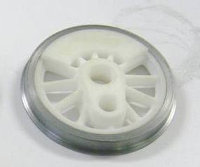
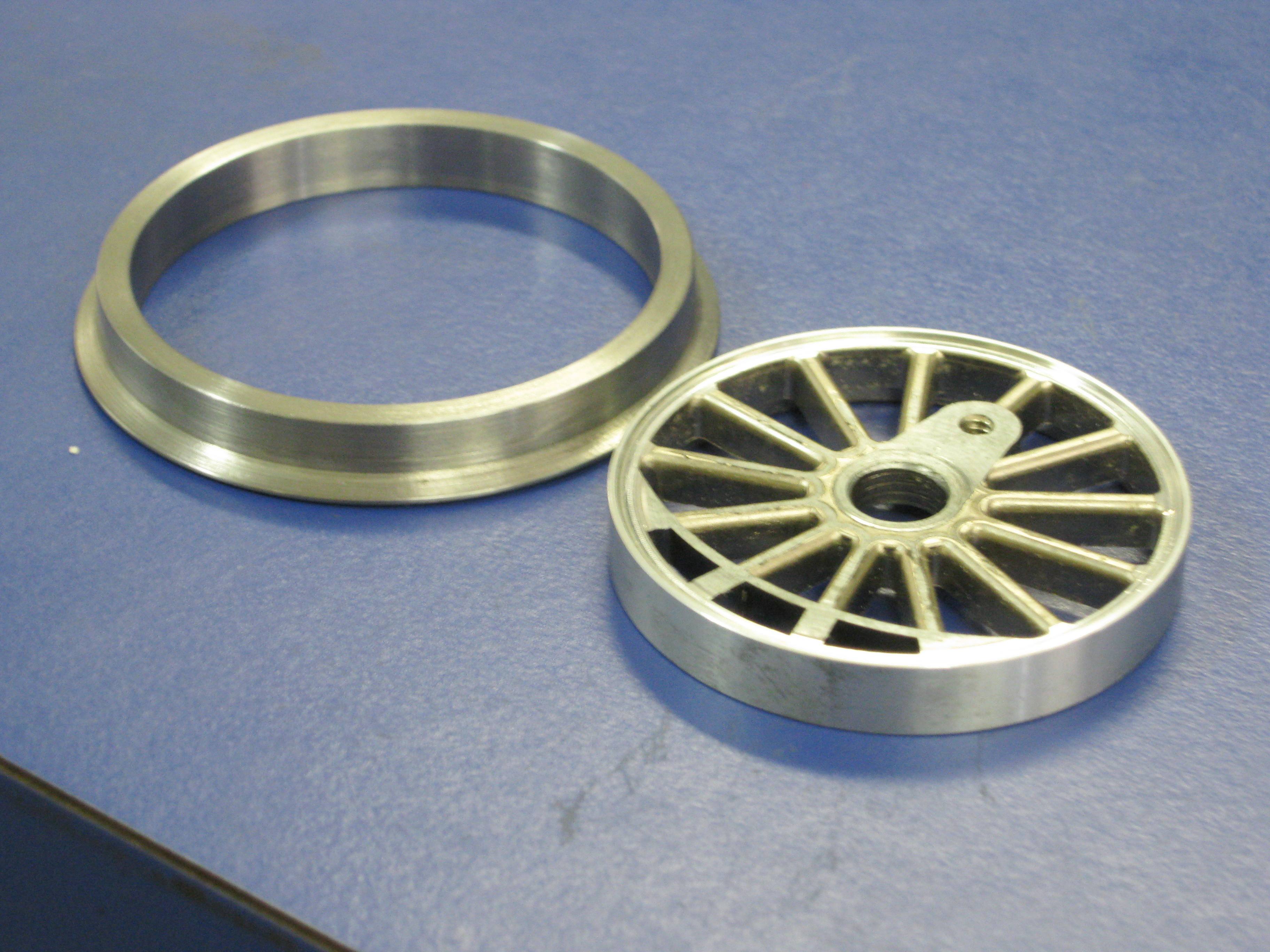
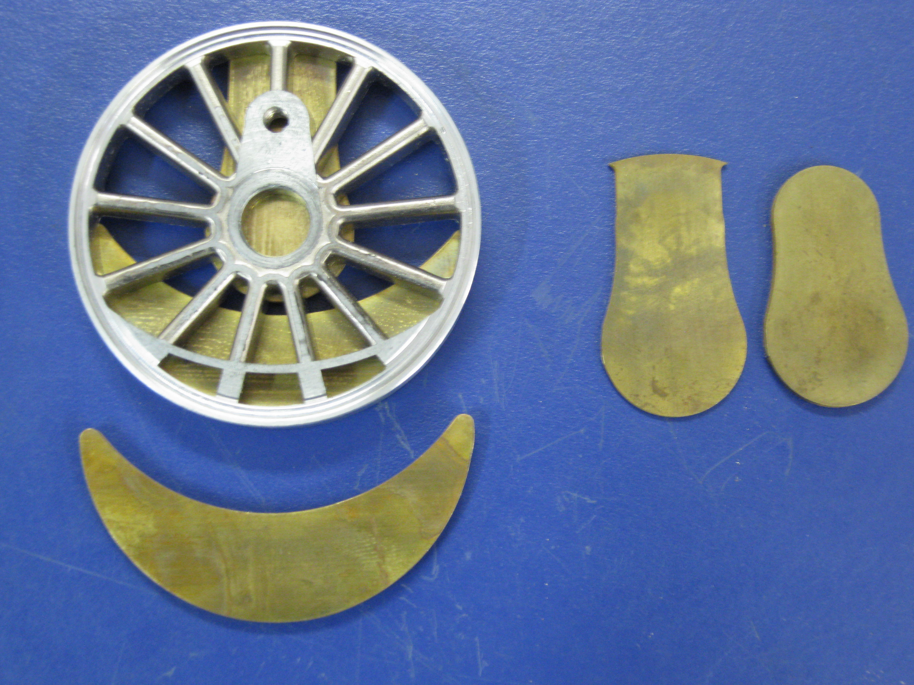
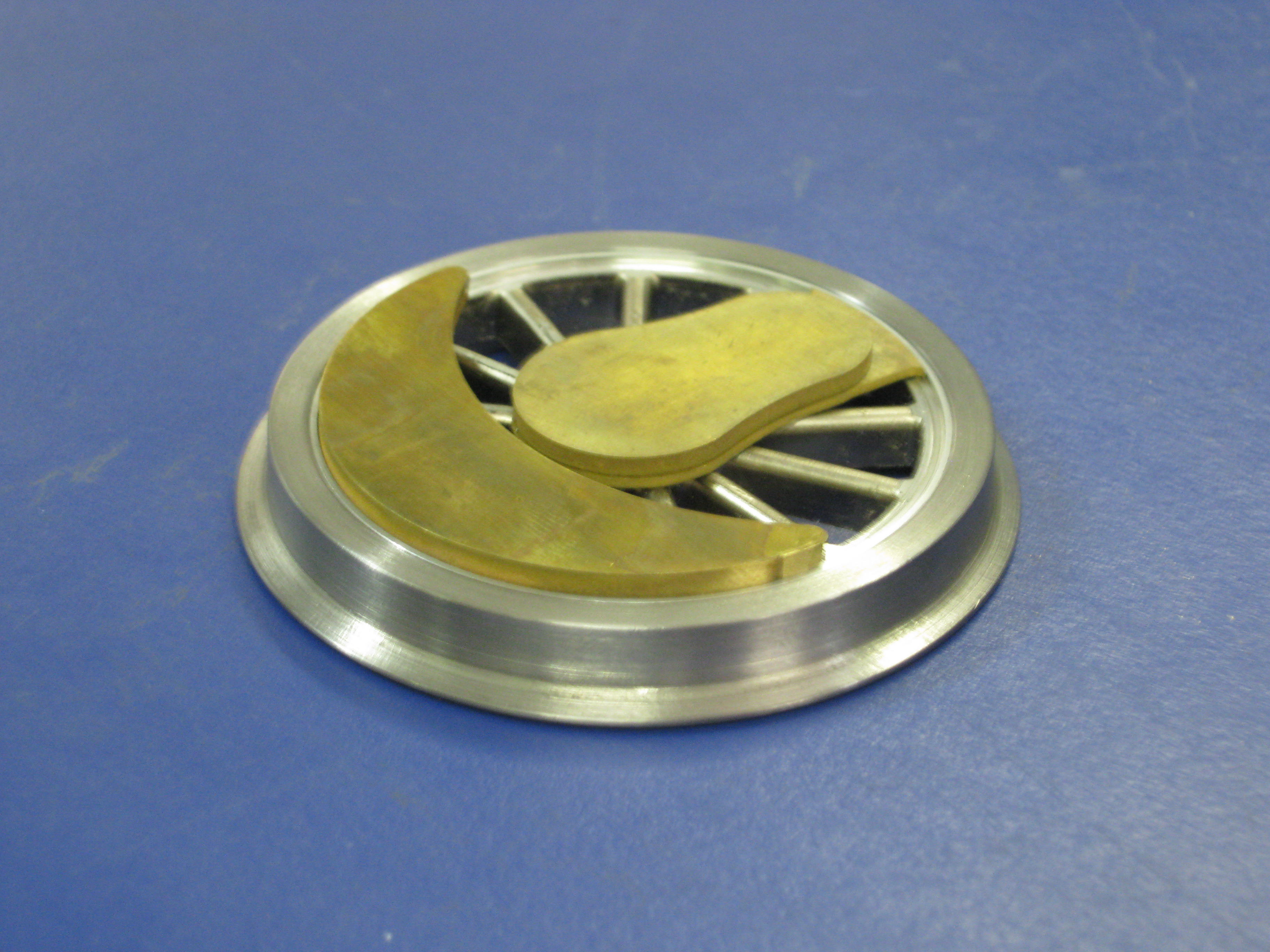
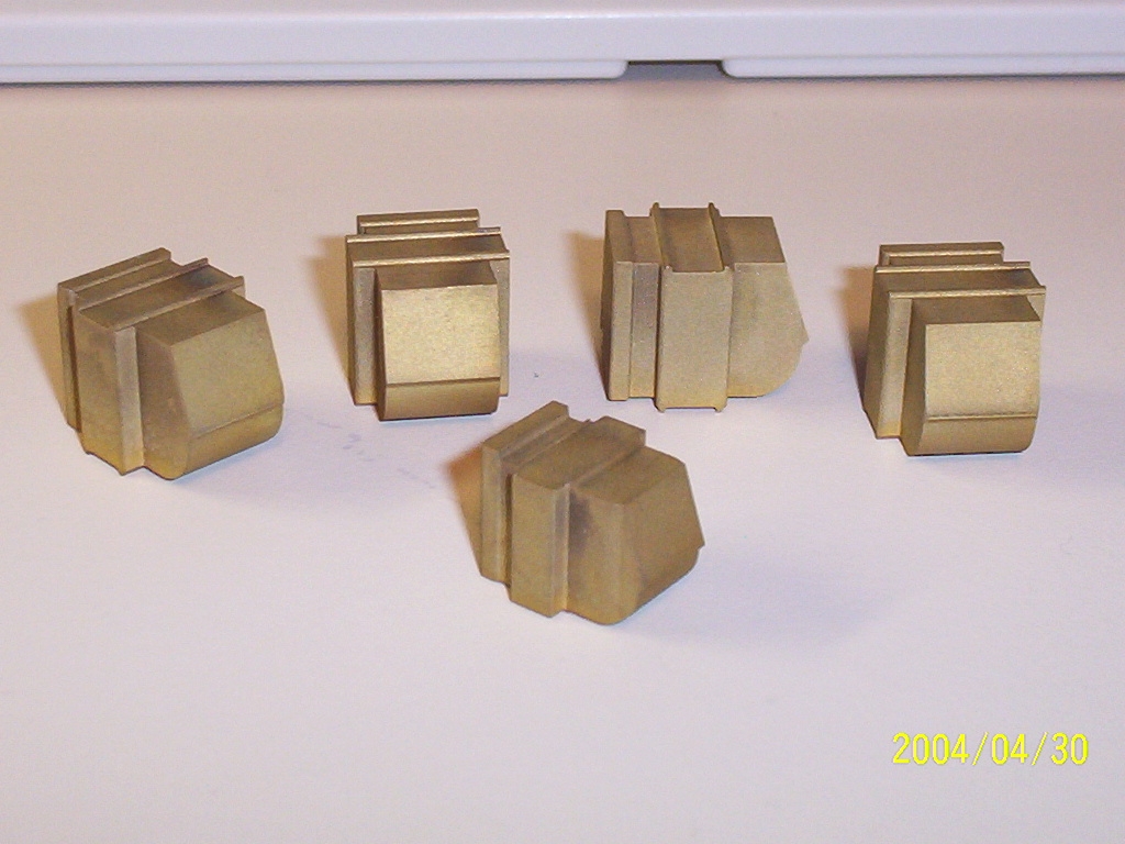
And so the 14 copies of the Palacina Driver center are now being modified to approximate the block counterweight G-Class driver. The Palacina copies are first turned down on a specially made mandrel (since they have no cast-on-lug in the back for grasping with either a collet or a six-jaw chuck. Next new brass counterweights and crankpin hubs are soldered on. Finally, the crankpin and axle holes are drilled and reamed for each driver center in a rotary table on my Bridgeport type mill. The last pic above is a comparison of the Palacina copy, a reworked center, and an ABS rapid prototype of the G-class driver center based upon a SolidWorks 3D CAD drawing. Ultimately a new casting pattern will be CNC machined in accordance with the SolidWorks 3D model--maybe even production ones will be made this way.
|
||
.jpg) 30
Ton 5'-0" Archbar Truck Update
(updated 9-7-11) 30
Ton 5'-0" Archbar Truck Update
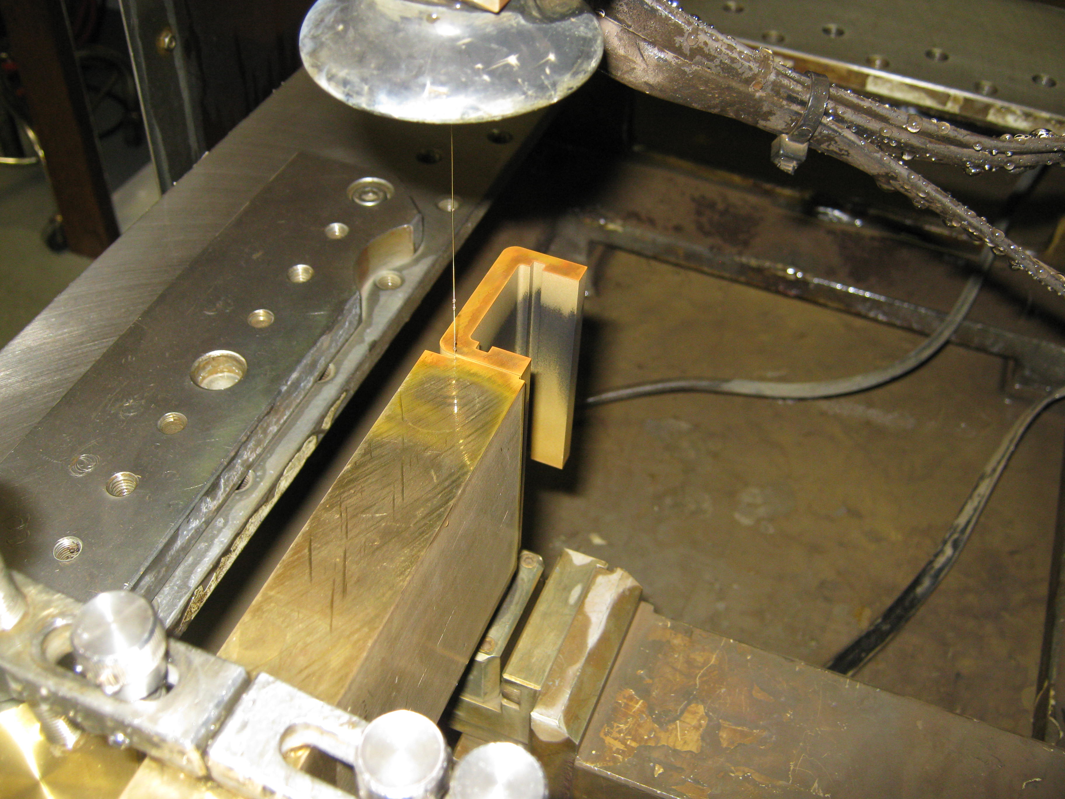
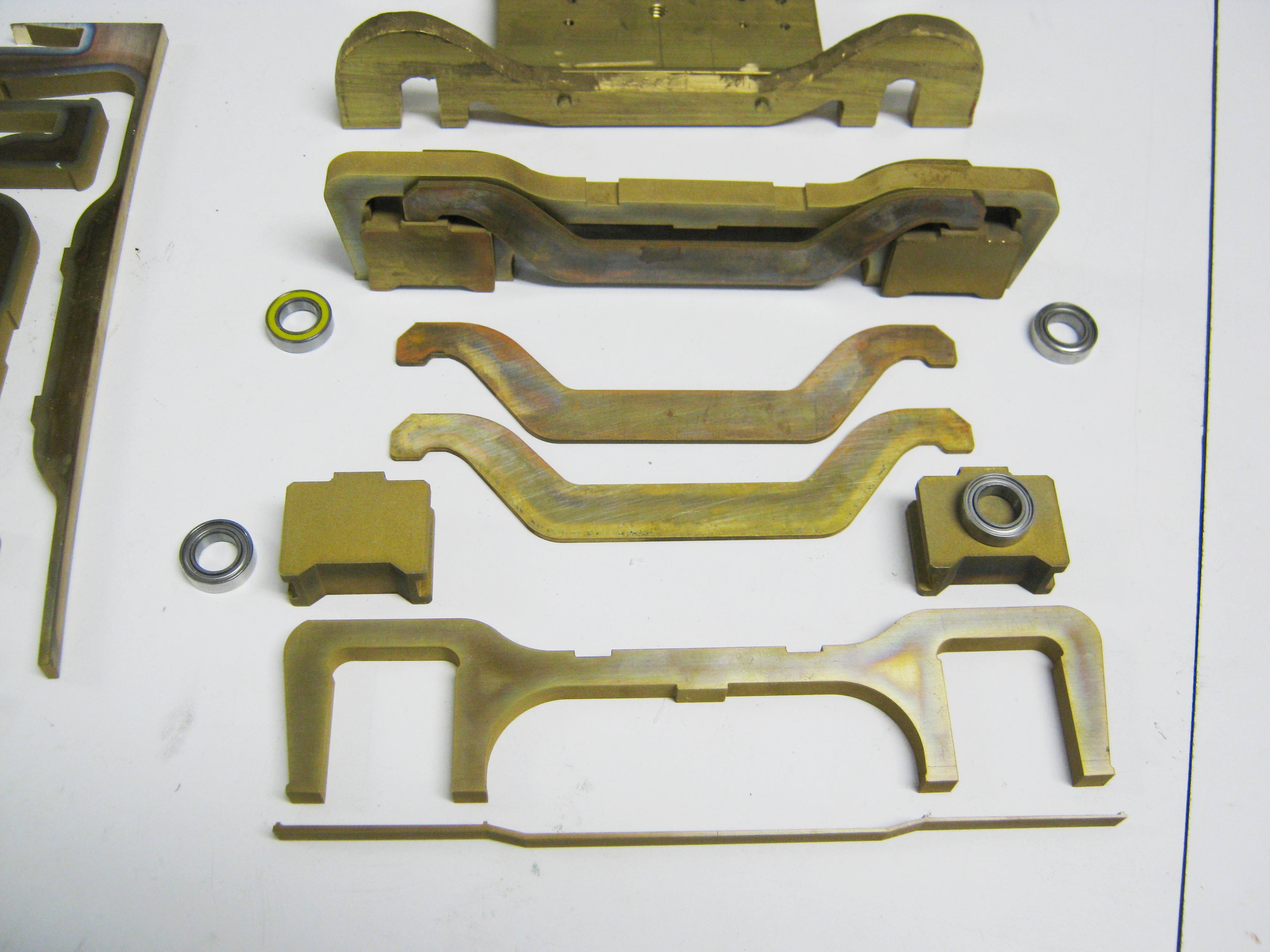
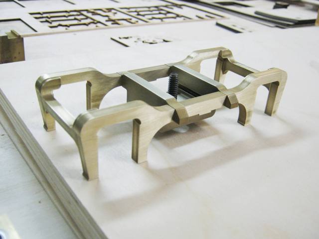
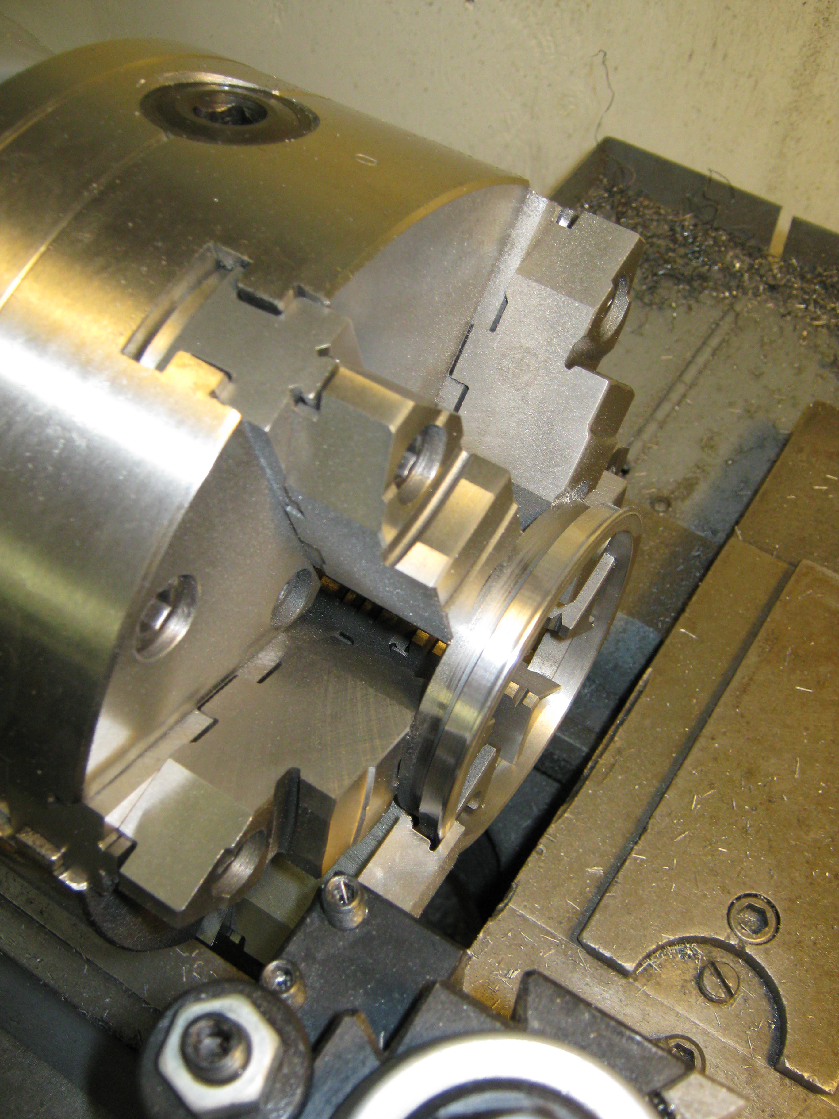
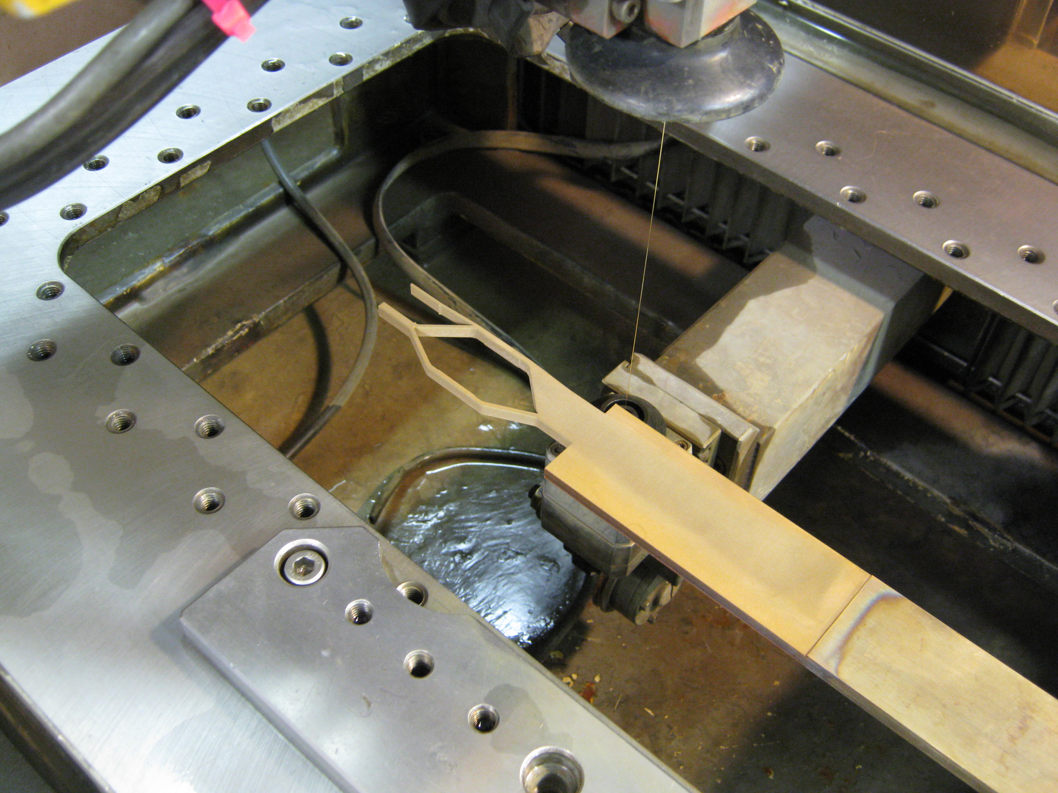
(updated 9-7-11)Here's a look at the progress I have made in pattern making for the 30 ton archbar trucks introduced below. These are being made 2% oversize with the specific goal of casting them in white metal (rather than the 4% oversize ones below which are being made for investment cast brass). Don Niday will be marketing these as part of his Iron Creek Shops product line. Bob Hartford will be doing the actual spin casting in his own North Carolina workshop. Remaining work to be done on the patterns include the addition of square head shoulder bolts and nuts, centering plates, "pods" for the truck springs, brake rigging, and soldering of the assembly. Nearly all parts were cut on my Japax wire EDM. Don plans to have the pattern and maybe the first production trucks at the 2011 National Narrow Gauge Convention in Hickory, North Carolina later this month. Most recent pictures show several of the pattern parts soldered together and assembled as of September 7th, 2011.
|
||
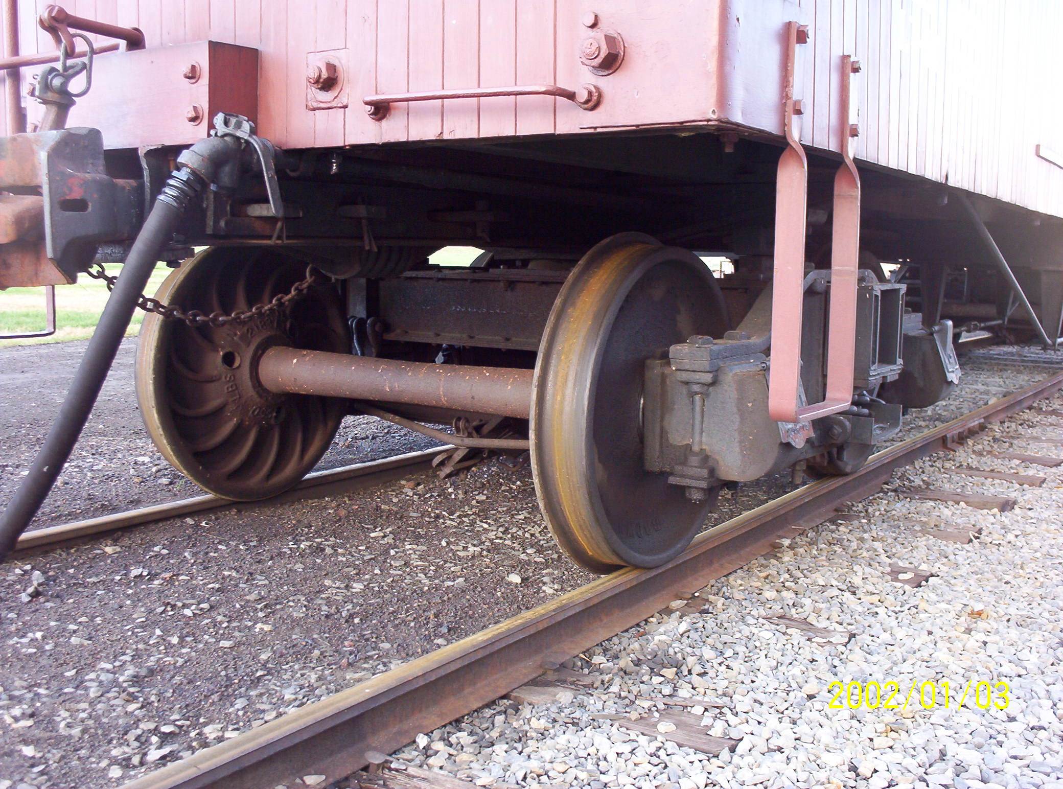
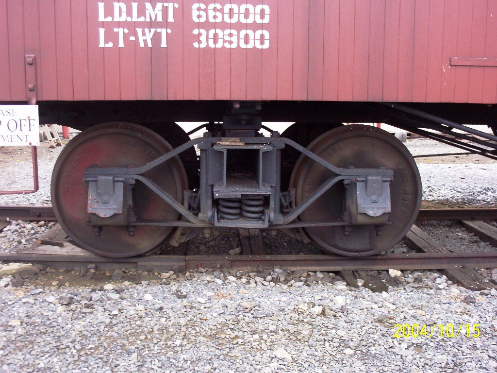
.jpg) 30
Ton Archbar Truck Casting Patterns
(updated 2-23-11) 30
Ton Archbar Truck Casting Patterns
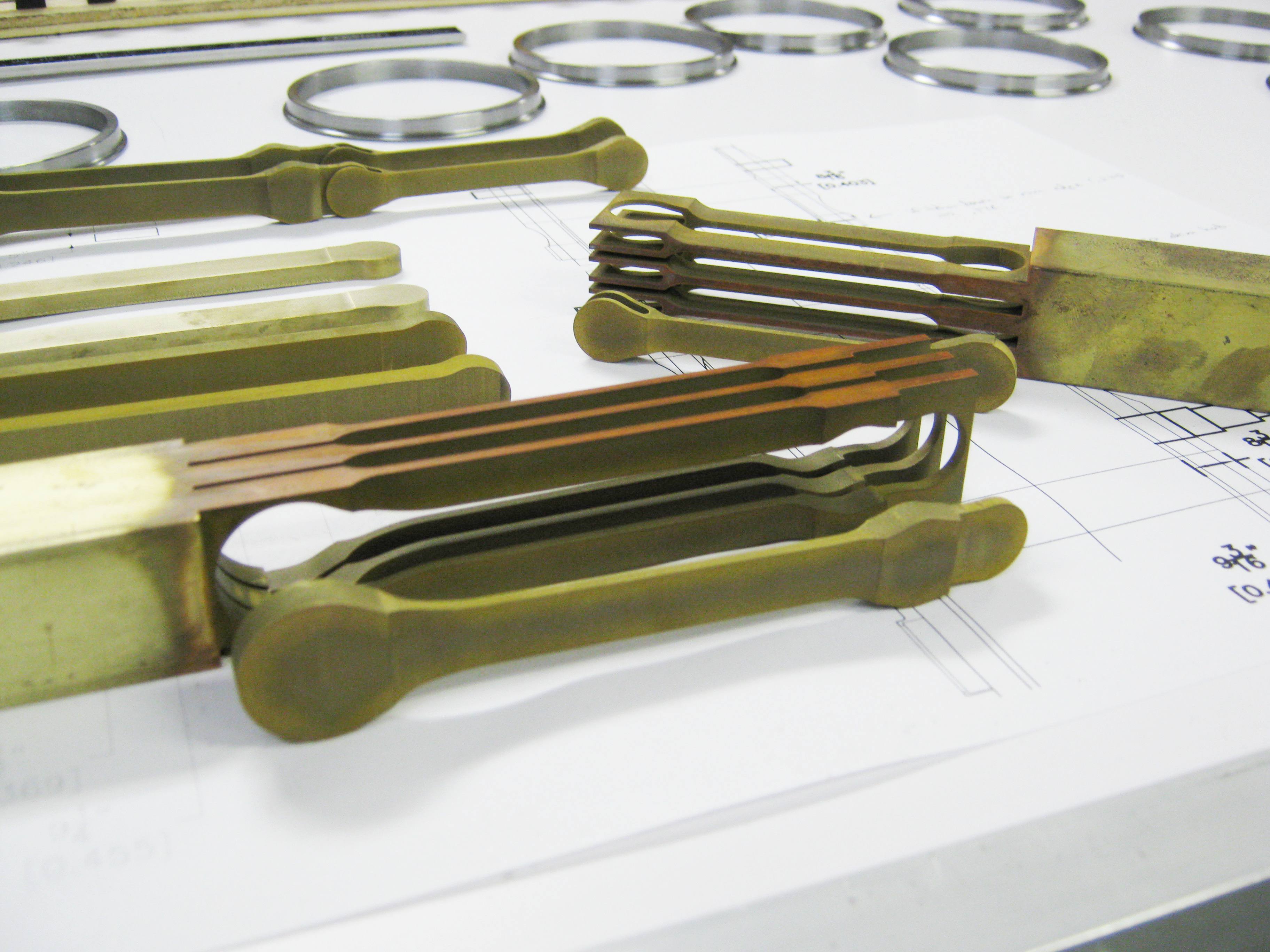
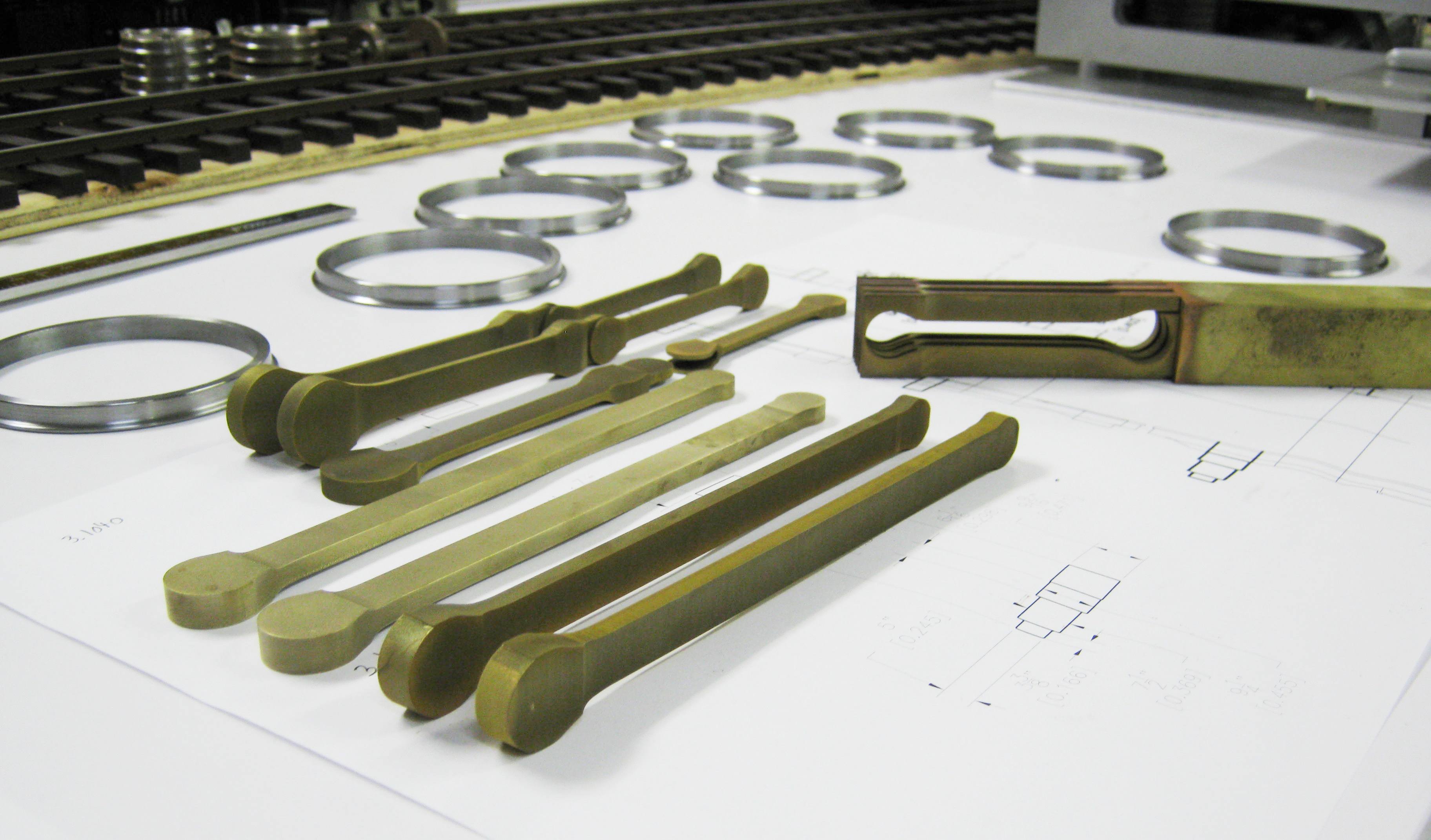
(updated 2-23-11)In 2004 and 2006 my former denomination's presbytery met in Lancaster, Pennsylvania--just a few miles from the Strasburg Railroad and the Railroad Museum of Pennsylvania. Of course, with that many trains and the lure of a Norfolk and Western M-Class "Mollie" being kept hot for the day's run to Paradise, well, what red-blooded steam enthusiast could resist? So after the last session of Presbytery, I hustled down to Strasburg . . . and began taking measurements of the 5'-0" wheelbase 30 Ton archbar trucks that are on the pair of 36' Ma & Pa boxcars. Strasburg is one of the few places that historic, standard gauge wooden freight cars can still be found, and these trucks are exactly what Don Niday and I have been looking for to model for his 36' wooden boxcar kit in F scale. The casting patterns are made from brass bar stock cut on my wire EDM, including the spring plank and 10" channel truck bolster. The archbars I cut in two ways--as individual bars, and as a a one-piece unibar. Some mill work on the columns, a bit of drilling tapping, and then some soldering of the entire assemblies should get these ready for the foundry. Extra columns were made in case I wipe out a few during milling. More photos will follow my progress. |
||
%20021.jpg) %20023.jpg) %20017.jpg) %20025.jpg) Shop
Progress--The Test Track
(updated 2-23-11) Shop
Progress--The Test Track
(updated 2-23-11)
Sundays nights of late have found me out in the workshop listening either to a documentary streamed over Netflix or a book on tape (history and biography are my preferred genres, though Tom Clancy makes an occasional appearance). While listening, I have begun to finally spike down the F & Fn3 test tracks that I have built atop of shelves on the back and the right hand shop walls. These are eye level with me (and I'm 6'-2") so these are well above countertop level. Two #6 dual gauge turnouts are planned as is a #8 dual gauge crossover. The two shelve layouts will be connected by a 10 foot minimum radius curved deck girder bridge which can be raised to the ceiling to clear the soldering work area in the corner of the shop when it is in use. Why 10' min. radius? My goal is to engineer my locomotives to snake through this tight a curve at slow speed. In F scale scale, a 10' minimum radius curve is equivalent to 28" minimum radius in HO scale. Rail is code 332 brass (a mixture of LGB and Aristo-Craft) on the right hand wall, Llagas Creek code 250 nickel silver on the back wall (the single track line). Power is 24 volts DC from a Bridgewerks Magnum. |
||
.jpg) Shop
Progress--With A Little Help From My Friends
(updated 2-22-11) Shop
Progress--With A Little Help From My Friends
(updated 2-22-11)
Over the last 6-9 months I have had a great deal of help getting my workshop equipped and running such that I am no longer just trying to get old machinery fixed up, but actually making train parts--finally. More about the specifics will be found here soon. But I owe no small thanks to three men who have done a great deal to make this happen, three men whom I am very pleased to call my friends as well as collaborators. • Julian Morrison--is not only himself an accomplished machinist and builder of model engines, but has gone beyond the call of friendship by rebuilding, hauling, and helping install some of these 65 year old machine tools that I use on an almost daily basis. But more than this, he is also a mentor to me in the art of manual machining, having opened his own shop to me and given a great deal of his time to tutor a novice.
• Jeff Nichols--is one of my parishioners, but oddly enough not a model railroader!! He is a first rate mathematician, expert networker, and computer diagnostician. As a teenager in the 1980s Jeff was building his own computers. By the 90s he became the first IT guy for Jewelry Television (and was self-taught when the acronym IT did not even exist, let alone a department to teach you how to become one!). But he has very graciously set up the network which allows my computers and CNC equipment to talk to each other and helped out with several other grunt shop chores. I hope the trains will come too, in time. |
||
|
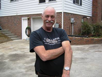
Mr. Julian Morrison Master Machinist & Metal-cutting Mentor
|
Mr. Don Niday Model Railroader, Craftsman & Artist
|
Dr. Jeff Nichols, PhD IT Whiz & Computer Guru (and one of the world's great eaters)
|
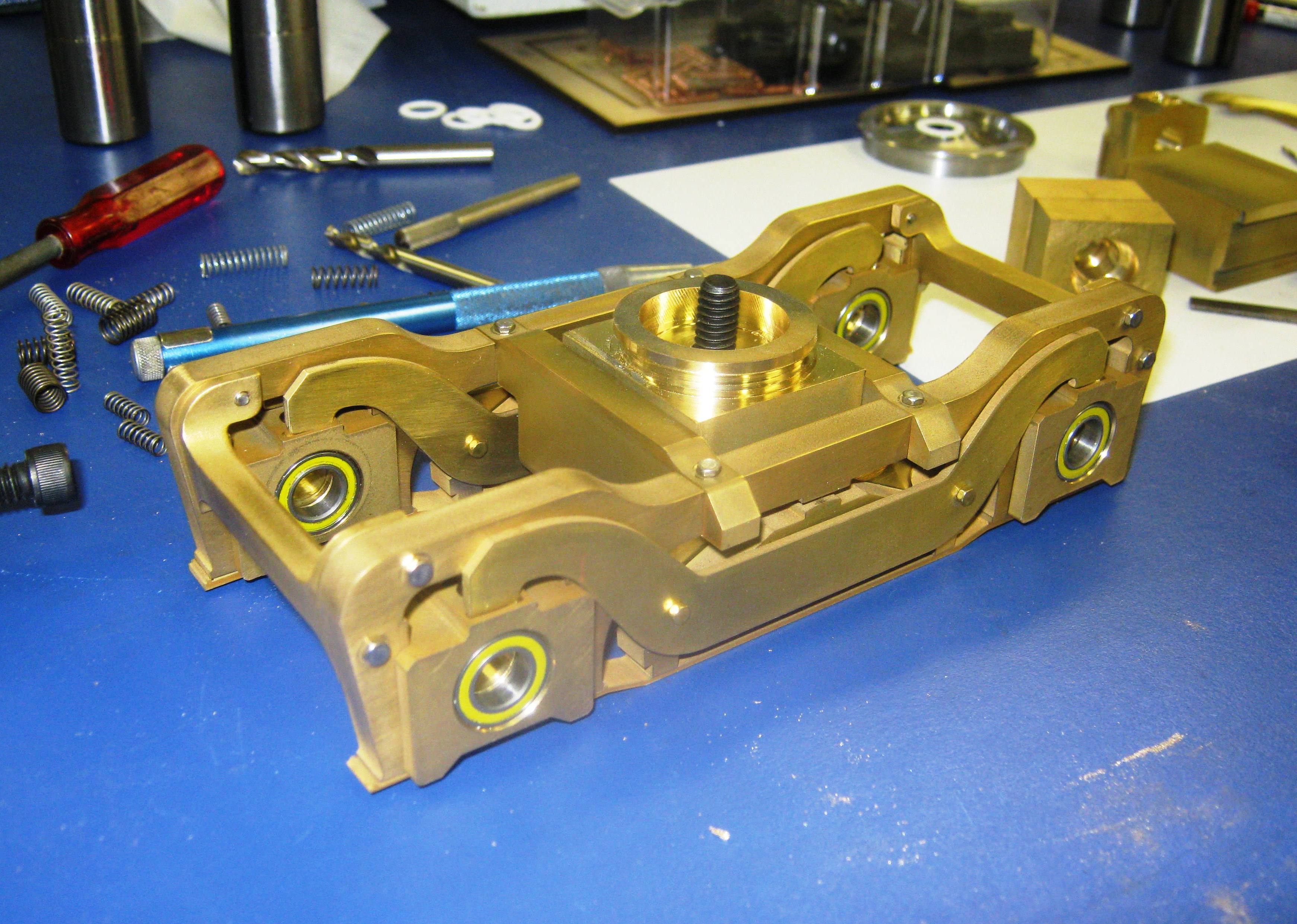
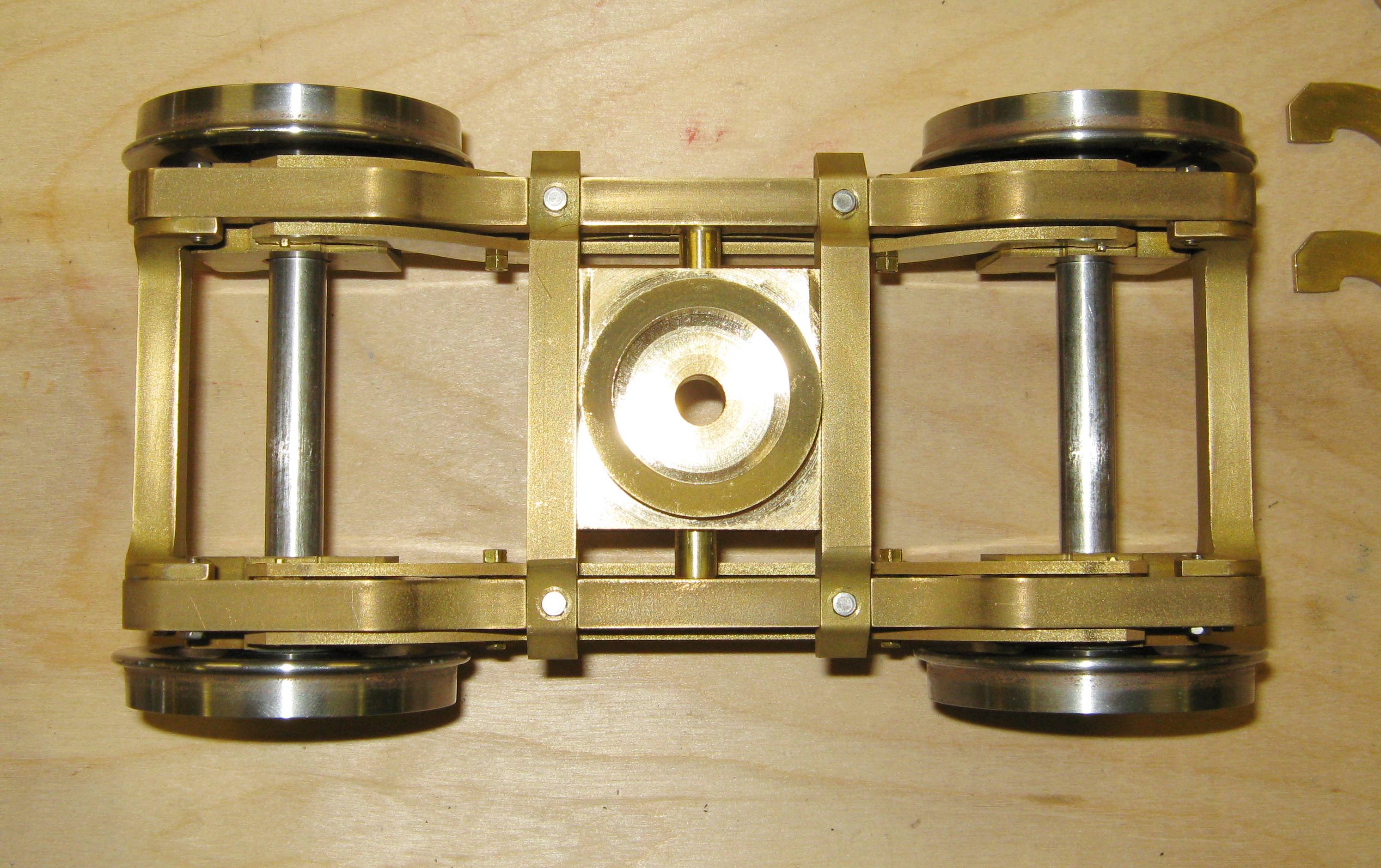
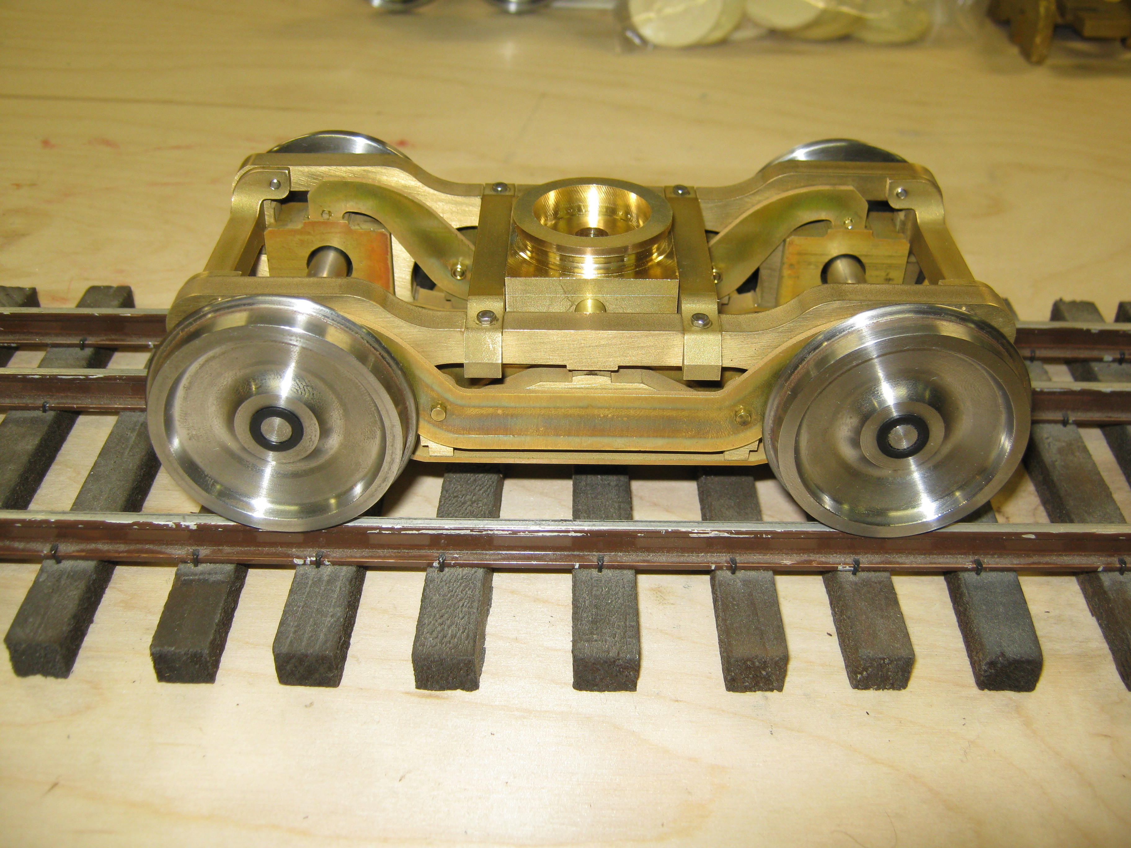
.jpg) .jpg) 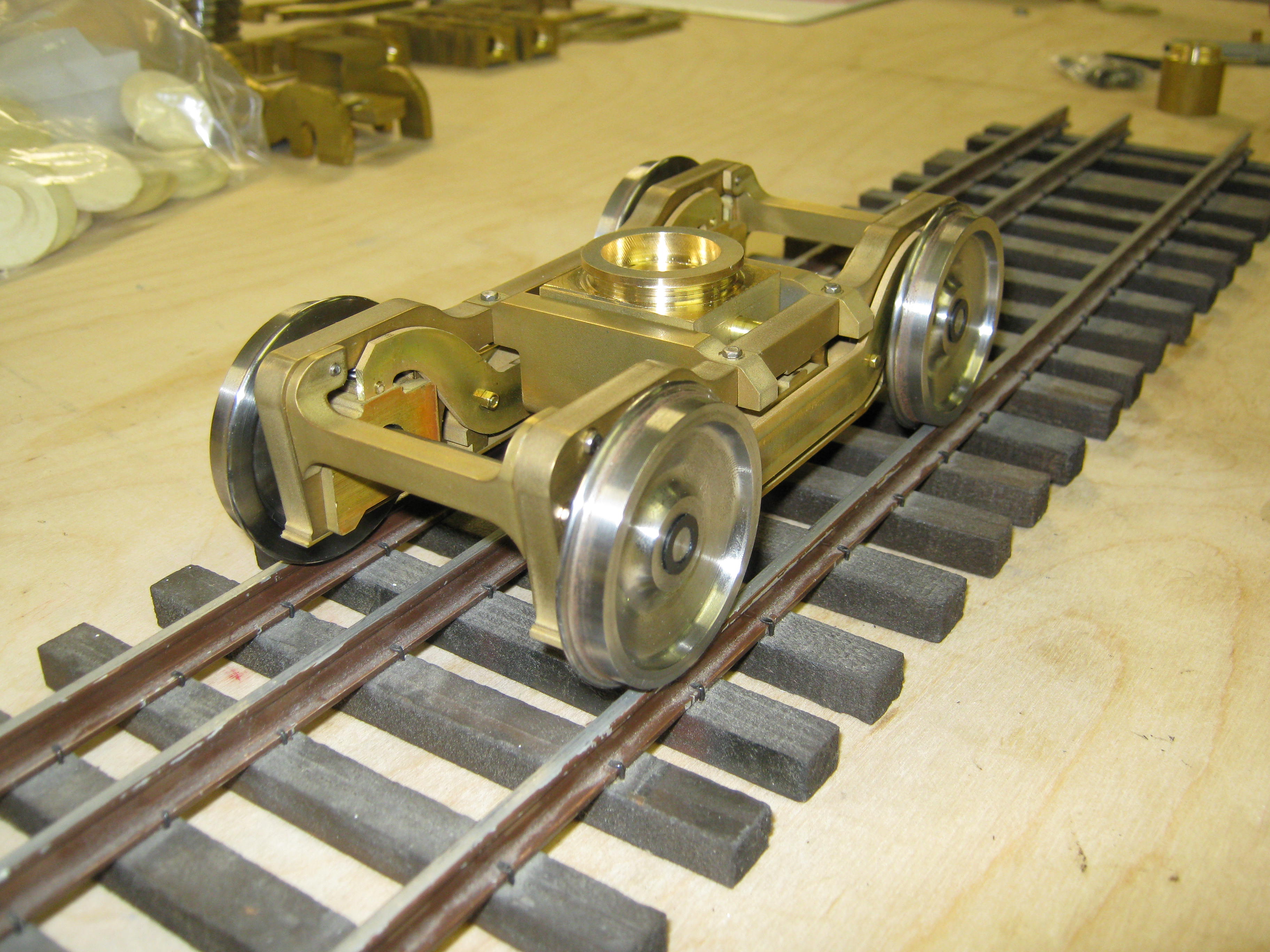 L-105
Lead Truck Completed
(updated 2-22-11) L-105
Lead Truck Completed
(updated 2-22-11)
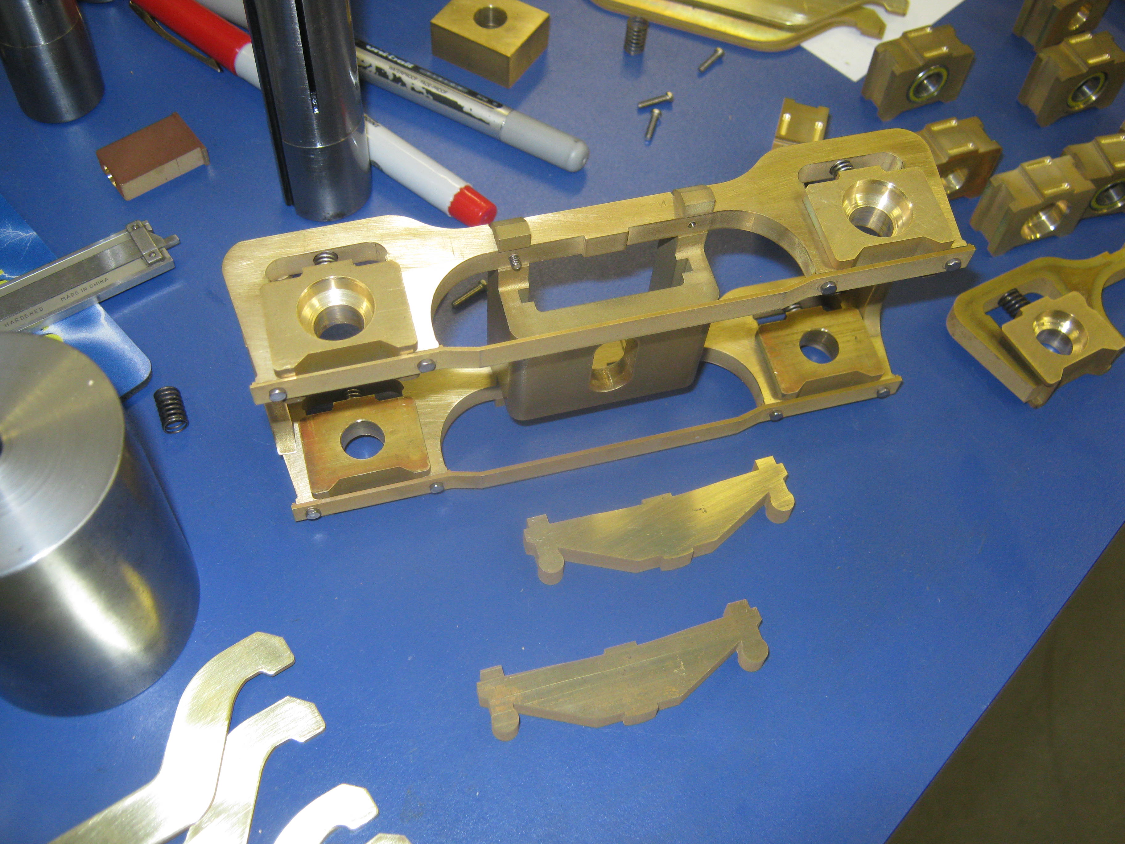
The first order of business in my work on the D&RGW L-105 project has been to complete the Baldwin designed lead truck. This same lead truck was, like the trailing truck and tender, also used on the M-68 4-8-4, the two classes of locomotive being purpose built by Baldwin to have many interchangeable parts. Since I did not have part drawings of the L-105 lead truck--only the elevation and section drawings--about 25 hours of CAD work were required to trace and guesstimate the truck's design. 115 man-hours of machining and assembly work later, the first truck was finished by me (Dave) in mid-January. This is only the second 4-wheel lead truck that I have built, the first being a somewhat stiff affair I filed in 2001 from brass bits and pieces for a model of Little River Lumber Co. baby pacific #110 (inset above). By contrast, the L-105 lead truck is sprung, equalized, and features a spring-loaded centering device. Heart-shaped rockers for the centering device were deemed too fiddly for a rugged outdoor, operating model.
Most of the brass parts were cut on my Japax wire EDM with a bit of additional mill work done on a Bridgeport clone. 36" lead truck wheels were supplied by Bill Brisko of Pacific Locomotive Works. Bushings and axles were made on my Monarch 10EE turret lathe. I'm confident that if I had it to do it over again, I would make the frame and centering components as casting patterns, and then have additional copies shell cast, which would greatly amortize the cost of so much machine work. Even so, I'm pleased with the results. My thanks go to Capt. Tom Mix (USMC, Retired) and master-modelmaker Kelley Morris for their suggestions, insight and superb examples from the smaller scales. |
||
.jpg) 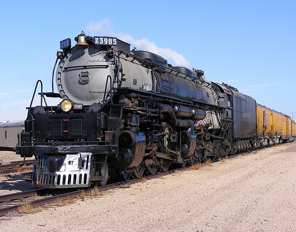 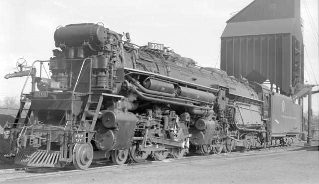 Take the Big Boy Challenge!
(updated 1-1-11) Take the Big Boy Challenge!
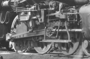
(updated 1-1-11)I was stunned when the announcement came this past Spring--Doug Hemmeter had been commissioned by Mr. Gary Bartlow to build not one but three late model UP Challengers. And then I was stunned a second time to learn that not only would three Challengers be built, but three UP Big Boy 4-8-8-4s would also be in the offing. Since then Gary and Doug have agreed that one of the Challengers will in fact be not a UP model, but the D&RGW's Baldwin-built L-105 4-6-6-4, that locomotive having shared a goodly number of parts with the D&RGW M-68 4-8-4 (compare UP 3985 with the L-105 above in B&W). These six locomotives are being built as a corroborative effort; and when complete, at least several of them will be for sale. My commission is to construct the brass and steel running gear for all six locomotives since my shop now has every machine tool a serious model builder could want (save for a CNC lathe). Barry Bogs is building the centipede tenders from styrene masters and urethane castings. Doug Hemmeter is constructing the boiler shells from brass, the cabs from styrene, and doing all the final detail and assembly work. Bill Brisko is providing the driver center castings, 36" and 42" wheels. In addition to Bill's 3D CAD and rapid prototype work on the drivers, various other complex detail parts are being created either by myself or a helper as 3D CAD drawings in Autodesk Inventor and then rapid prototyped in ABS. In the weeks to come, I will be creating a separate page for chronicling this massive project. In the meantime see Barry Bogs' work above. | ||
| Continue to CME News from 2010 . . . | ||
|
Last update: 26 August 2013
| ||
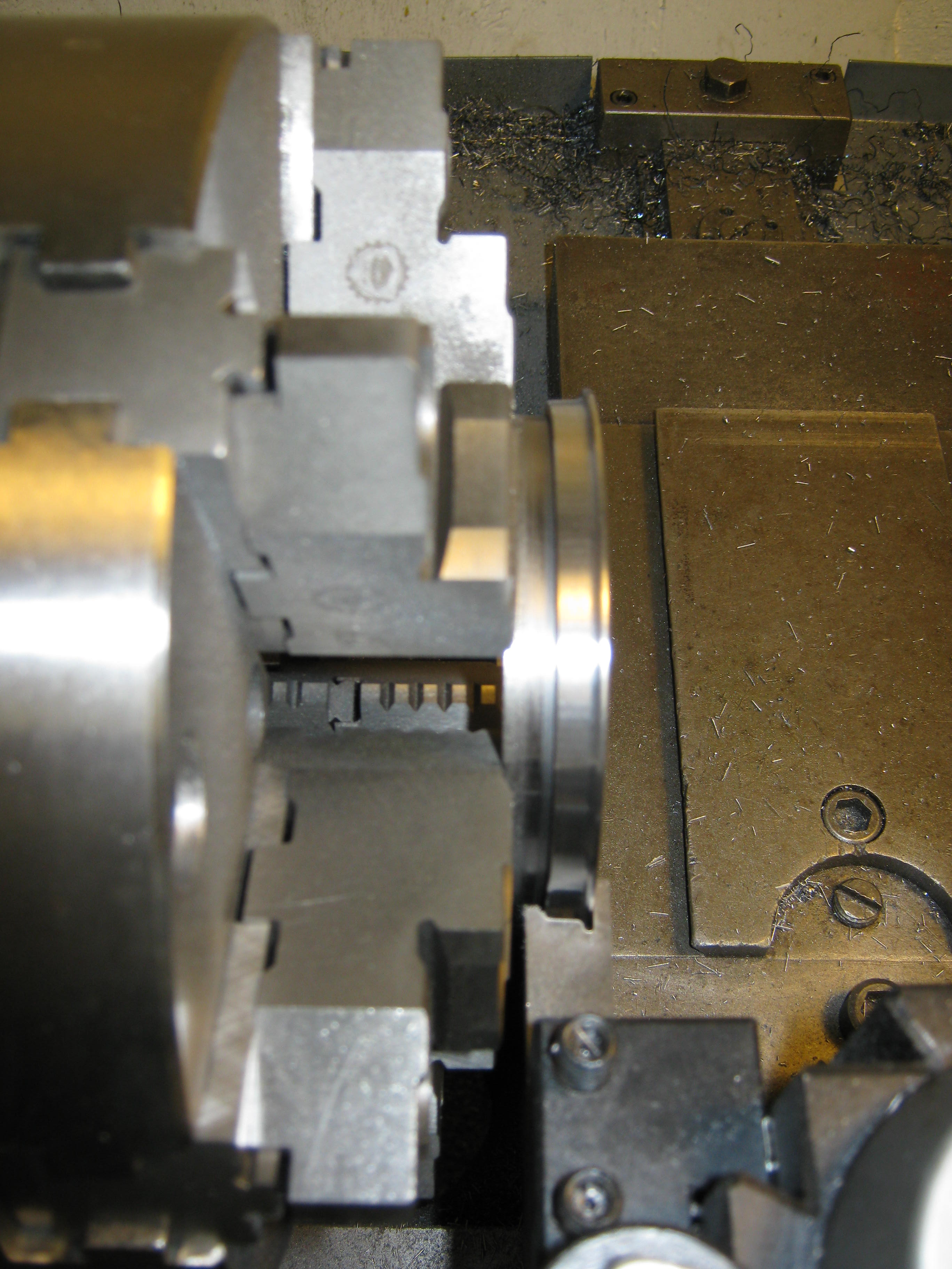
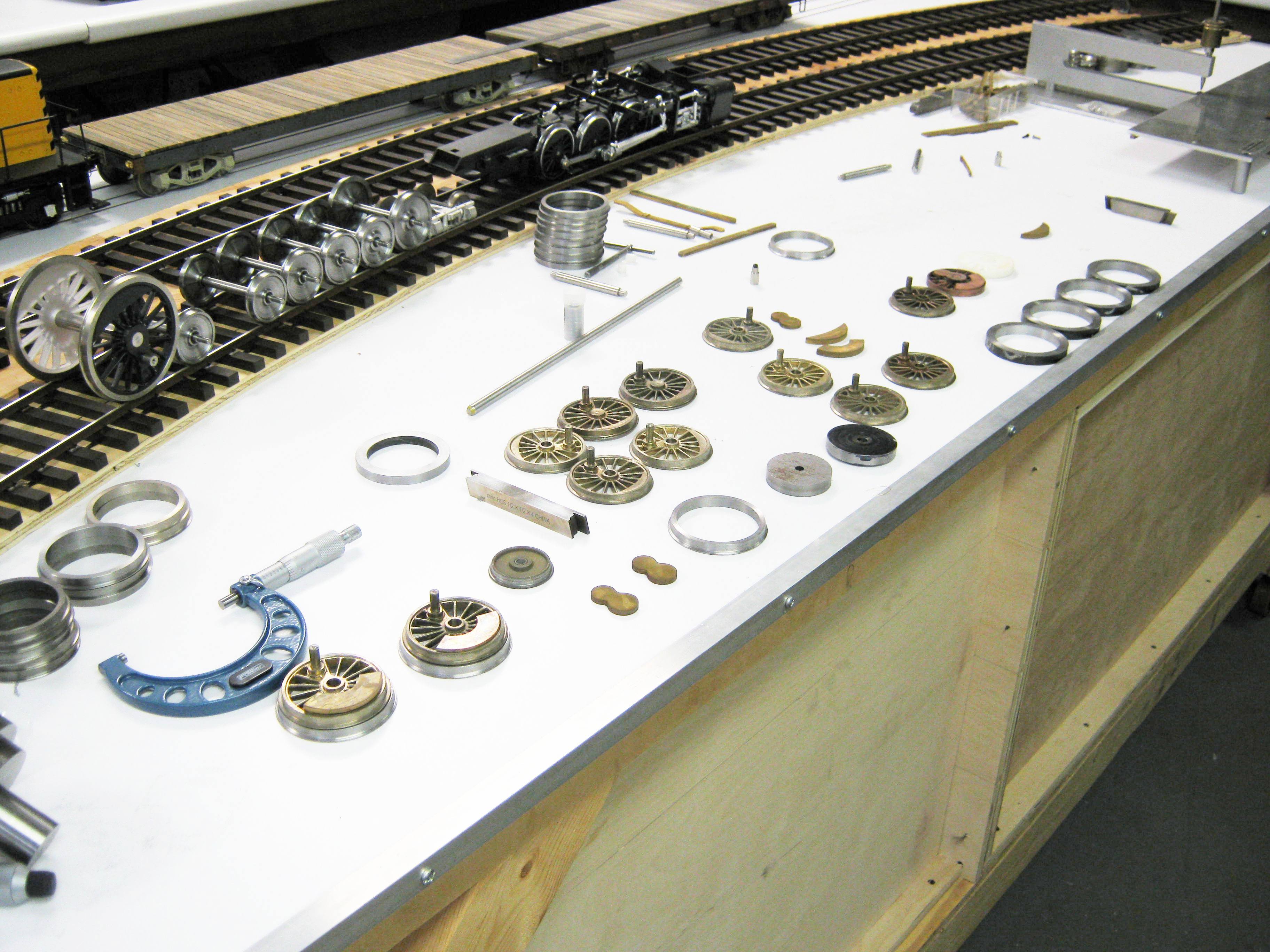
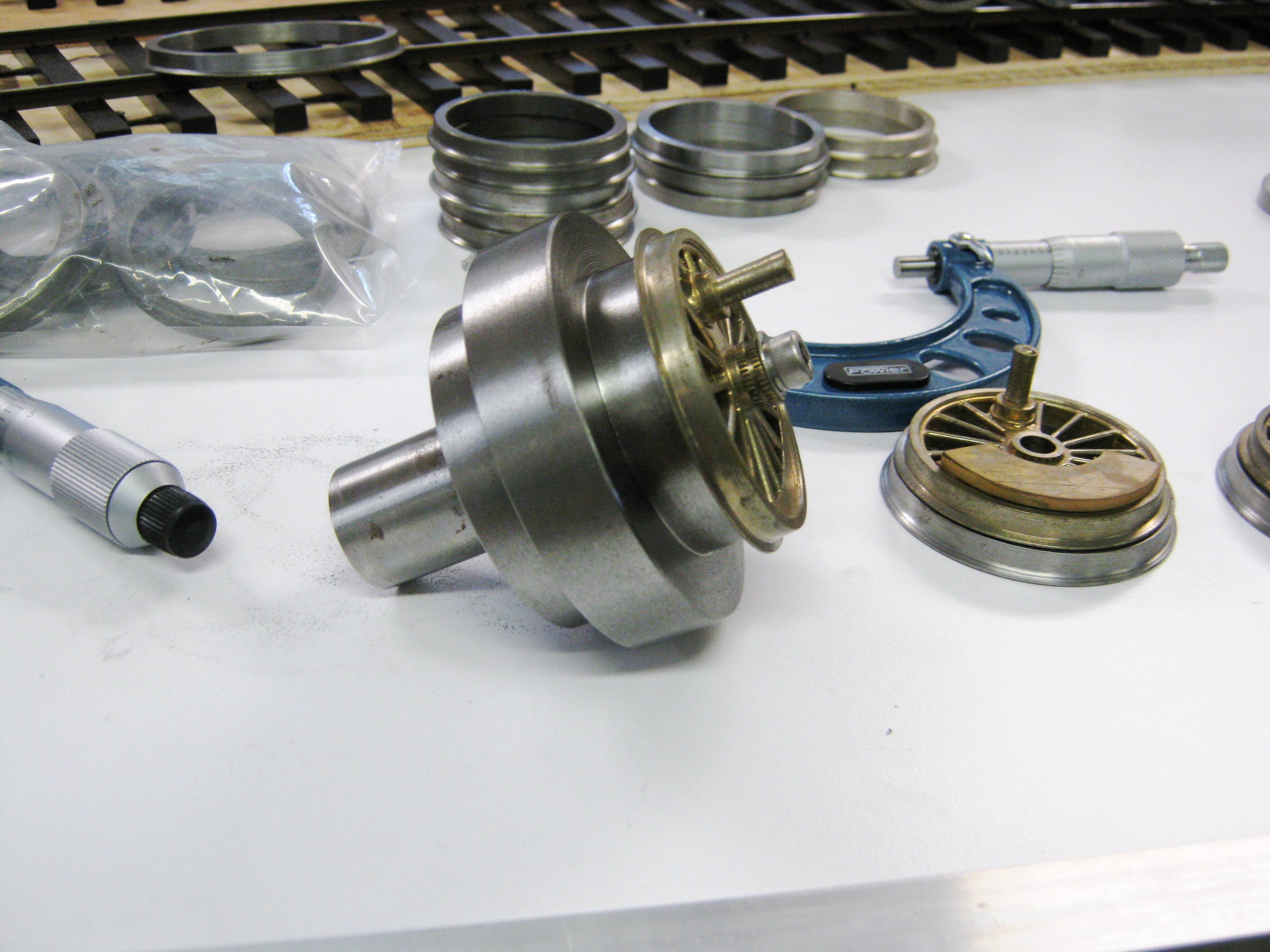
.jpg)
.jpg) •
Machining Drivers and Axles--Doug had some
leftover driver centers from the M-68 project which had been
partially machined by the late Doug Cockerham. These Baldwin
disc drivers were the original impetus to building an L-105
Challenger. These drivers were originally intended for 73" OD
tyres, but we are shaving them down to be compatible with the
L-105's 70" drivers. Tyres are made be me with a bit of
modification, namely the cutting of a new tread profile, same as
we have used on our wheelsets and for which Gary Watkins of
•
Machining Drivers and Axles--Doug had some
leftover driver centers from the M-68 project which had been
partially machined by the late Doug Cockerham. These Baldwin
disc drivers were the original impetus to building an L-105
Challenger. These drivers were originally intended for 73" OD
tyres, but we are shaving them down to be compatible with the
L-105's 70" drivers. Tyres are made be me with a bit of
modification, namely the cutting of a new tread profile, same as
we have used on our wheelsets and for which Gary Watkins of
.JPG)
.jpg)
.jpg)
.jpg)
.jpg)
.jpg)
.jpg)
.jpg)
.jpg)
.jpg)
.jpg)
.gif) •
50" Drivers for Southern Railway G-Class 2-8-0--The
Southern Railway G-Class 2-8-0 was essentially a catch-all
category for a number of pre-merger 20x24 slide valve
consolidations inherited by the Southern from predecessor roads.
One has been restored to operation just this past year (2010):
•
50" Drivers for Southern Railway G-Class 2-8-0--The
Southern Railway G-Class 2-8-0 was essentially a catch-all
category for a number of pre-merger 20x24 slide valve
consolidations inherited by the Southern from predecessor roads.
One has been restored to operation just this past year (2010):
.JPG)
 which my friend Barry Bogs was initially going to
use on his Denver & Salt Lake 2-6-6-0 in Gauge 3. But Bill
Zingheim deserves credit for the first foray down this road.
Bill is a model railroader and micro-manufacturer, serving the
live steam phase of the hobby with
which my friend Barry Bogs was initially going to
use on his Denver & Salt Lake 2-6-6-0 in Gauge 3. But Bill
Zingheim deserves credit for the first foray down this road.
Bill is a model railroader and micro-manufacturer, serving the
live steam phase of the hobby with
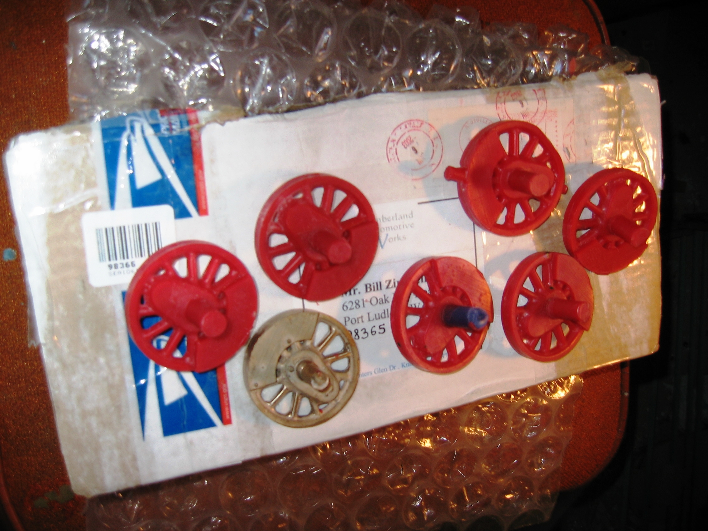
.jpg.jpg) •
44" Drivers for Baldwin Logging 2-6-2--In
the late 1990s a man by the name of Ed Silveira from Thousand
Oaks, California began marketing a line of die cast replacement
drivers under the name of Palacina Productions. They were meant
to aid kitbashers and scratch builders who were then modifying
Bachman Big Hauler 4-6-0s as well as Aristo-Craft pacific mechanisms. I
would up with several dozen in an assortment of sizes (2", 2Ľ"
and 2˝" OD). A number of the 2Ľ"
drivers found there way onto Gauge 3 2-4-4-2 mechanisms,
replacing the LGB Stainz drivers of their respective motor
blocks. The remaining six I am now using on a customer project.
Mr. Aaron Rohyans, who hails from Indiana, is the newest convert
to 1:20.3 standard gauge, and he wants to build a model of White
Water Valley (formerly Alger-Sullivan Lumber Co., formerly
Florala Saw Mill) 2-6-2 #100. Aaron has asked me to create a
chassis for both the tender and the locomotive. He will do the
rest. So the last of the Palacina drivers has now found a home, but
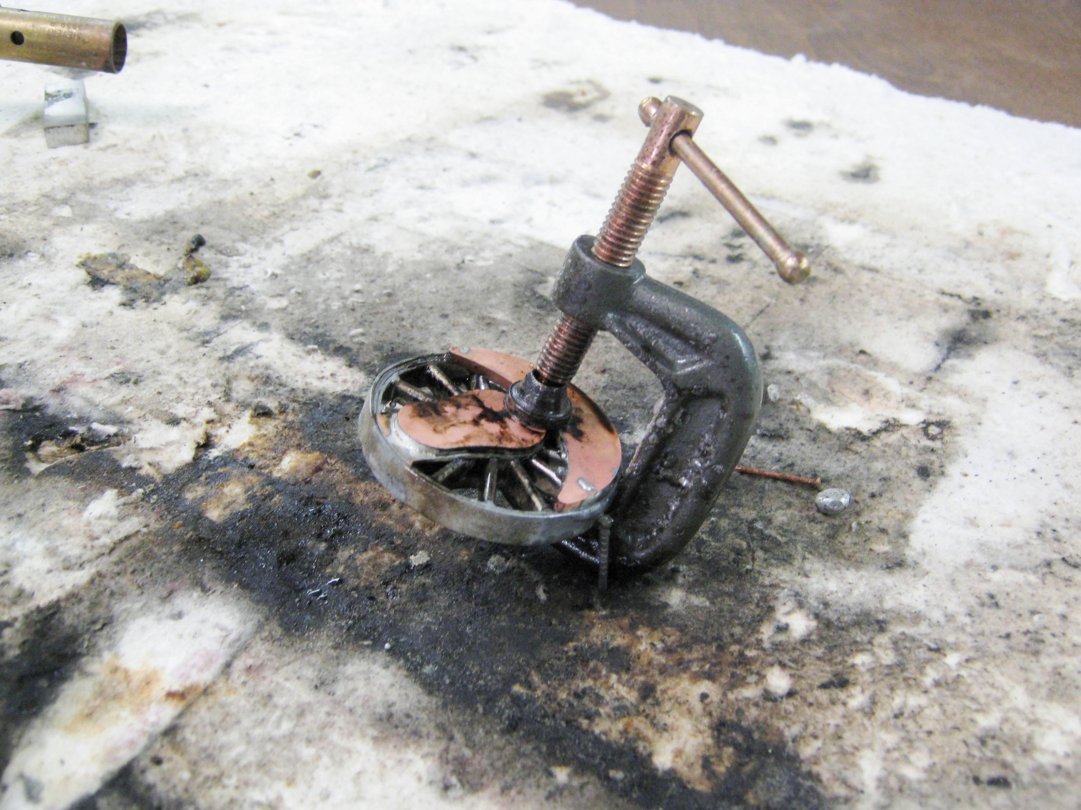
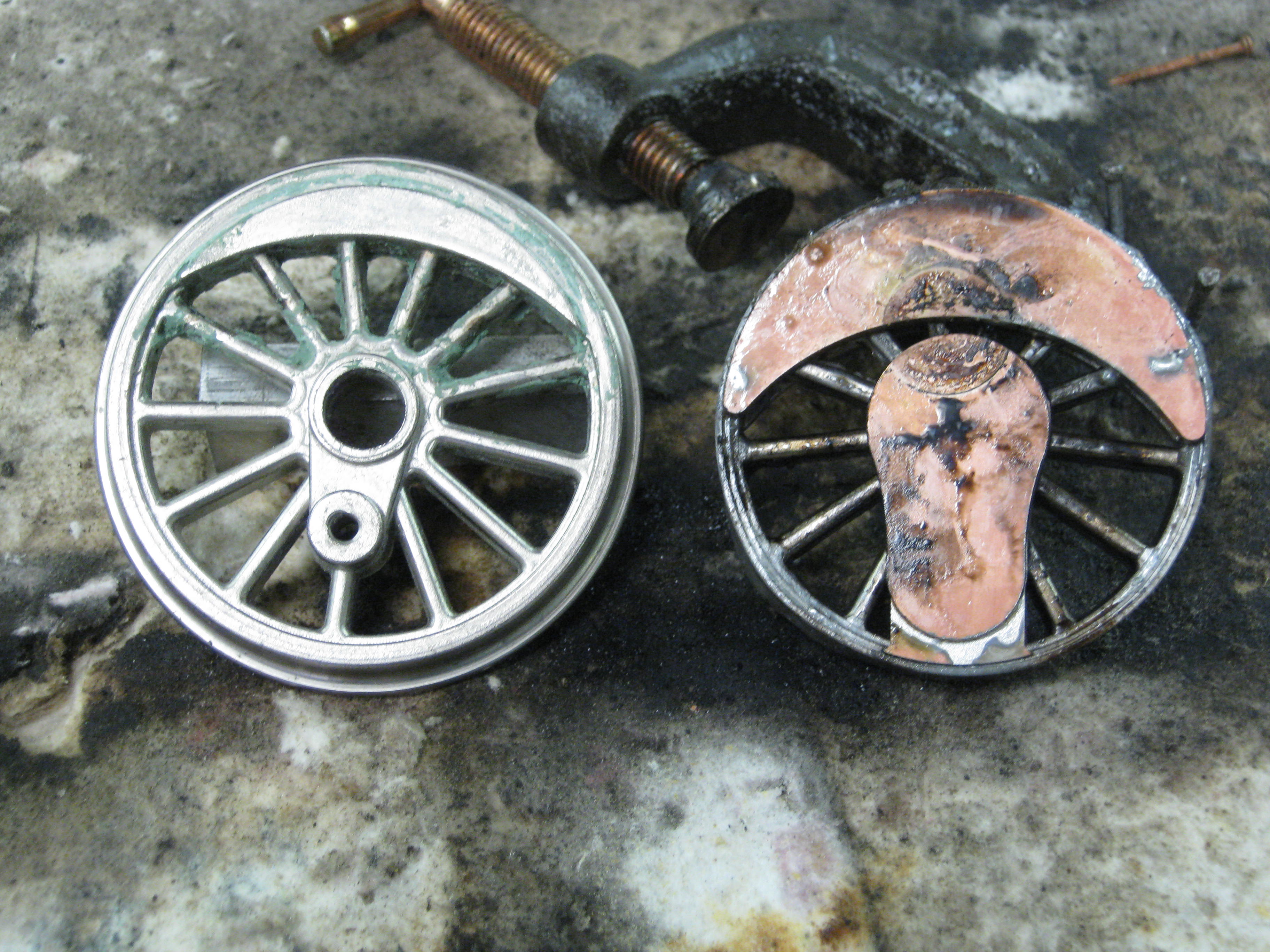
only with extensive modifications. These include turning off the
old counterweights and crankpin hub, the addition of new brass
ones which are soldered on, and the application of separate 44"
steel tyres with mylar insulation between driver center and tyre.
For anyone else trying to modify die cast drivers, one word of
caution: Die cast alloys readily melt under the heat of a
propane torch! Use caution. Palacina originals are pictured are
far left with additional wire EDM cut brass shims at middle,
followed by pics of my special arbor for holding the drivers and
then a few pics of the soldered driver center.
•
44" Drivers for Baldwin Logging 2-6-2--In
the late 1990s a man by the name of Ed Silveira from Thousand
Oaks, California began marketing a line of die cast replacement
drivers under the name of Palacina Productions. They were meant
to aid kitbashers and scratch builders who were then modifying
Bachman Big Hauler 4-6-0s as well as Aristo-Craft pacific mechanisms. I
would up with several dozen in an assortment of sizes (2", 2Ľ"
and 2˝" OD). A number of the 2Ľ"
drivers found there way onto Gauge 3 2-4-4-2 mechanisms,
replacing the LGB Stainz drivers of their respective motor
blocks. The remaining six I am now using on a customer project.
Mr. Aaron Rohyans, who hails from Indiana, is the newest convert
to 1:20.3 standard gauge, and he wants to build a model of White
Water Valley (formerly Alger-Sullivan Lumber Co., formerly
Florala Saw Mill) 2-6-2 #100. Aaron has asked me to create a
chassis for both the tender and the locomotive. He will do the
rest. So the last of the Palacina drivers has now found a home, but
only with extensive modifications. These include turning off the
old counterweights and crankpin hub, the addition of new brass
ones which are soldered on, and the application of separate 44"
steel tyres with mylar insulation between driver center and tyre.
For anyone else trying to modify die cast drivers, one word of
caution: Die cast alloys readily melt under the heat of a
propane torch! Use caution. Palacina originals are pictured are
far left with additional wire EDM cut brass shims at middle,
followed by pics of my special arbor for holding the drivers and
then a few pics of the soldered driver center.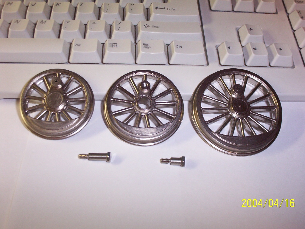
.jpg)
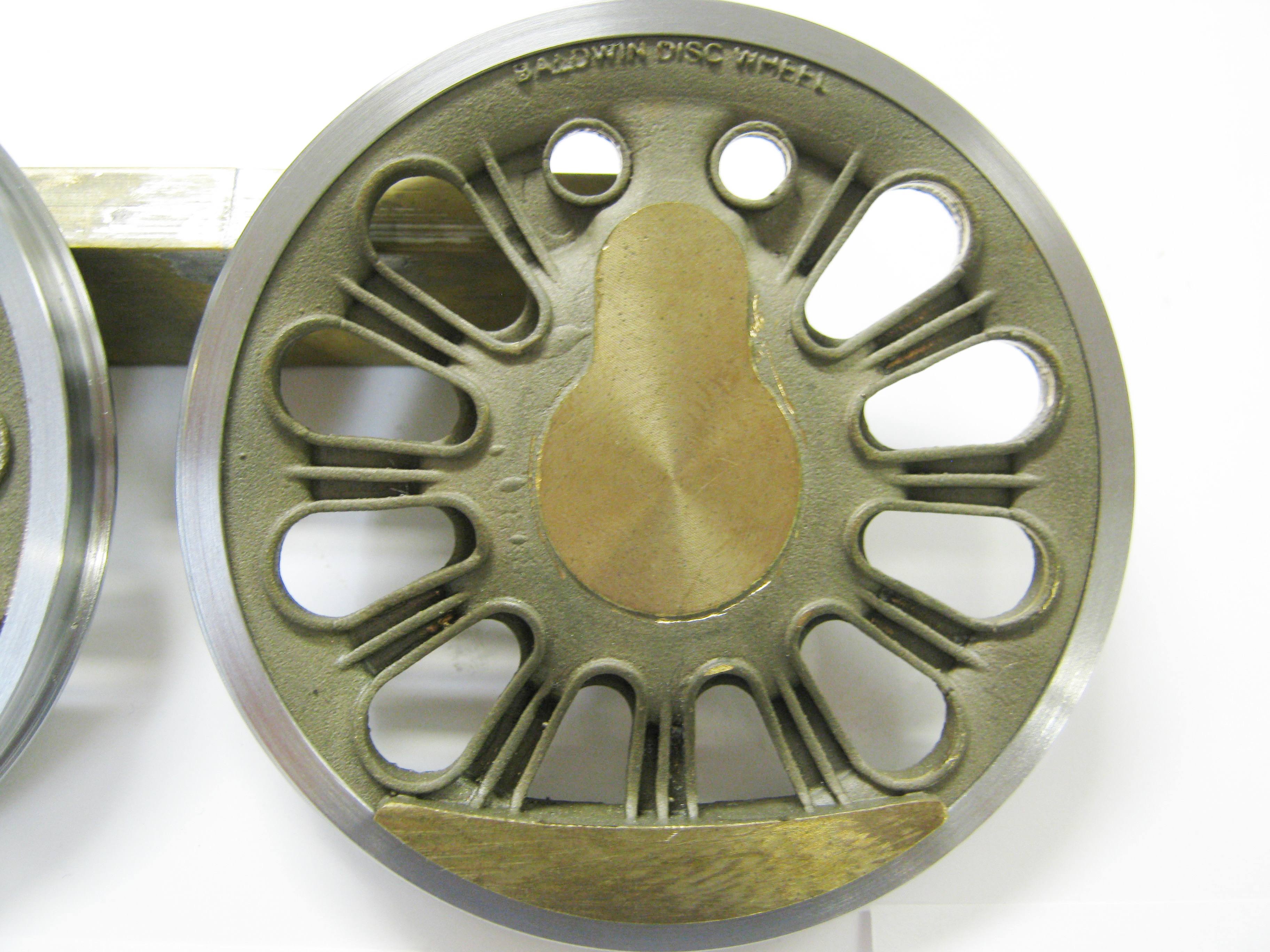
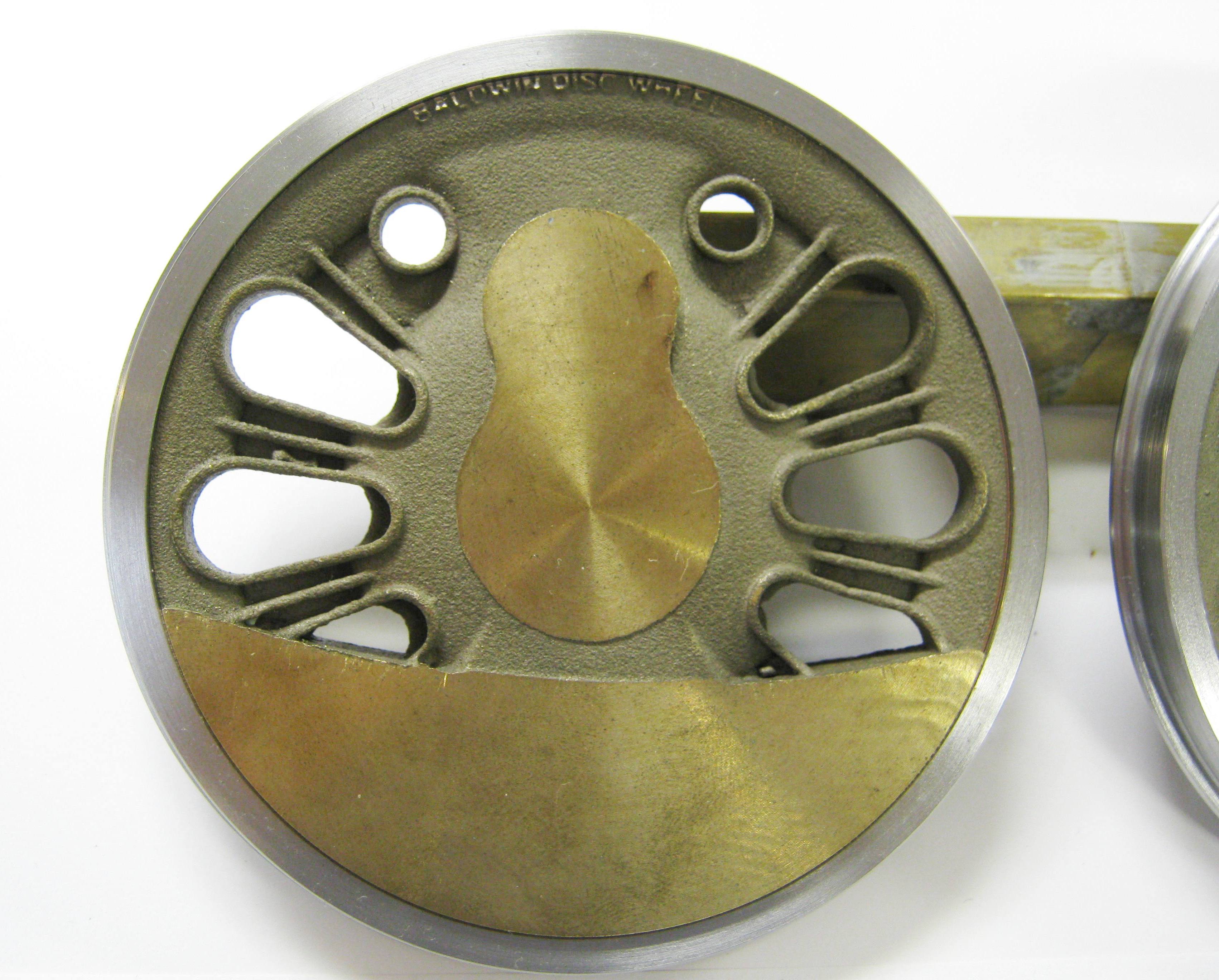
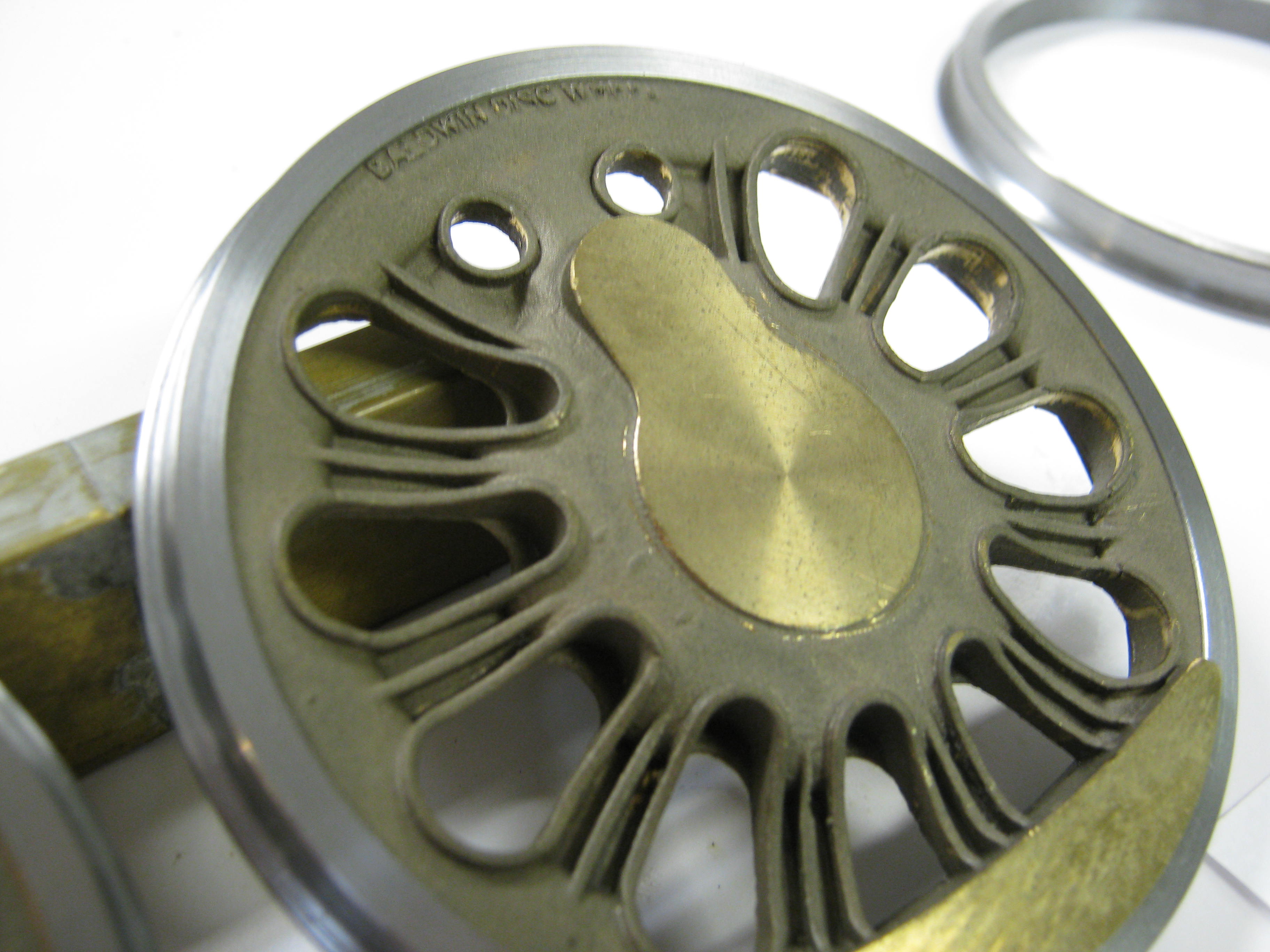
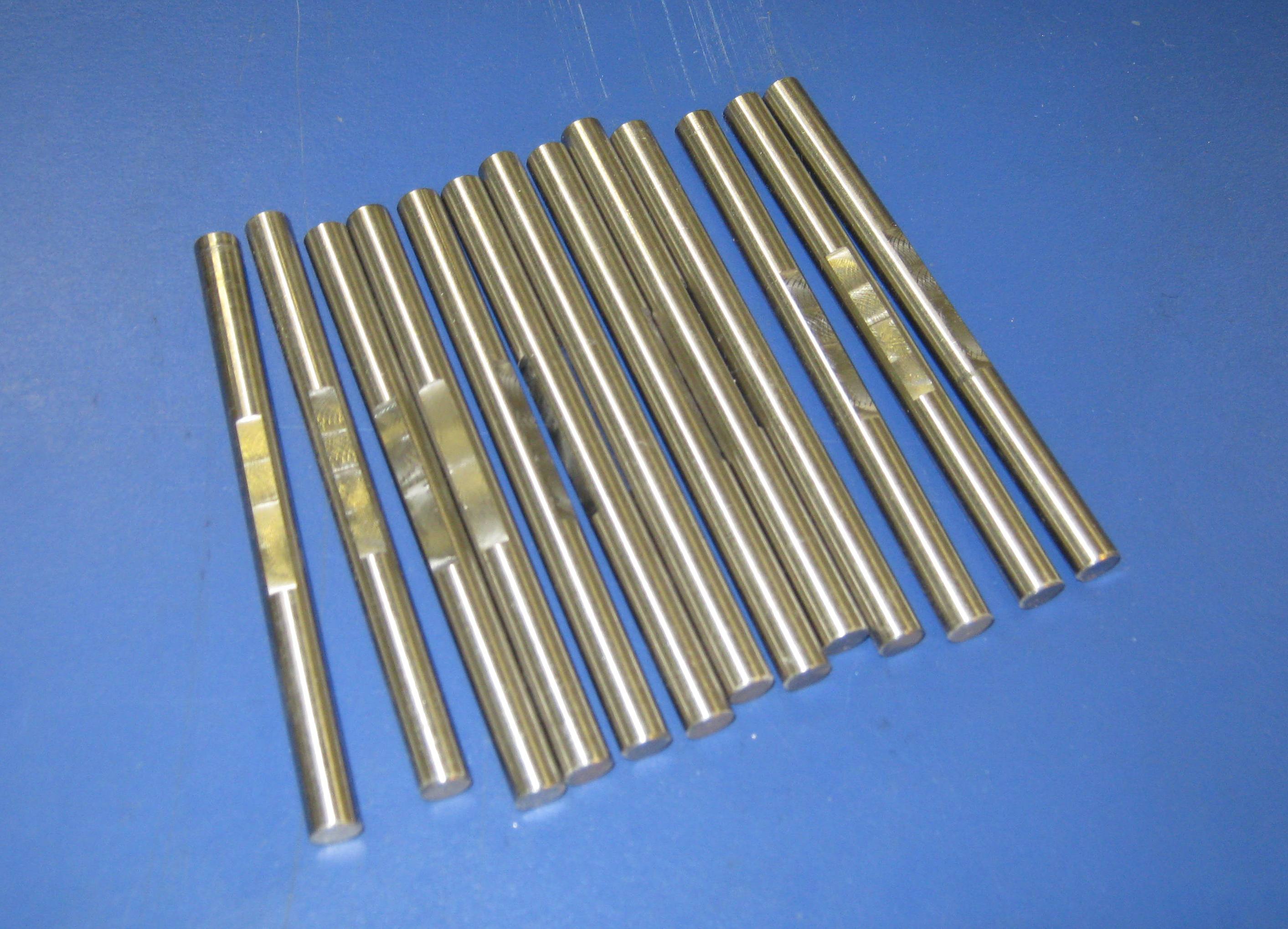
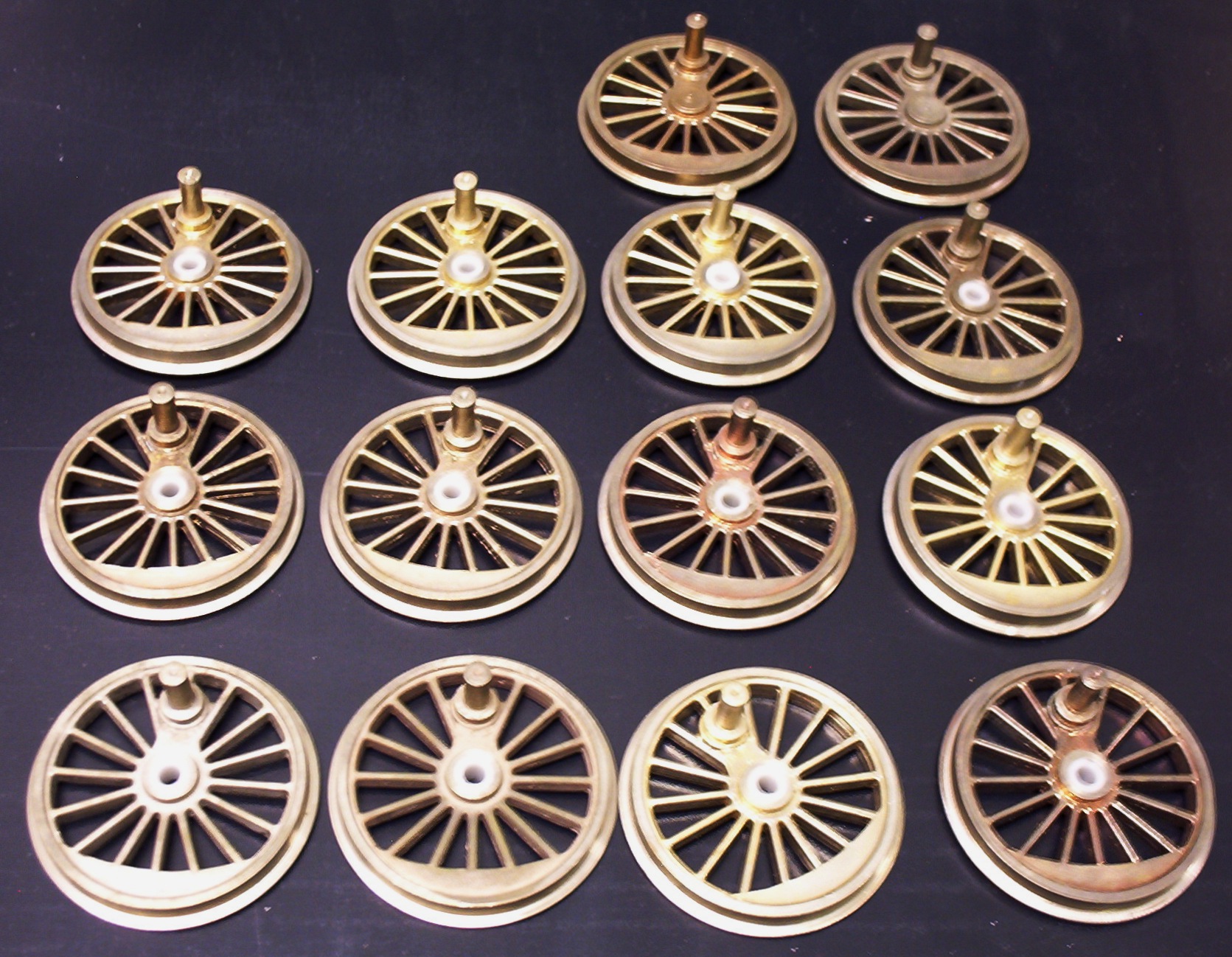
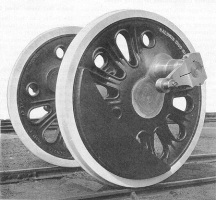 •
70" Drivers for D&RGW L-105 4-6-6-4--Following
the completion of the chassis for his four (yes, that's right--four!)
D&RGW M-68 4-8-4s, Doug Hemmeter had 13 driver castings
left over, enough for one D&RGW L-105 4-6-6-4 plus a spare. The
M-68 and the L-105 were built at about the same time by Baldwin
and shared a number of interchangeable components. Their drivers
were nearly so, the M-68 using a 73" version of the unique
Baldwin disc design whereas the L-105 had a 70" version. Some of
Doug's drivers were partially machined by the late Doug
Cockerham. I am now completing the job with my own 70" steel
tyres, crankpins, 8mm axles, and quartering jigs. More pics to
follow.
•
70" Drivers for D&RGW L-105 4-6-6-4--Following
the completion of the chassis for his four (yes, that's right--four!)
D&RGW M-68 4-8-4s, Doug Hemmeter had 13 driver castings
left over, enough for one D&RGW L-105 4-6-6-4 plus a spare. The
M-68 and the L-105 were built at about the same time by Baldwin
and shared a number of interchangeable components. Their drivers
were nearly so, the M-68 using a 73" version of the unique
Baldwin disc design whereas the L-105 had a 70" version. Some of
Doug's drivers were partially machined by the late Doug
Cockerham. I am now completing the job with my own 70" steel
tyres, crankpins, 8mm axles, and quartering jigs. More pics to
follow.%20003.jpg)
%20007.jpg)
%20014.jpg)
%20002.jpg)
%20006.jpg)
%20003.jpg)
%20013.jpg)
.jpg)
.jpg)
.jpg)
%20035.jpg)
%20034.jpg)
%20038.jpg)
%20039.jpg)
%20051.jpg)

.jpg)
.jpg)