.JPG)
"Your source for standard gauge modeling in 1:20.3"
|
|
|
"Your source for standard gauge modeling in 1:20.3" |
|
|
.jpg) |
Doug Hemmeter (at left with his wife Mary) is a marine engineer hailing from the Houston area; and over the last several years he has begun to distinguish himself as first a kitbasher of Fn3 locomotives--most notably with a series of D&RGW C-25s based upon the Bachman 2-8-0 drive, built with an all new boiler, cab and tender--and now as a scratchbuilder of standard gauge locomotives in F scale. His series of D&RGW M-68 4-8-4s are his first foray into standard gauge. As of November 2011 he has completed two standard gauge 4-8-4s with two more close behind. What comes next: The D&RGW L-105 Challenger, big UP steam, and a C&O 2-10-4. Doug may be contacted at whemmeter@sbcglobal.net and at wdh_marine@sbcglobal.net |
.jpg) |
|
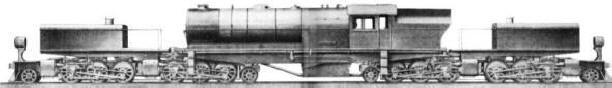
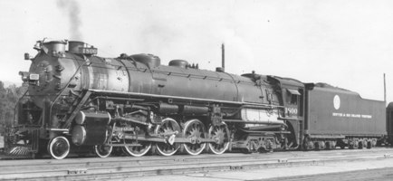
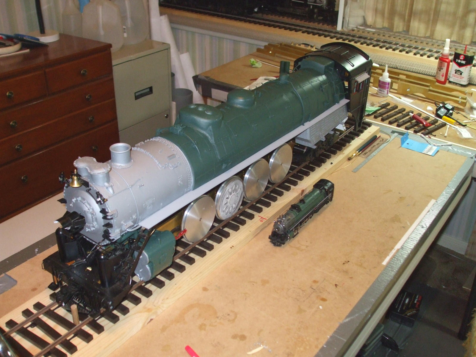
Doug's locomotive is not only the first F scale 4-8-4 to be built, but it is also the first F scale two-rail electric, standard gauge steam locomotive to be built of any sort in 1:20.3 (my baby 4-6-2 is in third place, with George Konrad's D&SL 2-6-6-0 mallet in second). But Doug is not just building one 4-8-4: He has four of the same class under construction! And yes, three of them are for sale. Elevation and section drawings for this project came from Kalmbach Publishing's Model Railroader Cyclopedia--Volume I: Steam Locomotives, whereas drawings of the distinctive Baldwin disc drivers were found in a late 1930s era Locomotive Cyclopedia. Additional help has come from an brass HO scale model of an M-68 imported by Overland Models. Additional prototype drawings of the M-68 may exist, most likely at the Denver Public Library, but as of 2008, none had been located.
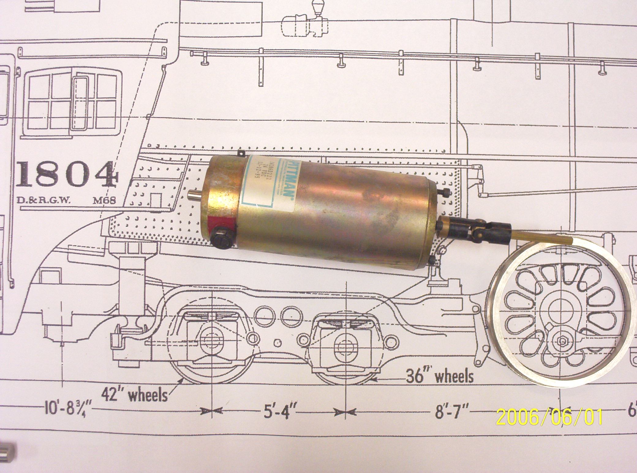
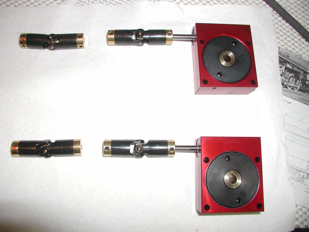
With A Little Help From My Friends Having friends to help on a project as complex a 1:20.3 scale standard gauge 4-8-4 makes all the difference in getting off the ground. In the first place, Doug has had the singular good fortune of a patron, Mr. Gary Bartlow, who commissioned the building of all four M-68 models. The late Doug Cockerham, another Texan who was well-known in the world of 2-rail O scale for repowering imported brass locomotives, machined and assembled the drivers as well as milled the main frames and various other bits of running gear for the latter three locomotives. And speaking of drivers, Mr. Bill Brisko of Pacific Locomotive Works provided the rapid prototype wax patterns for the M-68's Baldwin disc drivers based upon his own SolidWorks 3D CAD drawings (for about $2700 if you're interested in that side of the equation). Bill is also responsible for producing 3D CAD drawings of the valve gear, side and main rods. Rino Mechanical Components provided the custom built worm gearboxes (for about $337 a pop). A Pittman 14000 series DC motor powers each locomotive. 73" steel driver tires came from me. Tender, lead and trailing truck wheelsets were from my original stock, now sold by my good friend Don Niday. David Fletcher, a large scale modeler--in Melbourne, Australia--did the initial 2D CAD work for the main frames. Additional help has come from a consortium of modelers residing in the Houston area: (1) James Engle custom made the D&RGW decals,(2) Ward Hammond laser cut the production cab and tender sides from styrene (along with styrene casting patterns for the rods, valve gear, & Commonwealth tender truck side frames), (3) Barry Bogs is doing the battery, Airwire and sound installation, and (4) Jim Srenaski (famous for at one time cornering the market on all available Bachman GE 45 tonners) built the model's carrying cases as well as painted their cabs, pilots and air compressors. |
|
|
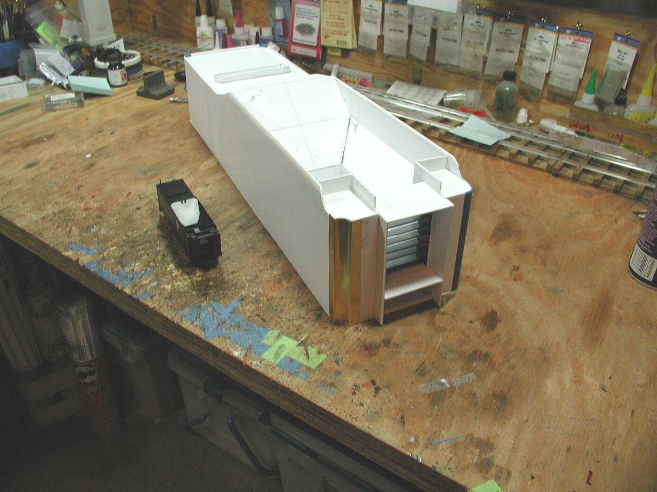
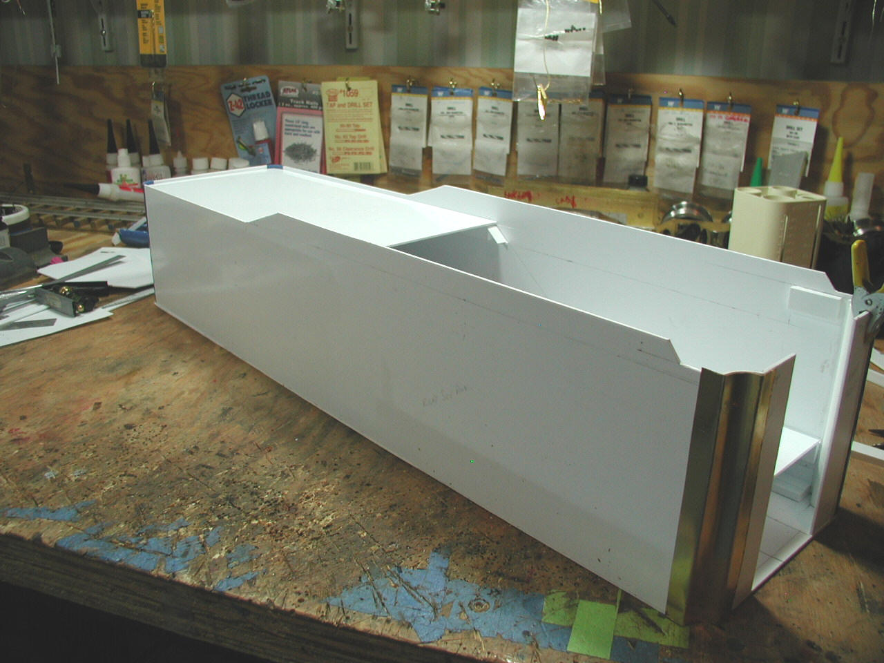
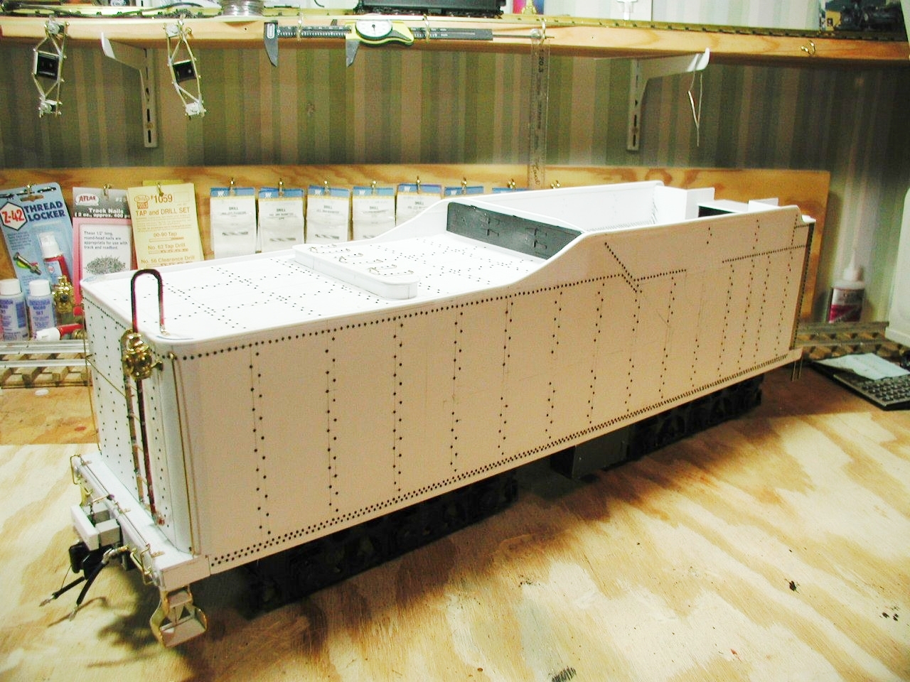
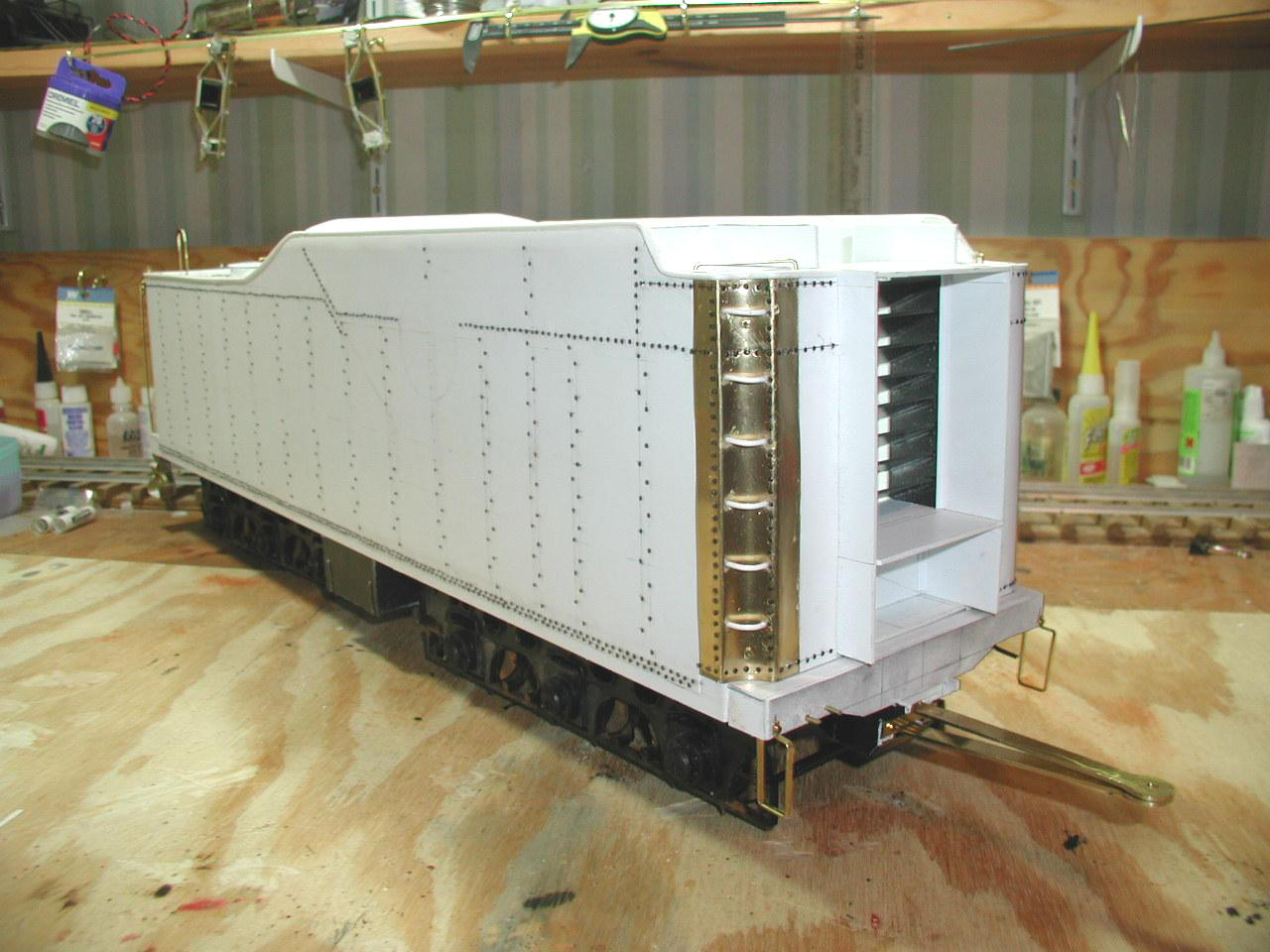
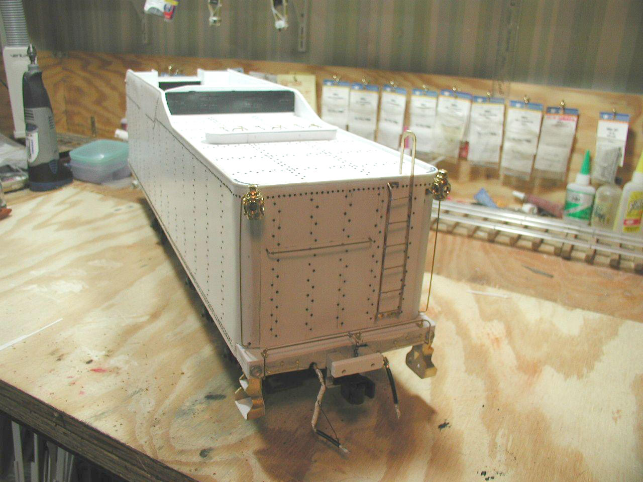
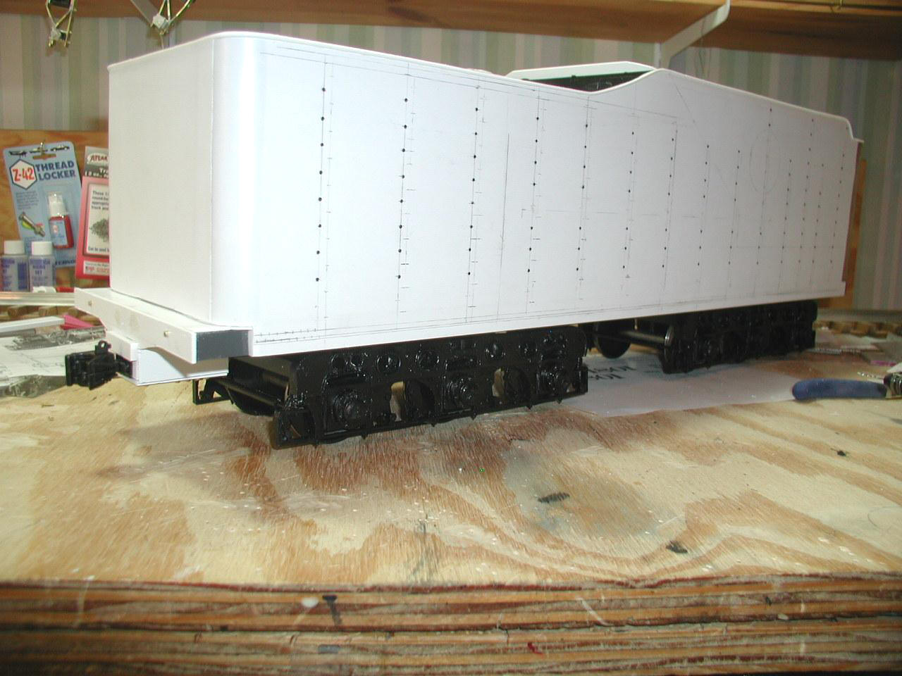
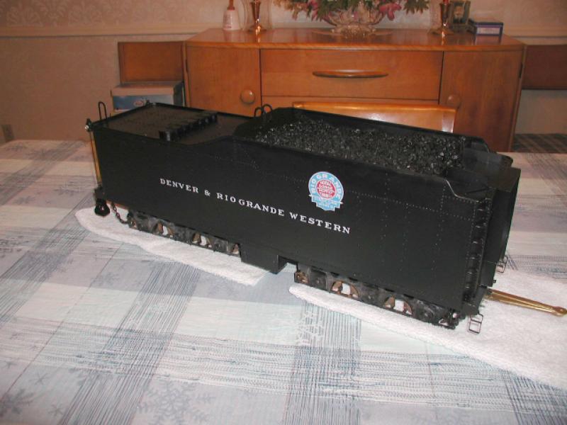
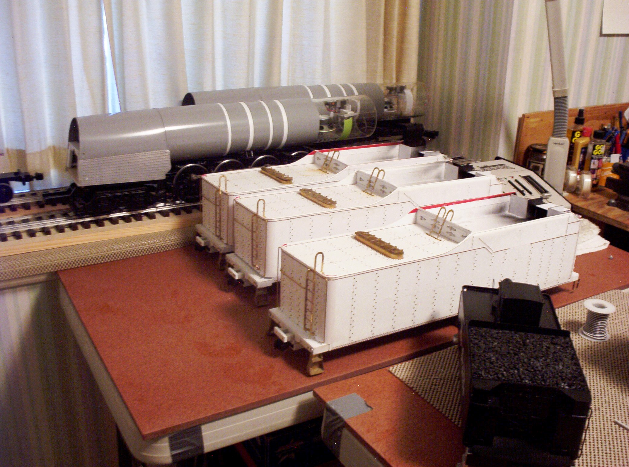
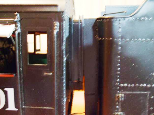
The Tender
|
|
|
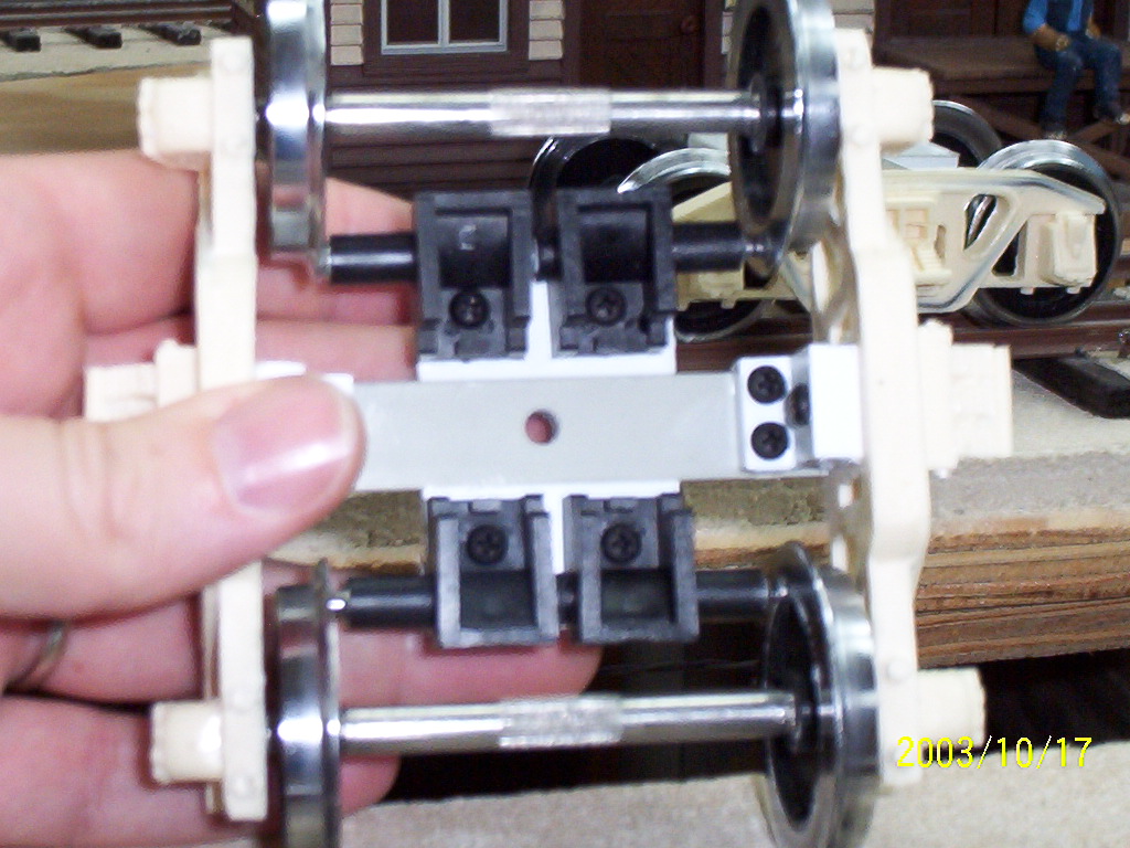
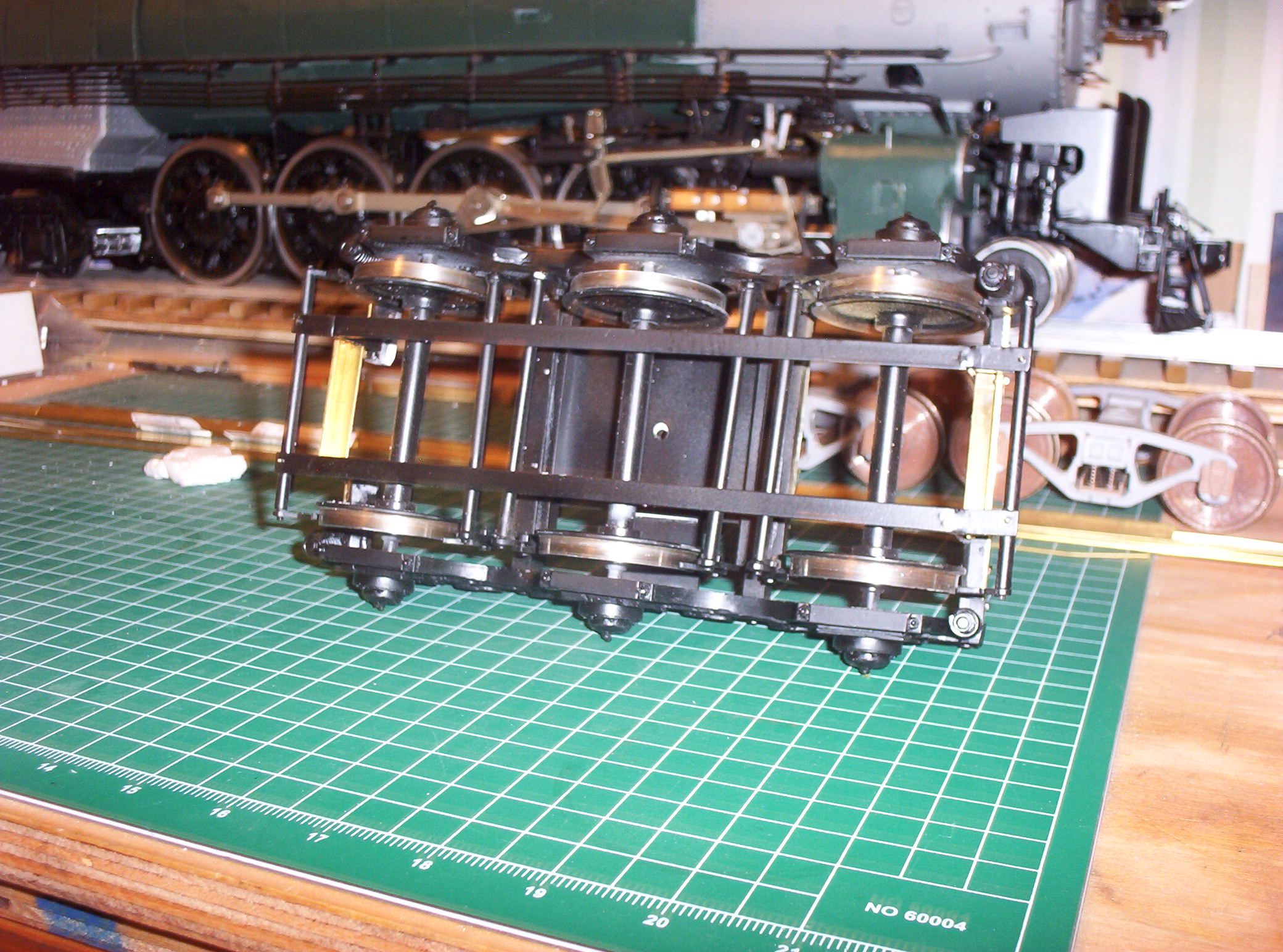
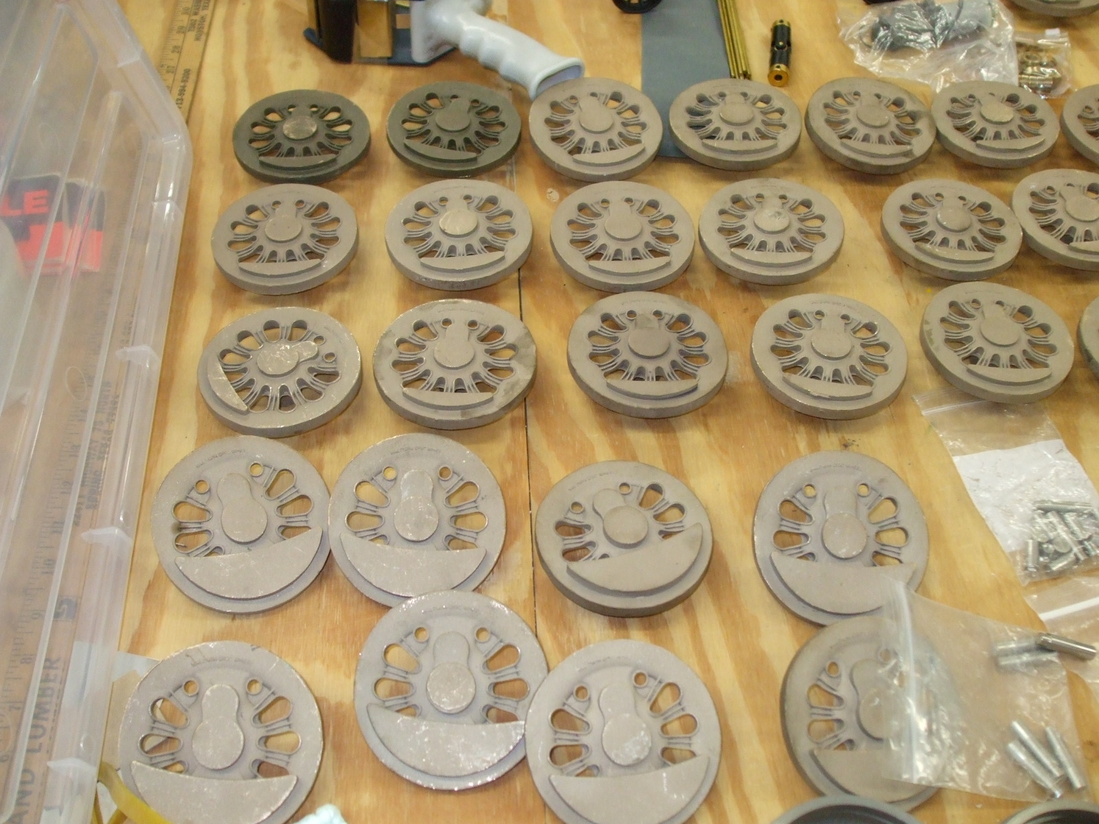
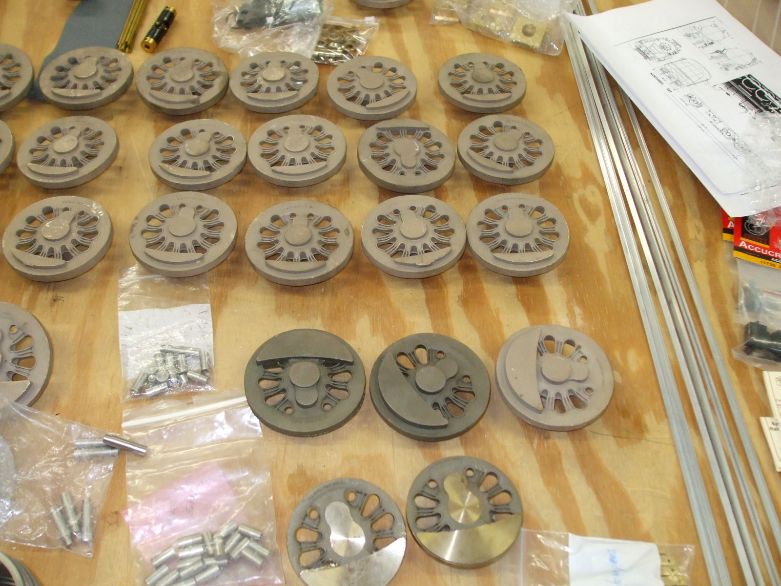
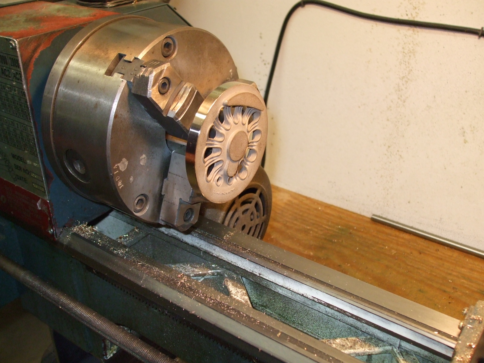
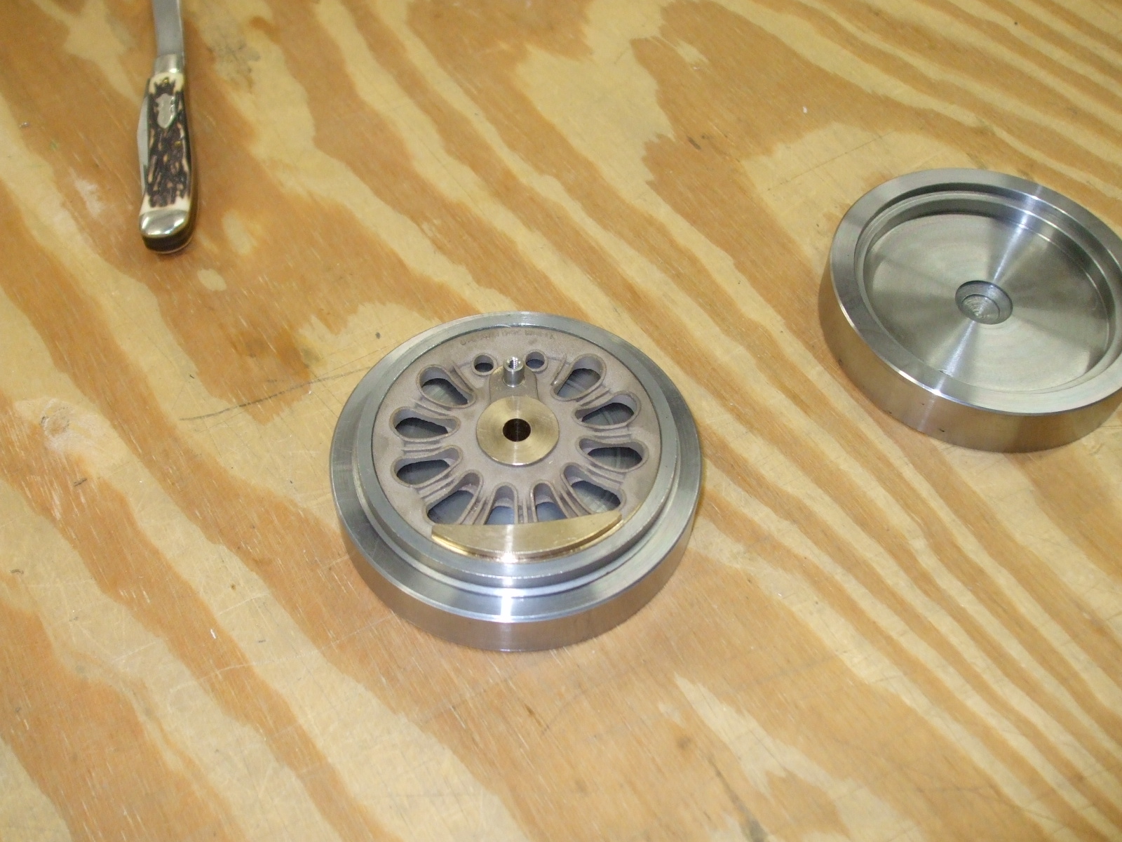
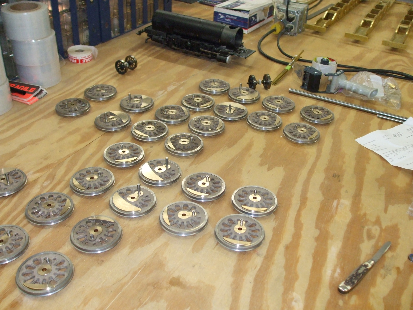
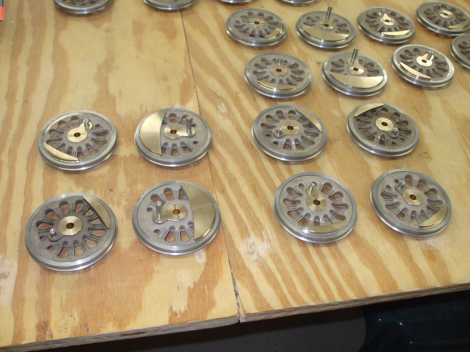
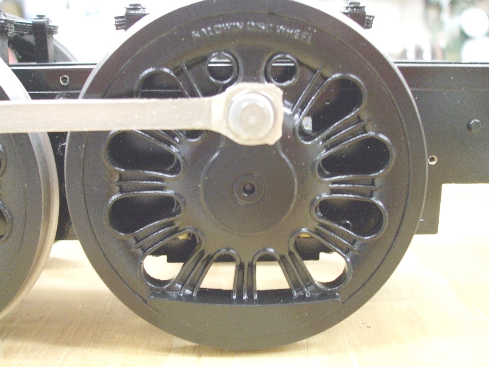
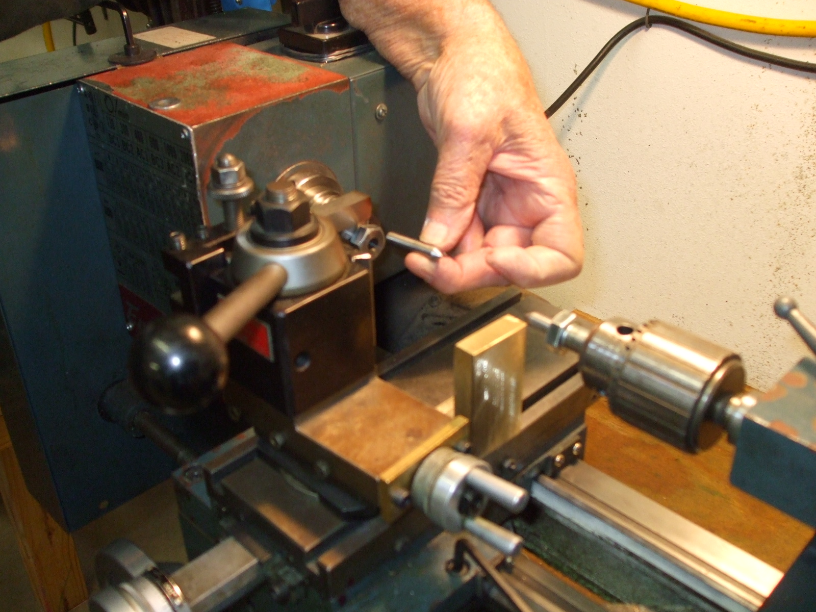
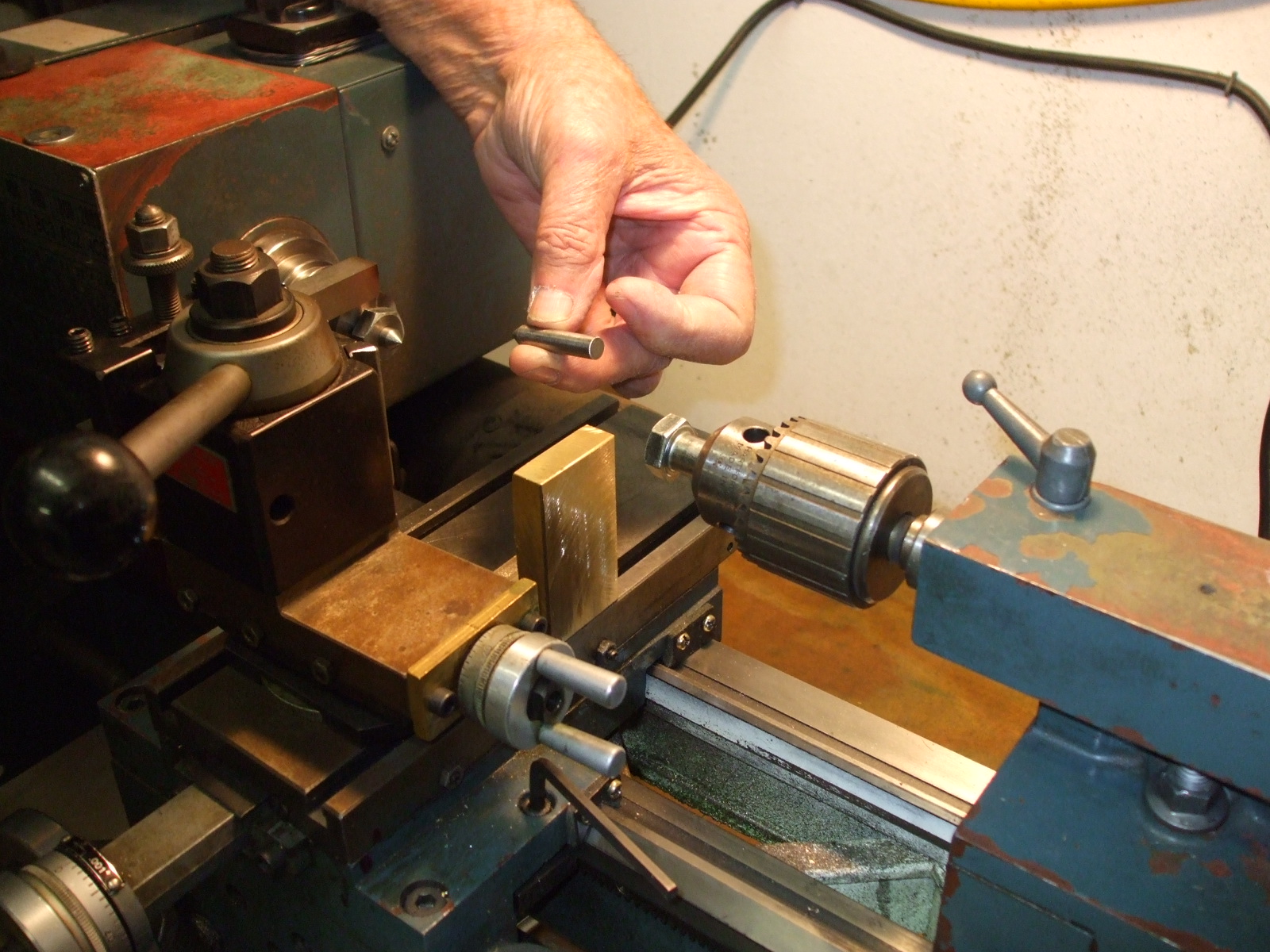
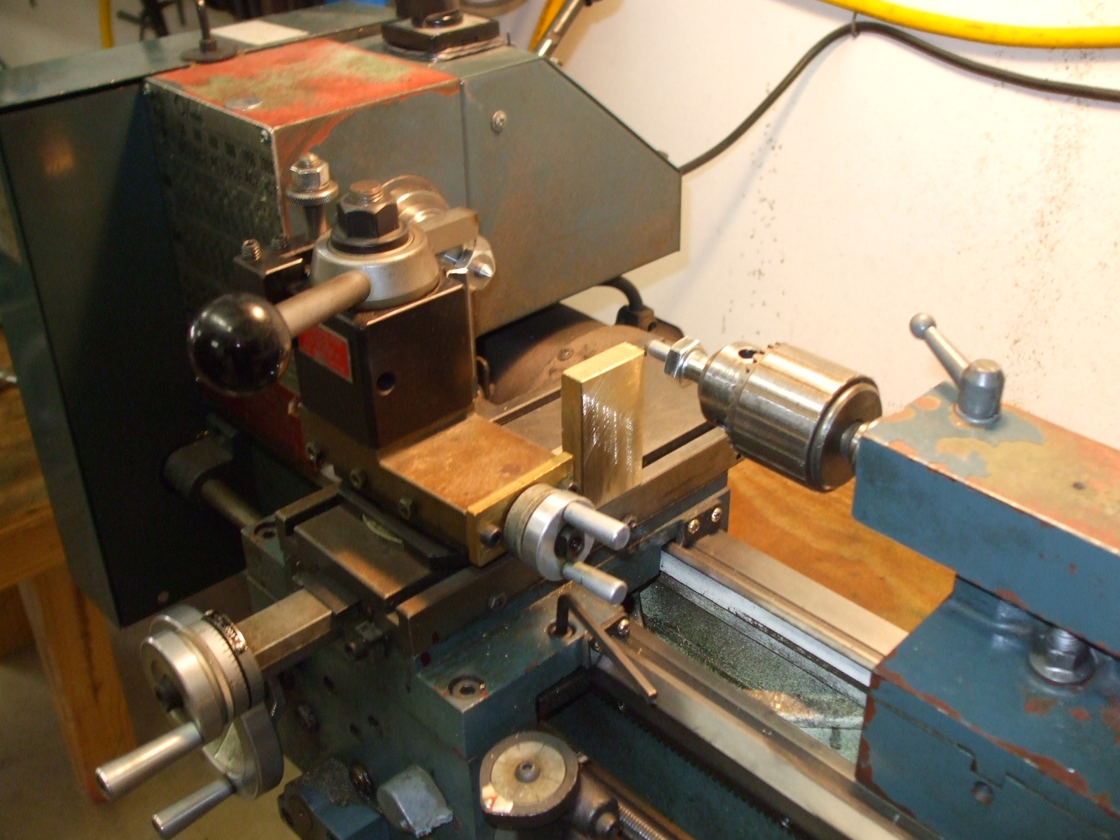
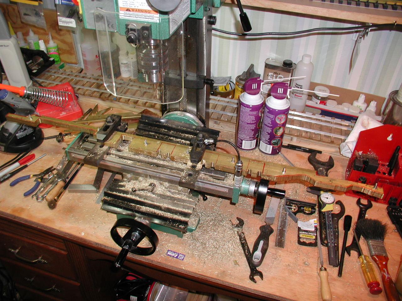
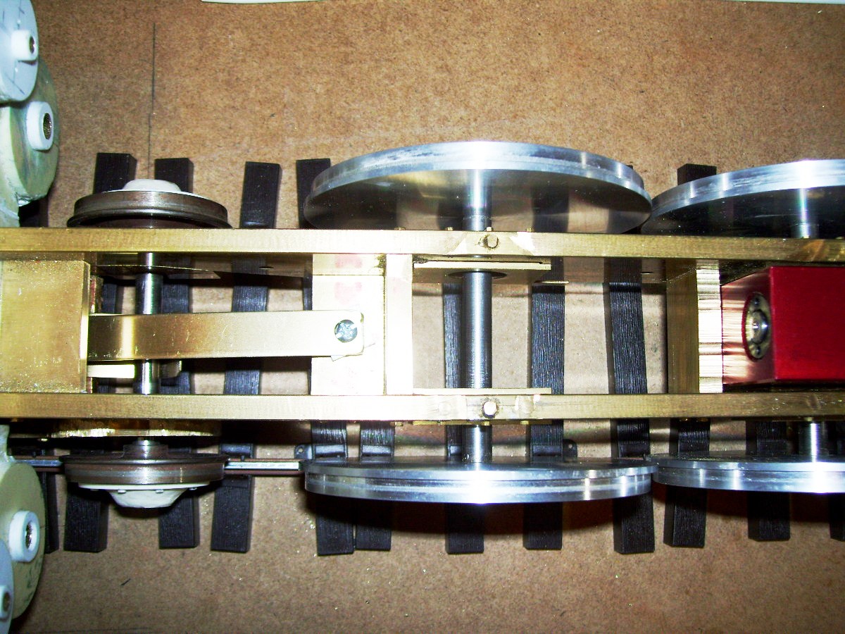
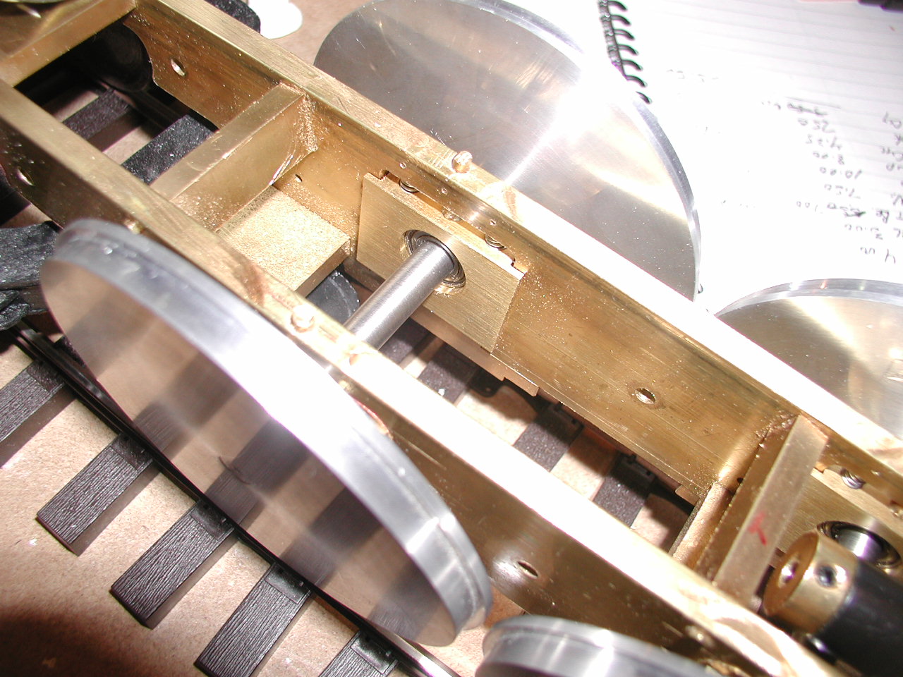
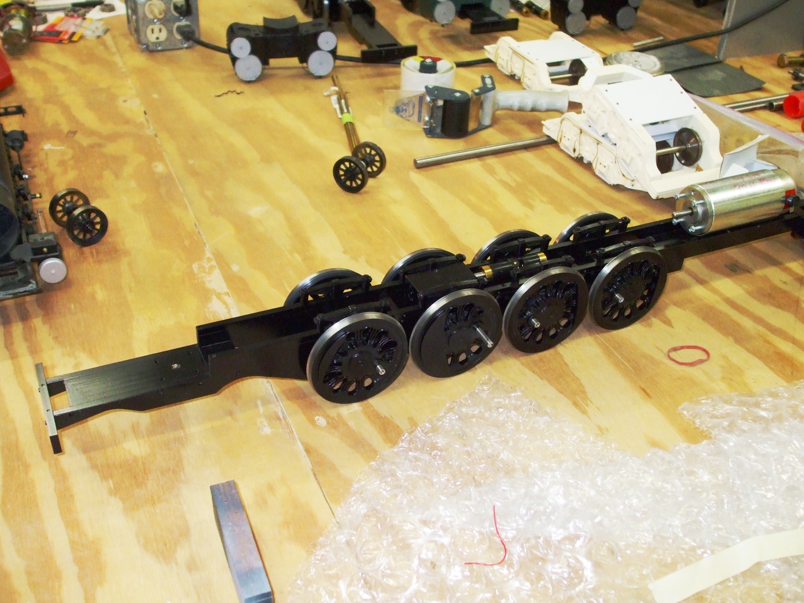
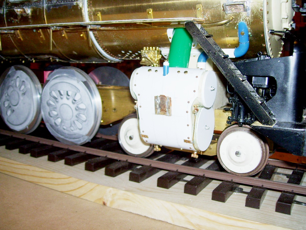
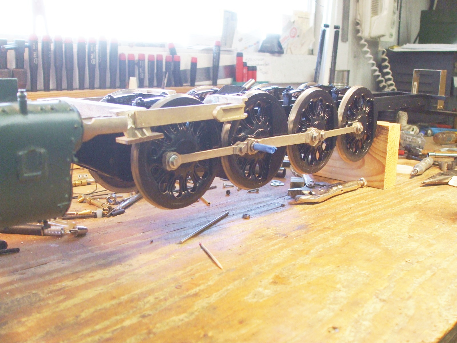
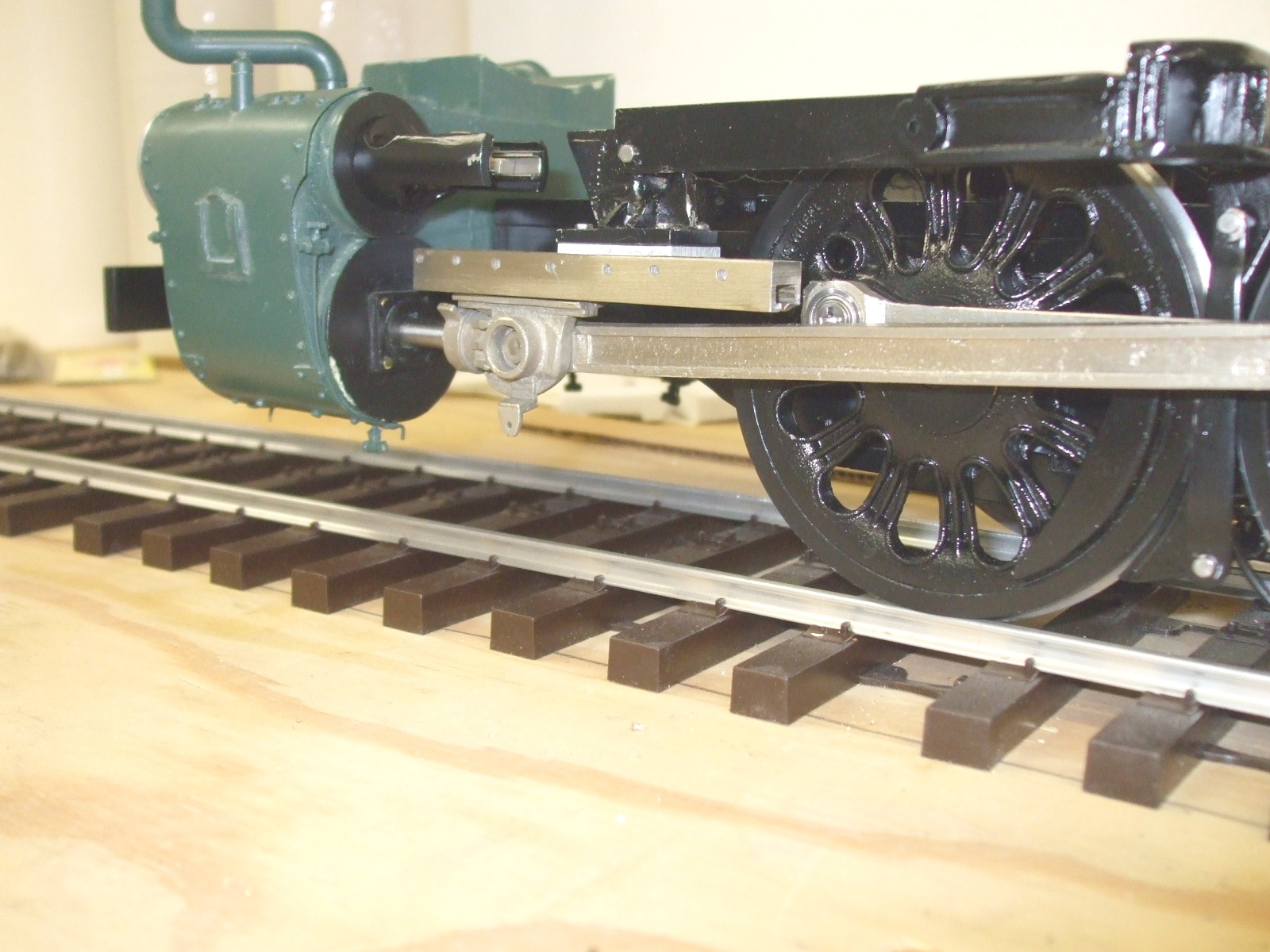
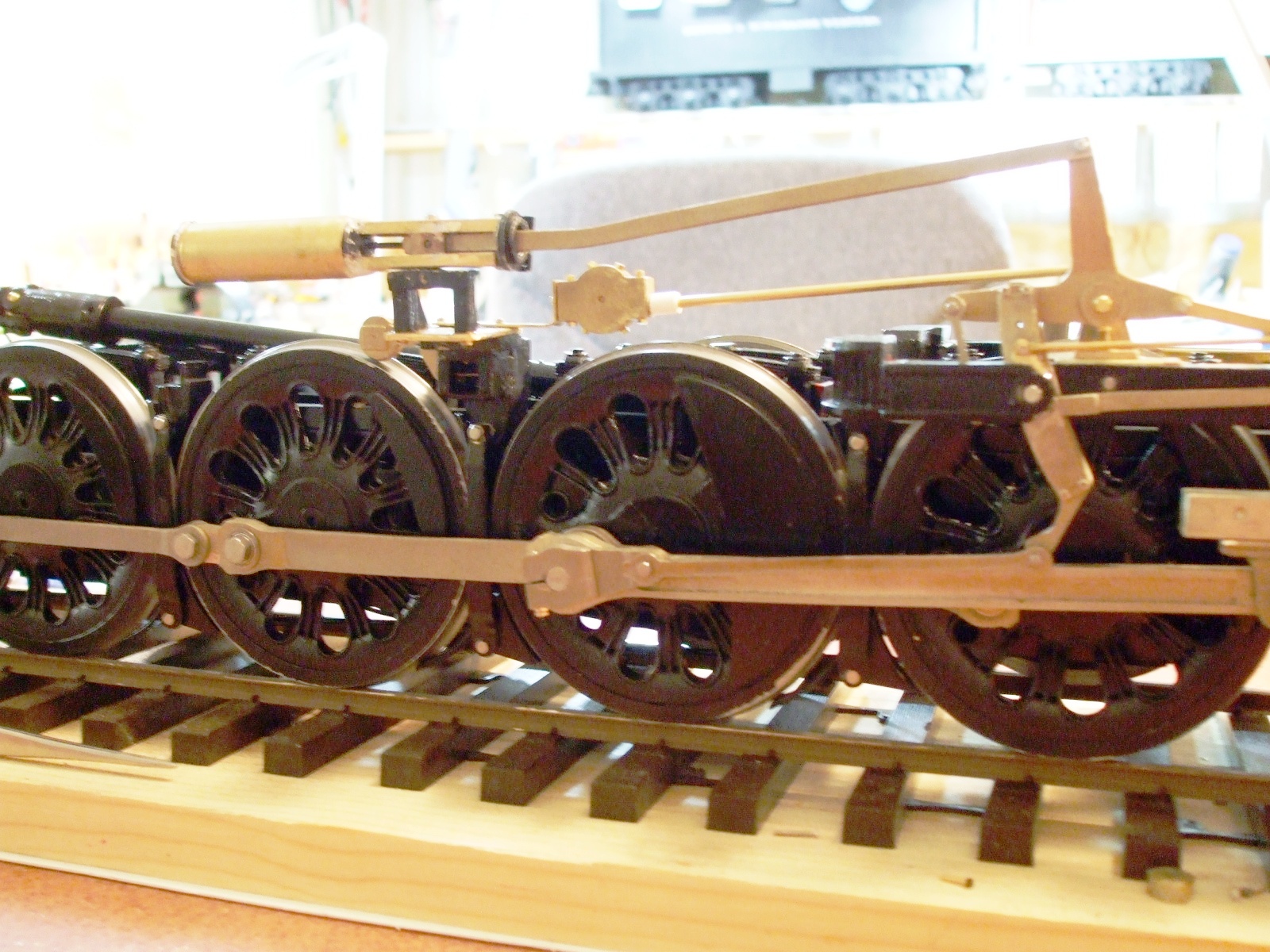
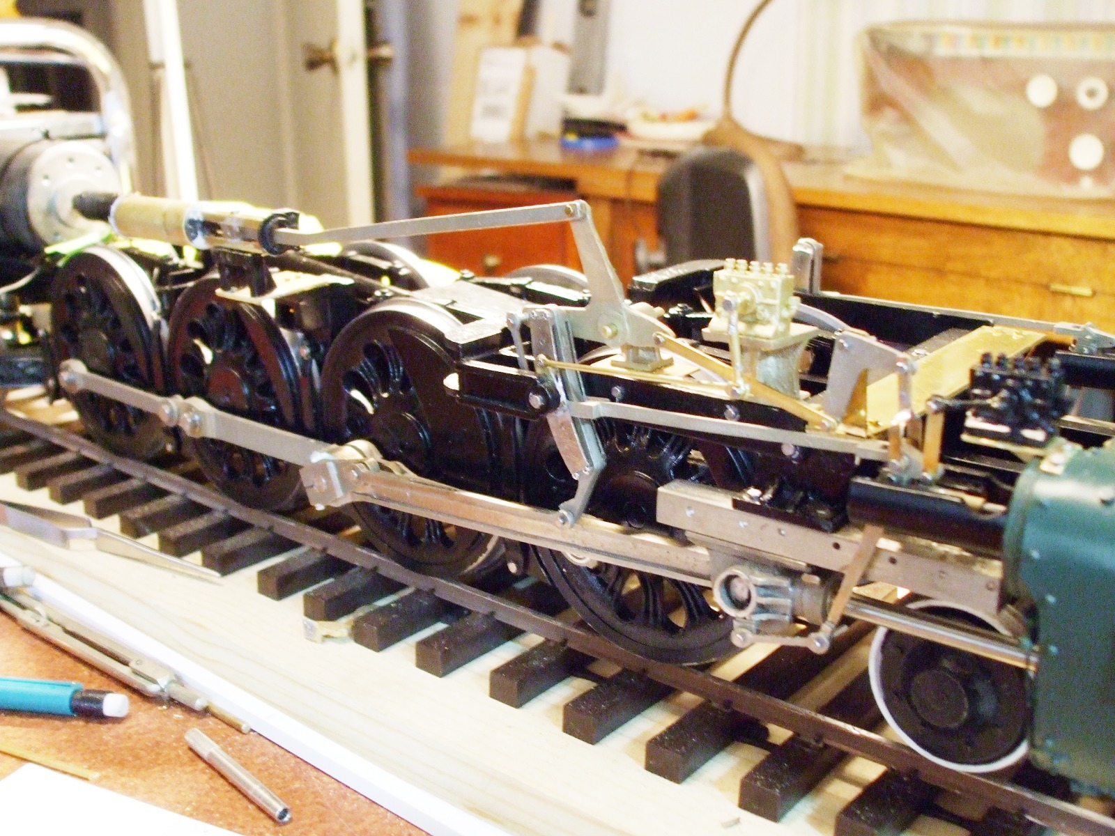
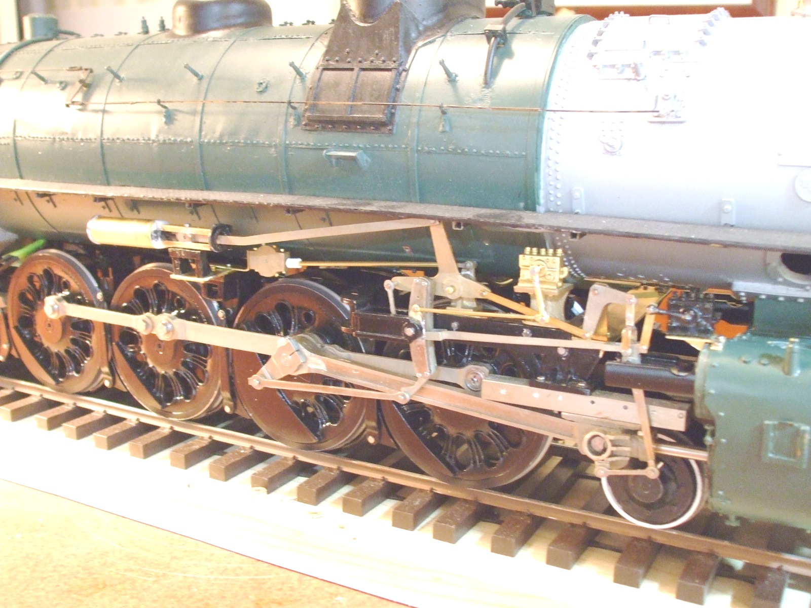
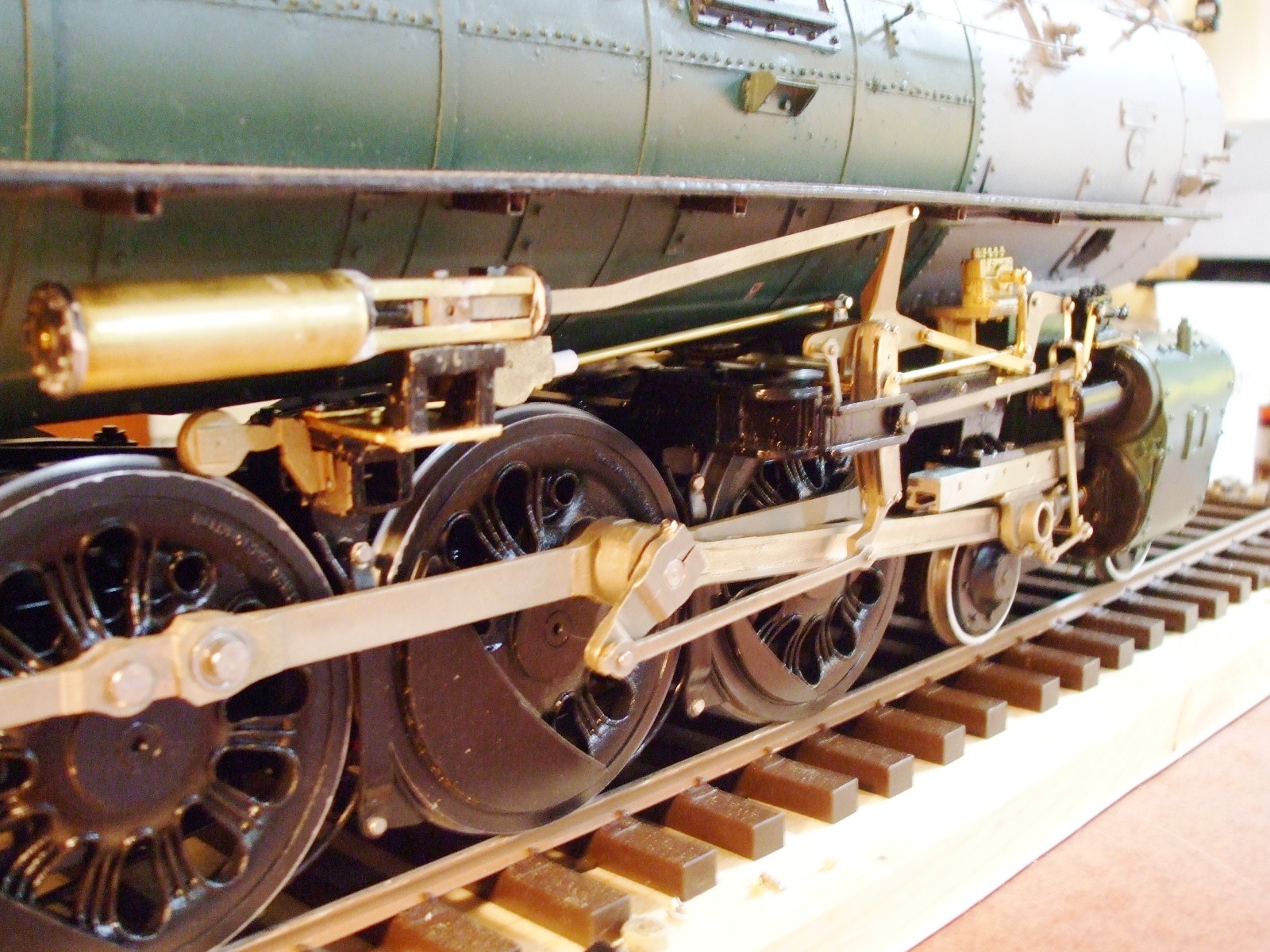
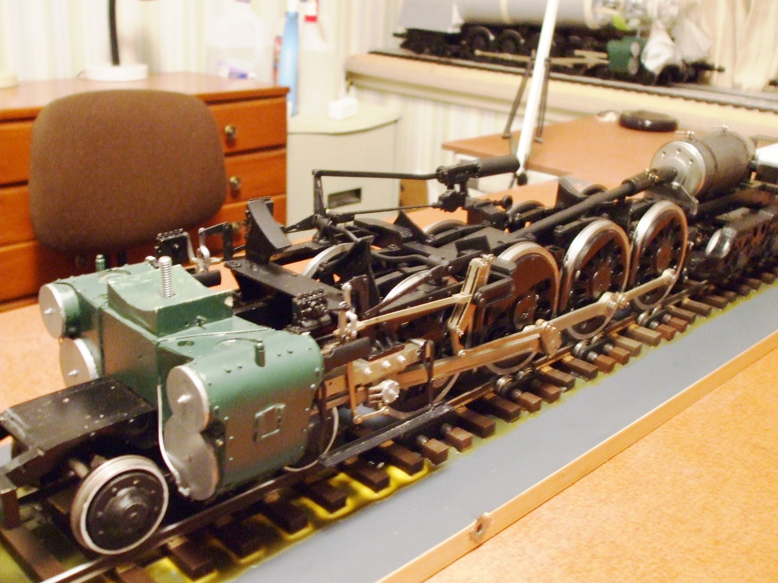
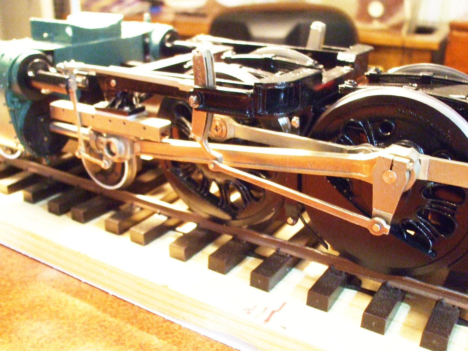
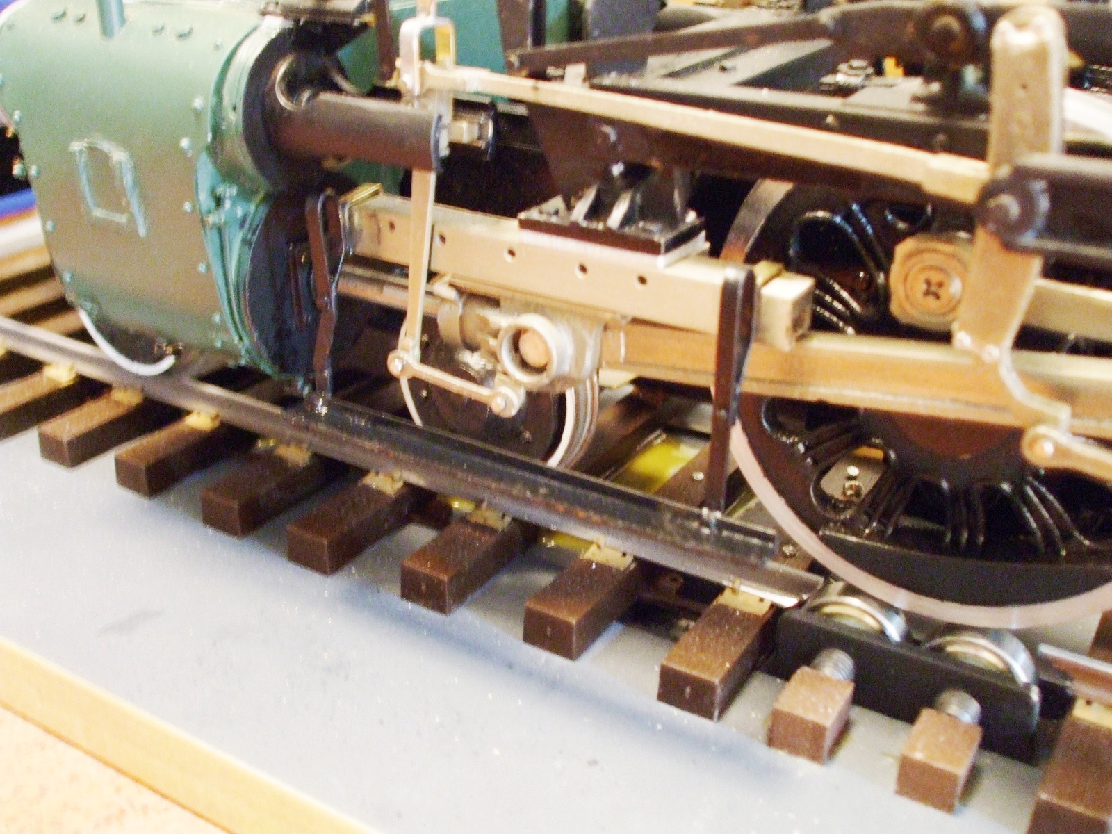
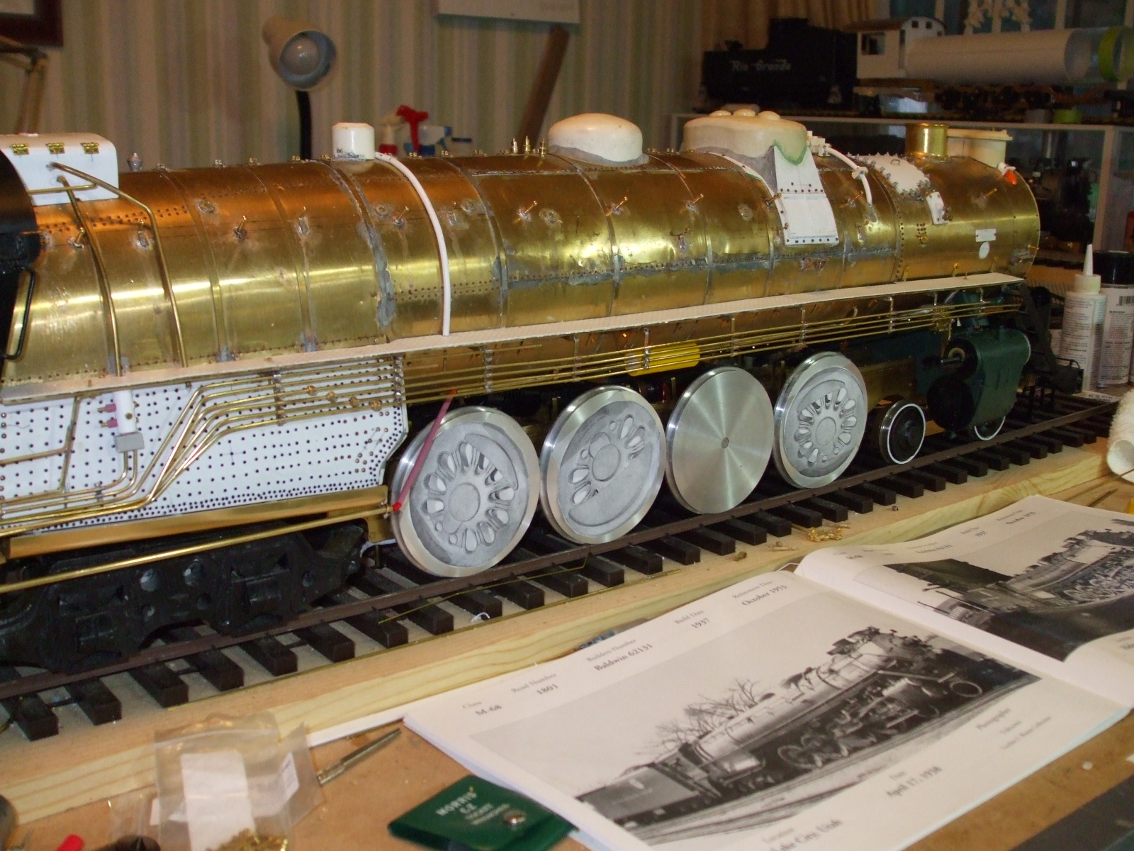
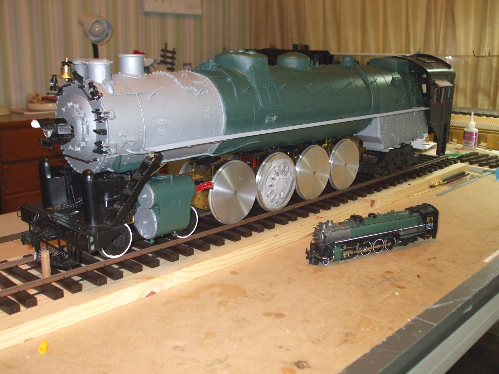
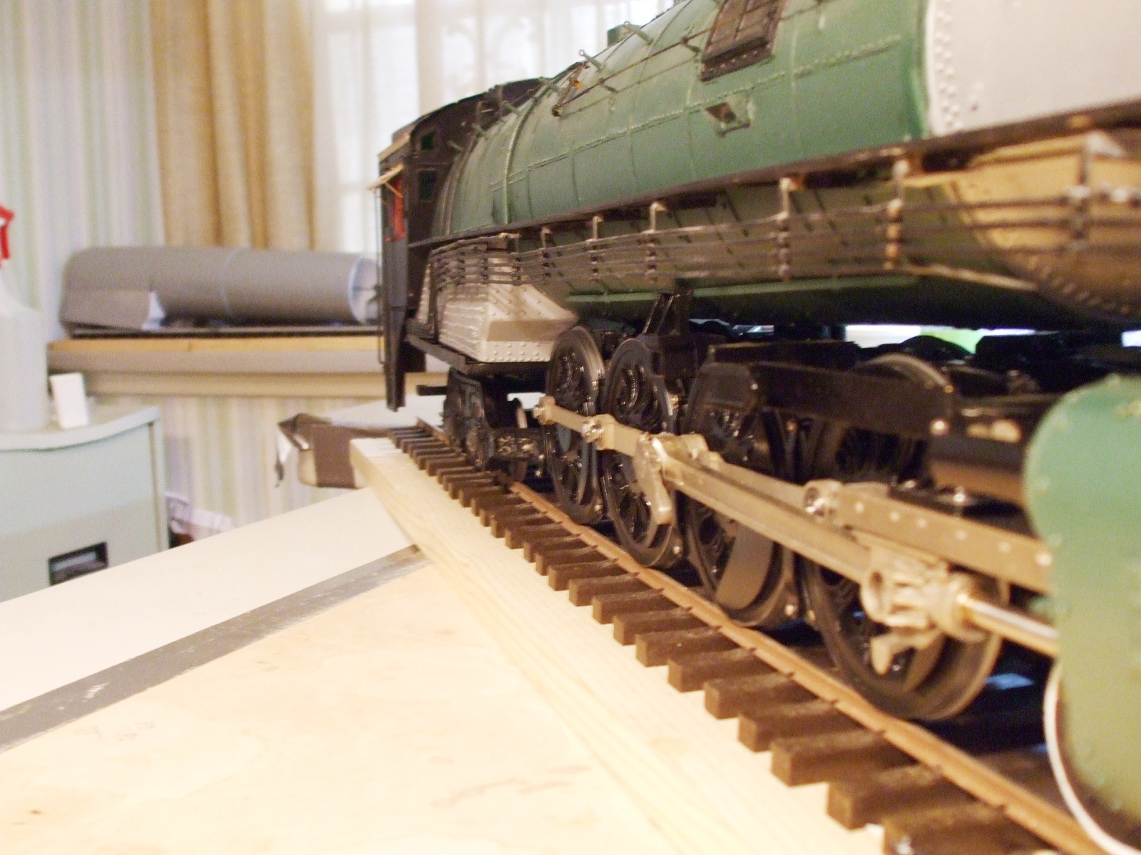
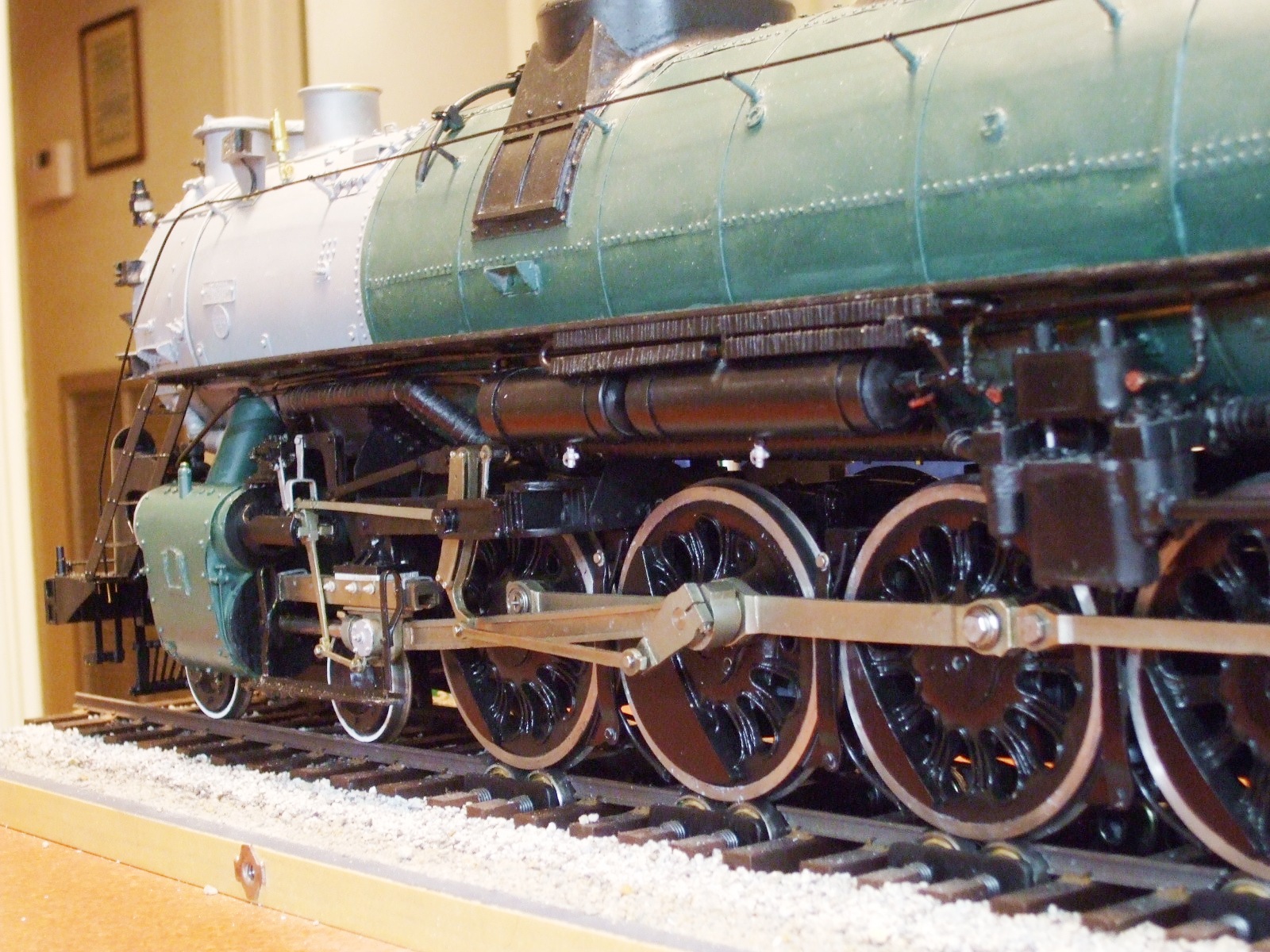
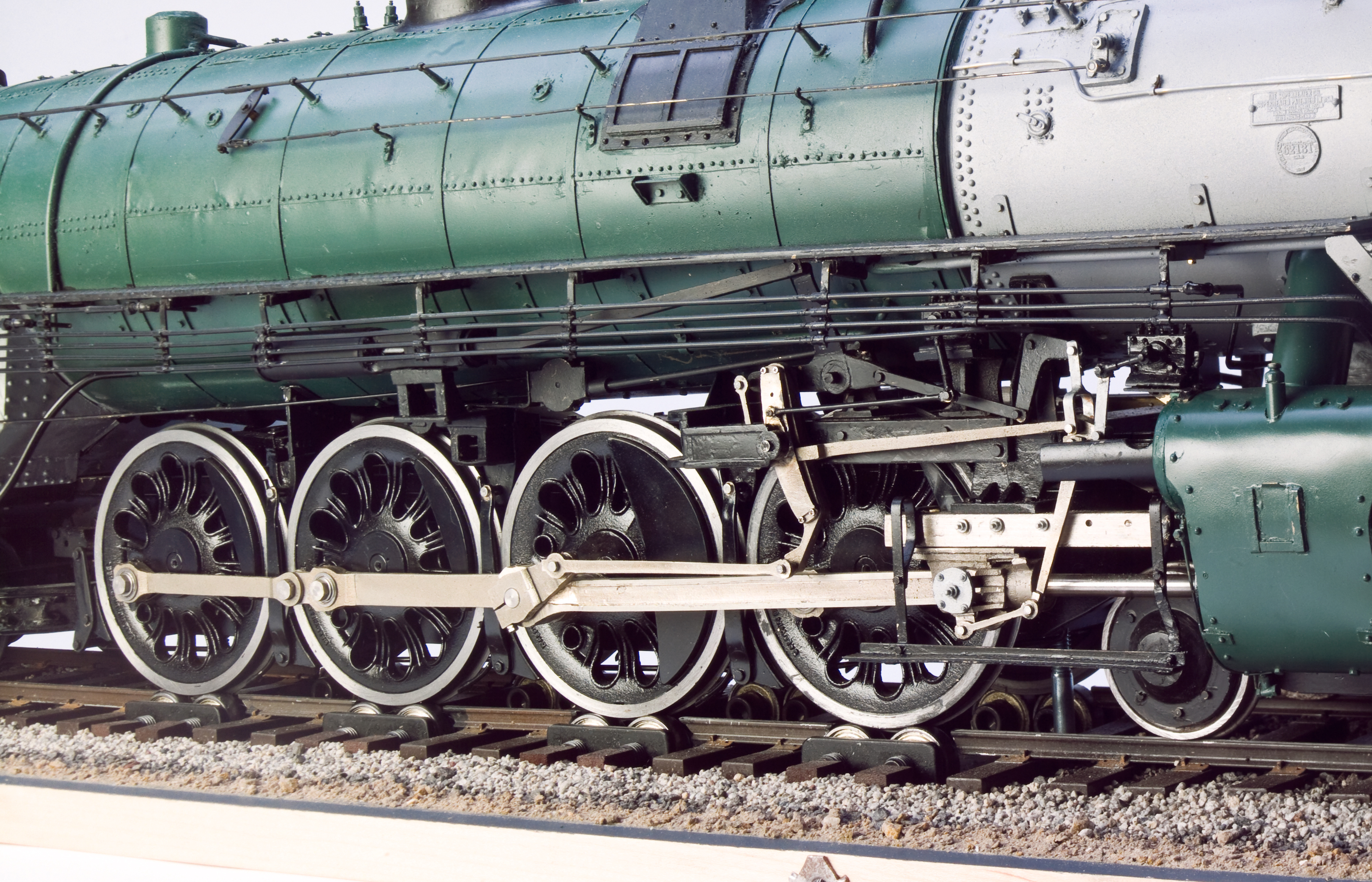
The Drivers
The machining and fitting of the driver centers to plain steel 73" driver tyres was done by the late Mr. Doug Cockerham in his shop outside of Houston. Doug faced both sides of the driver centers, turned them to the proper OD, and drilled the axle holes using his lathe's tailstock. He also made a cup-like jig for pressing the centers into their respective tyres. Each axle is turned from 1/4" mild steel and is shouldered. Since these locomotives are to be compatible with 2-rail electric operation, each tyre is electrically isolated from its driver center using a thin section of .005" mylar, pressed between the tyre and the driver center.
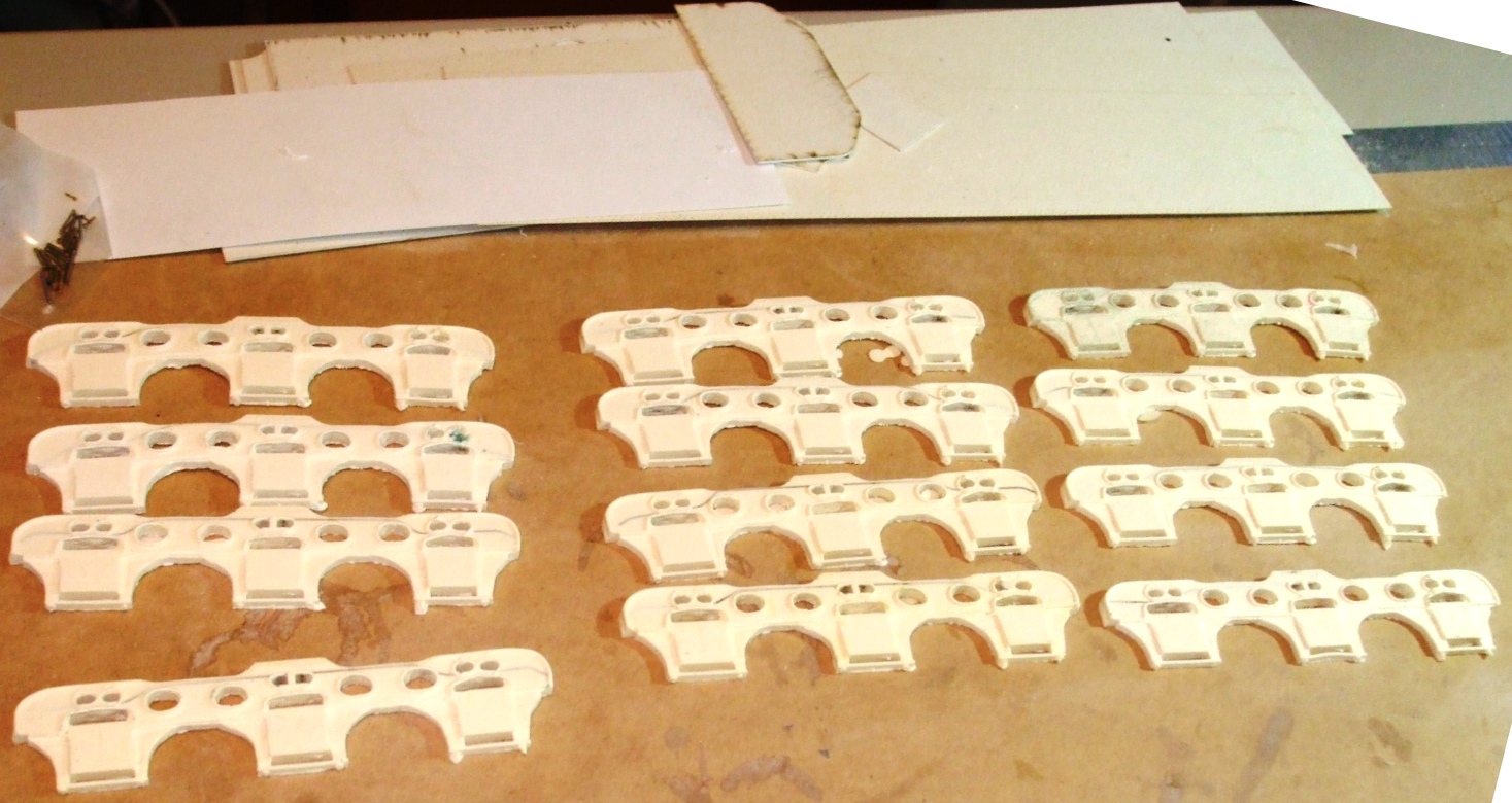
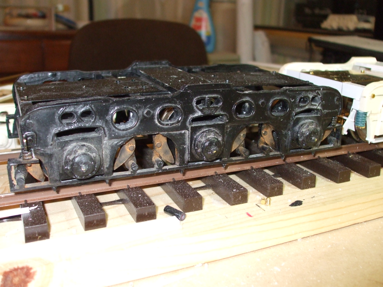
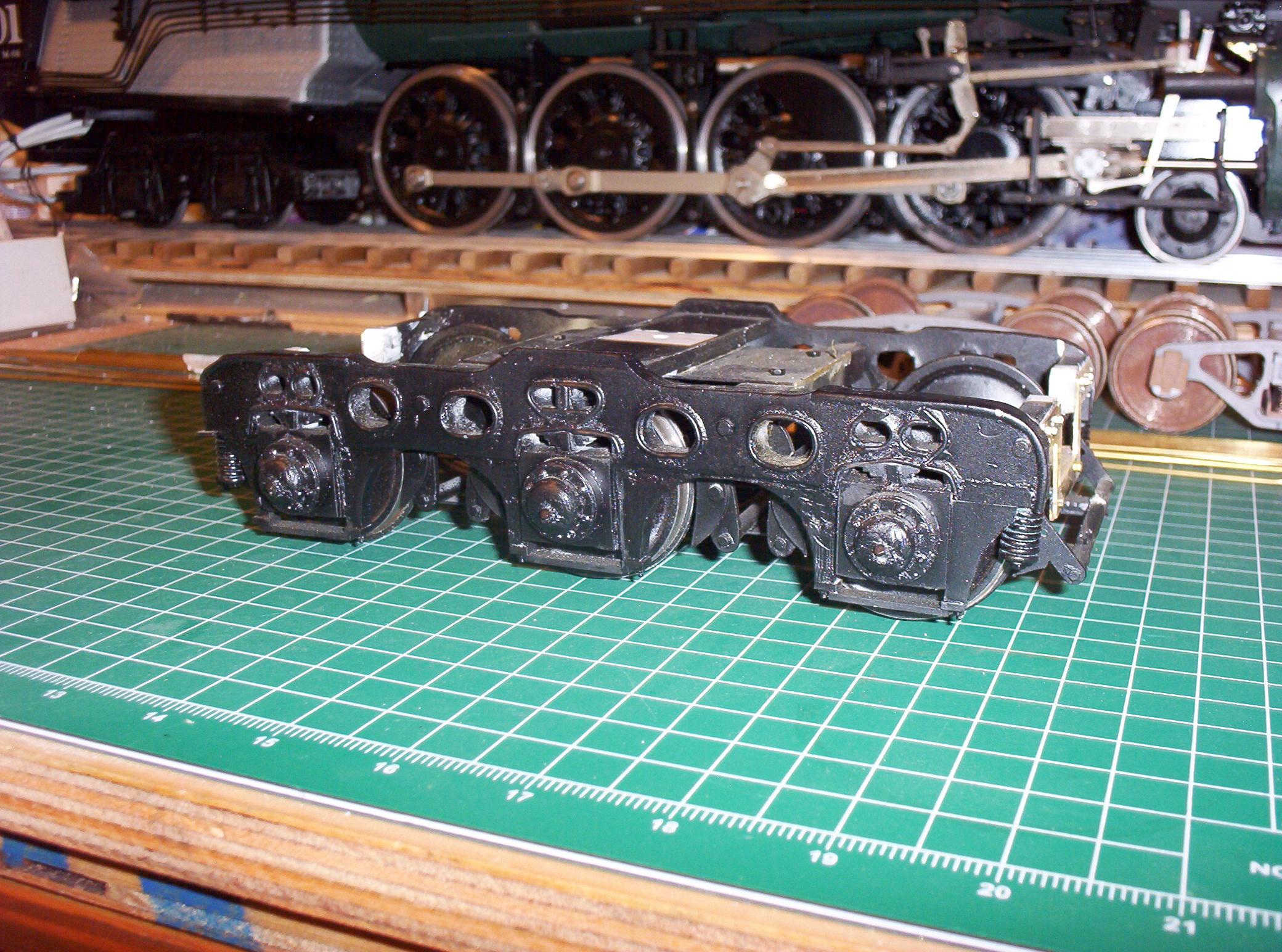
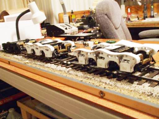
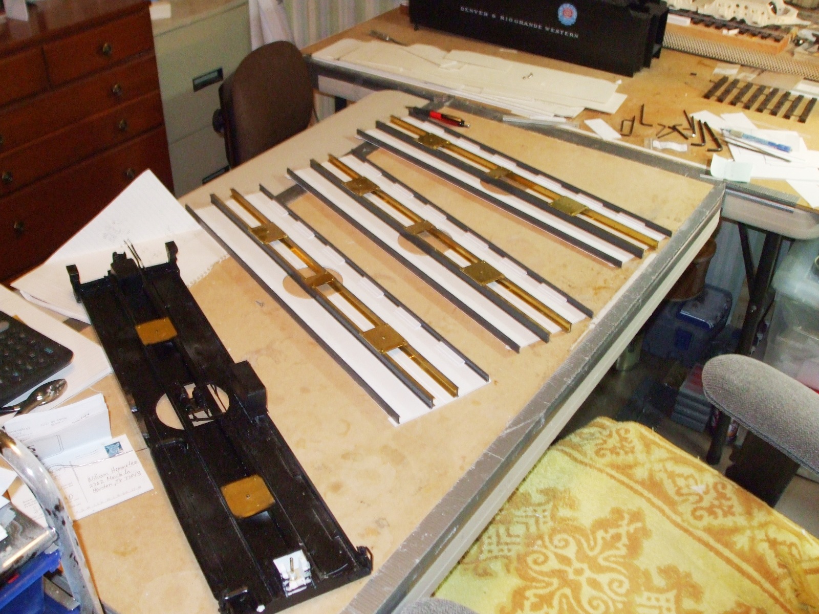
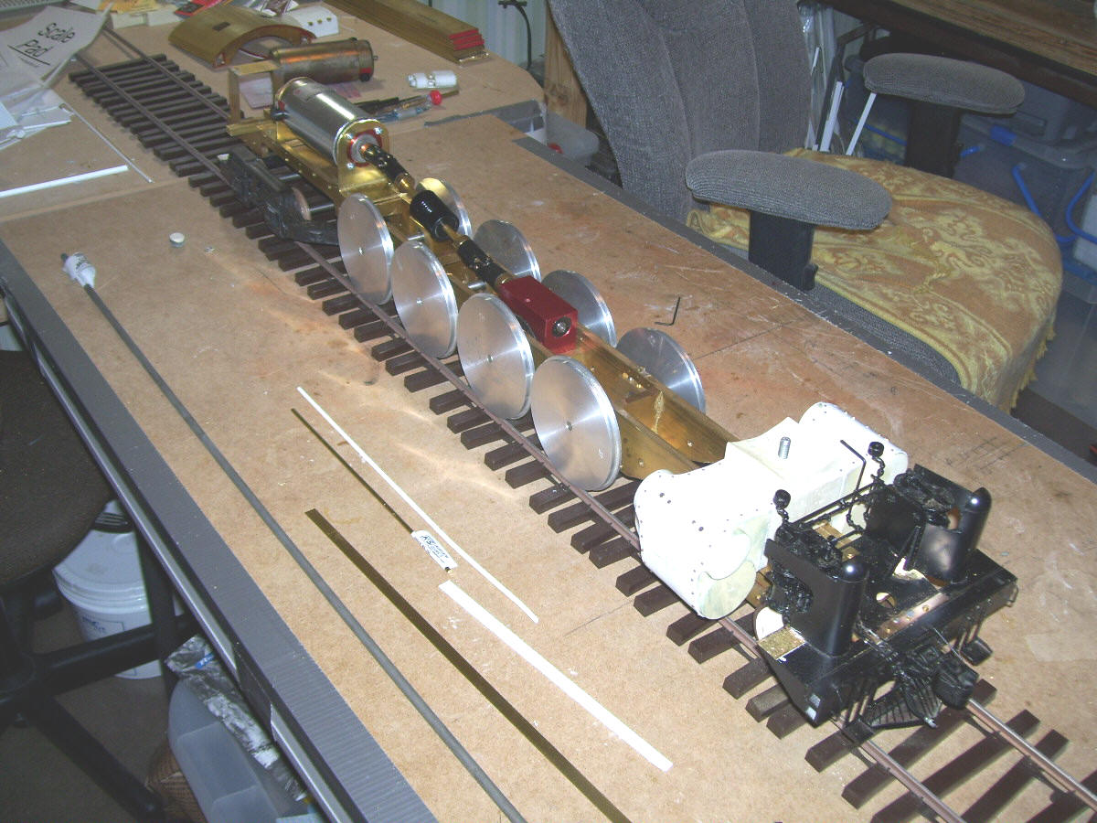
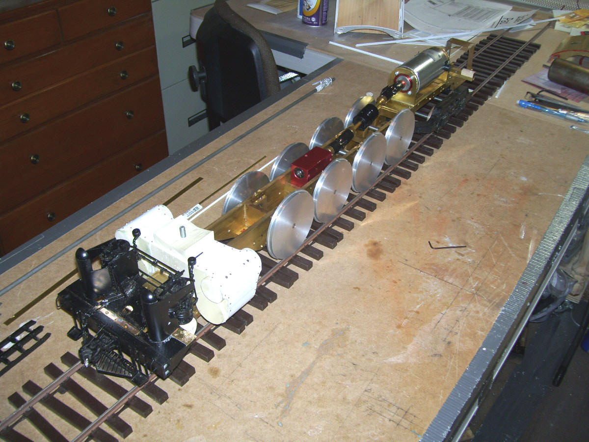
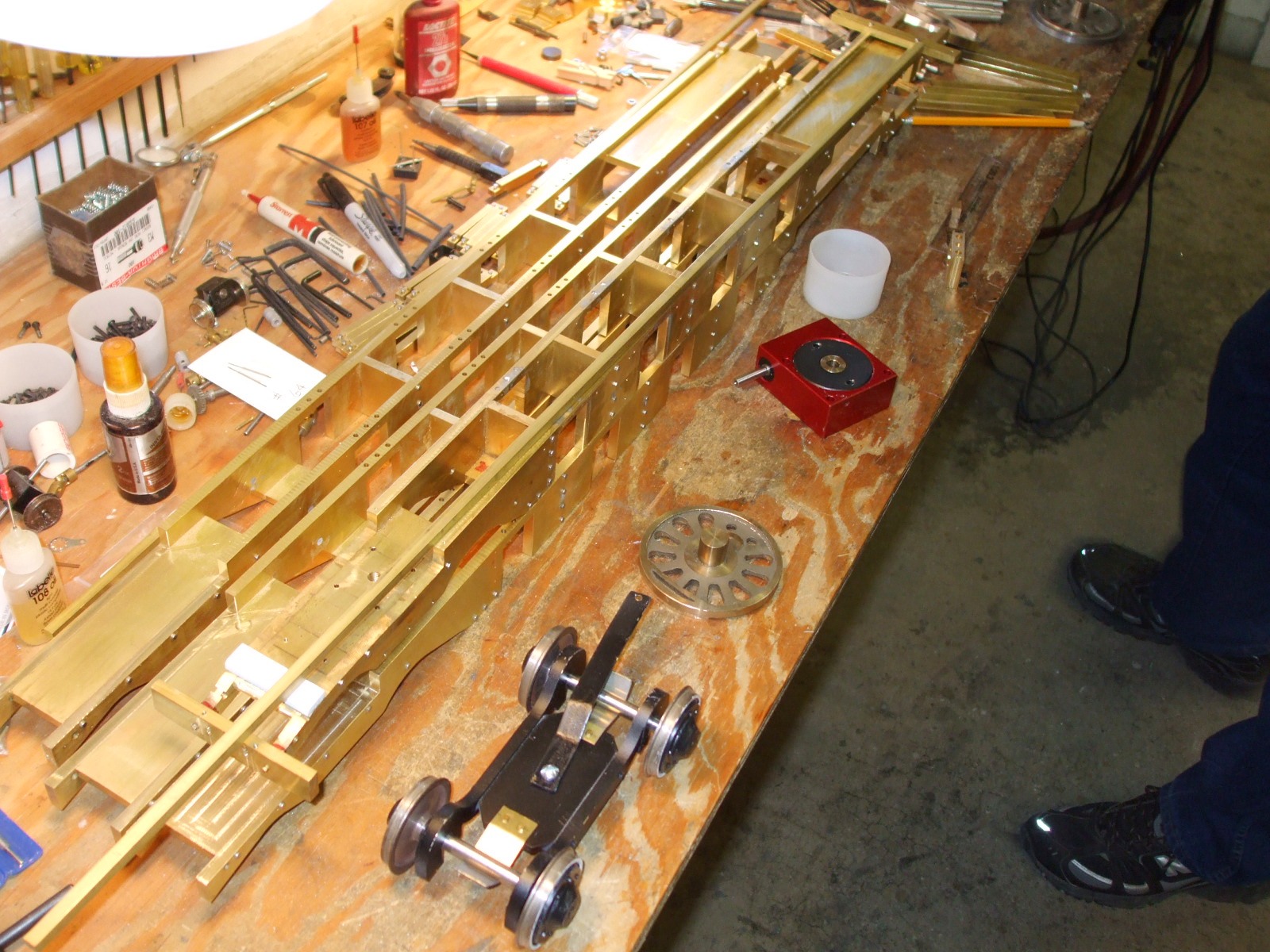
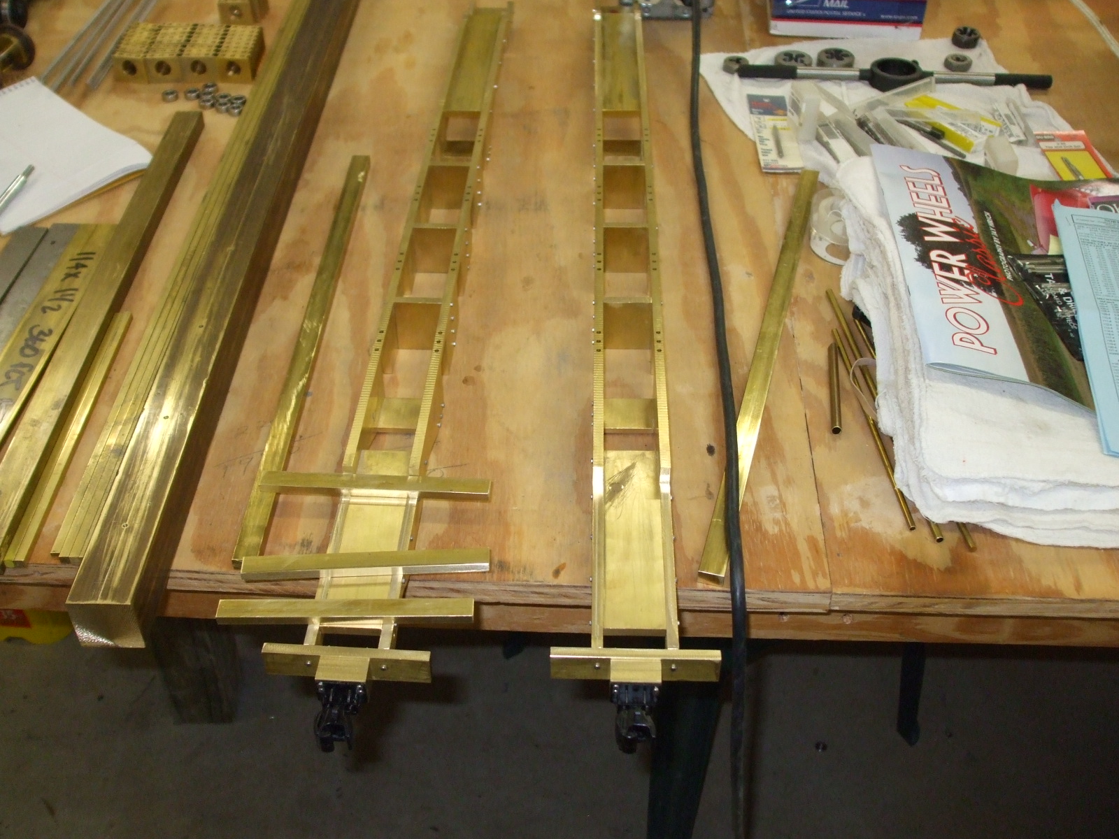
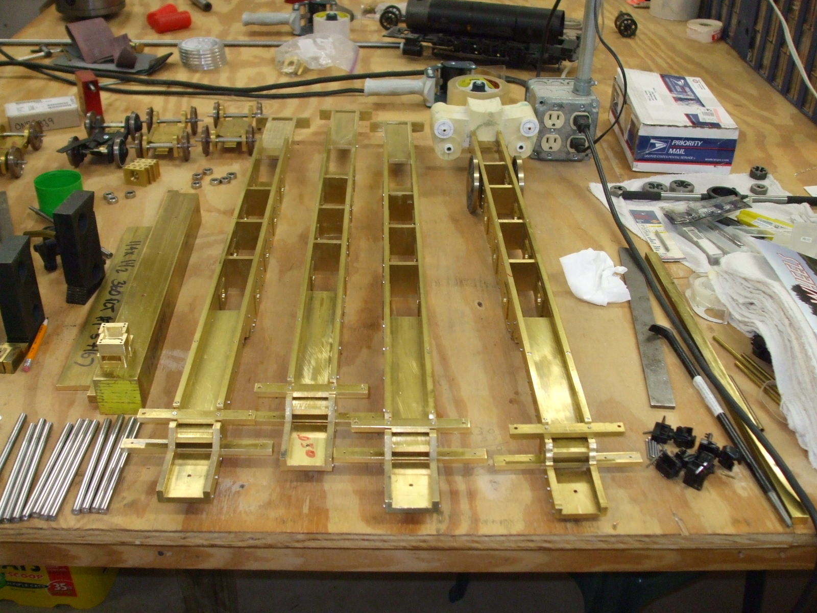
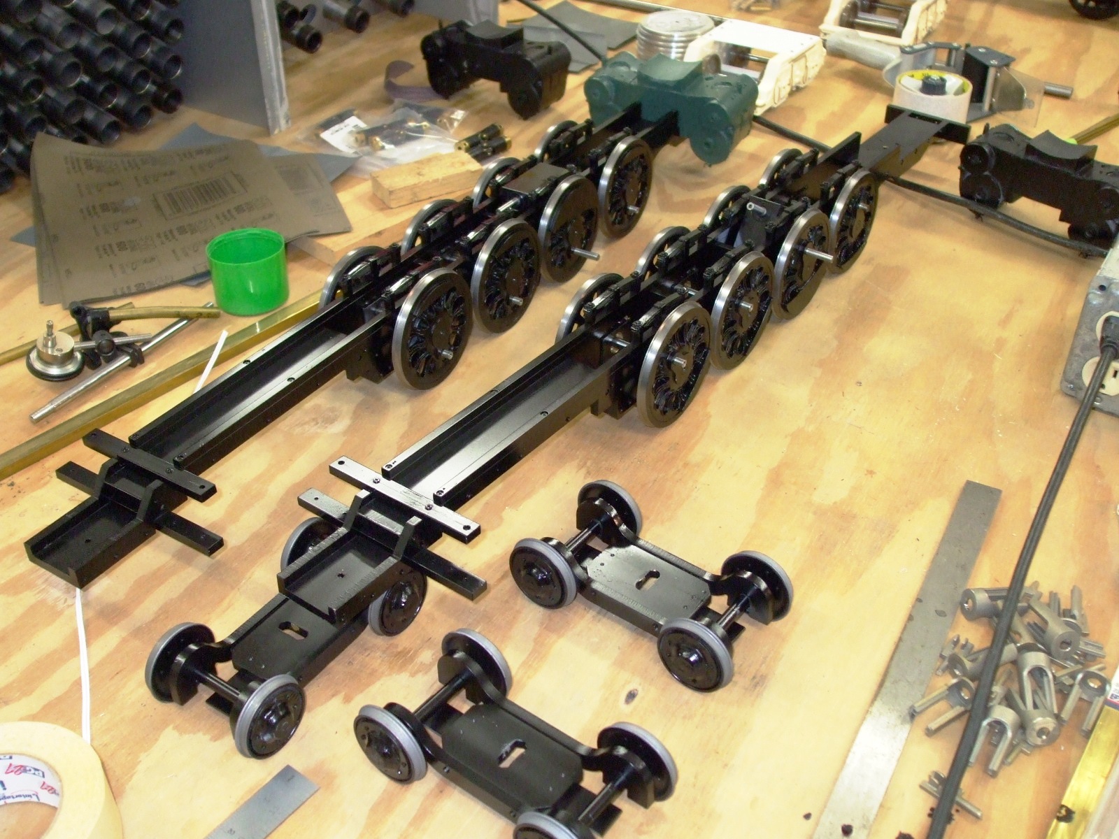
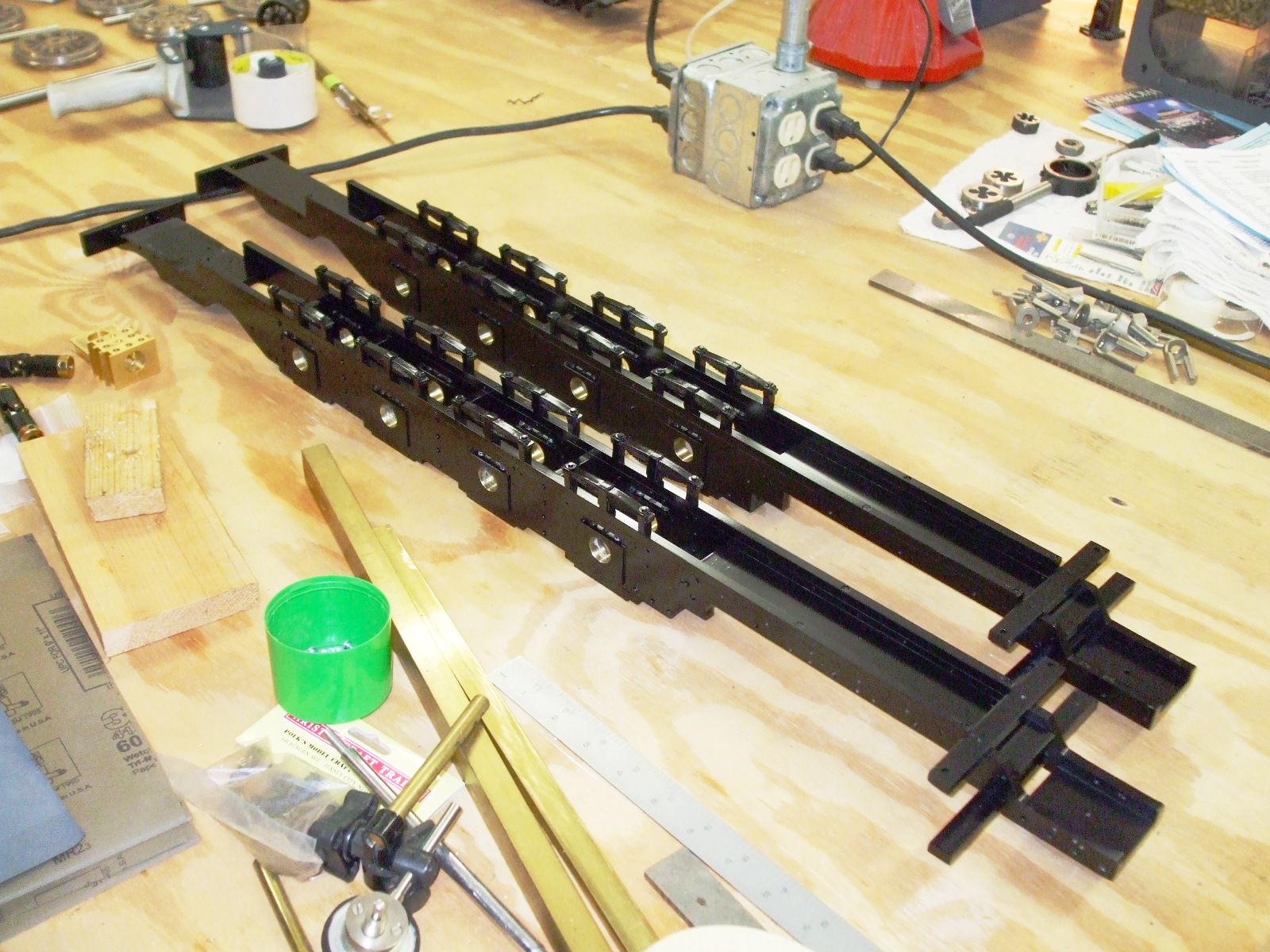
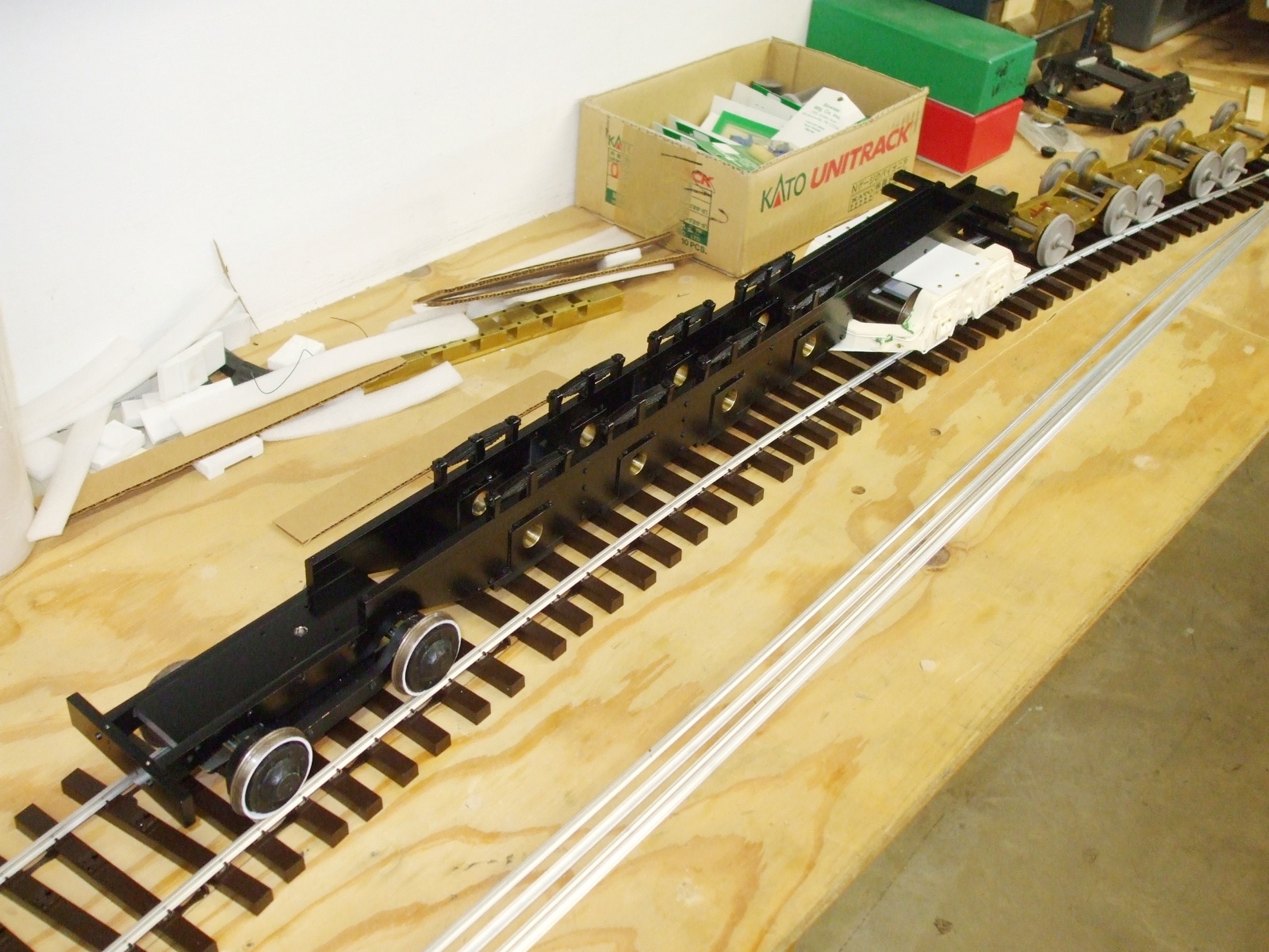
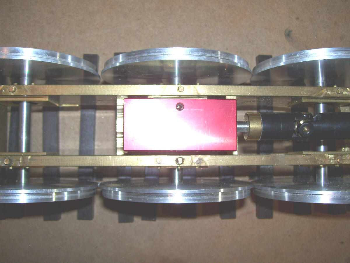
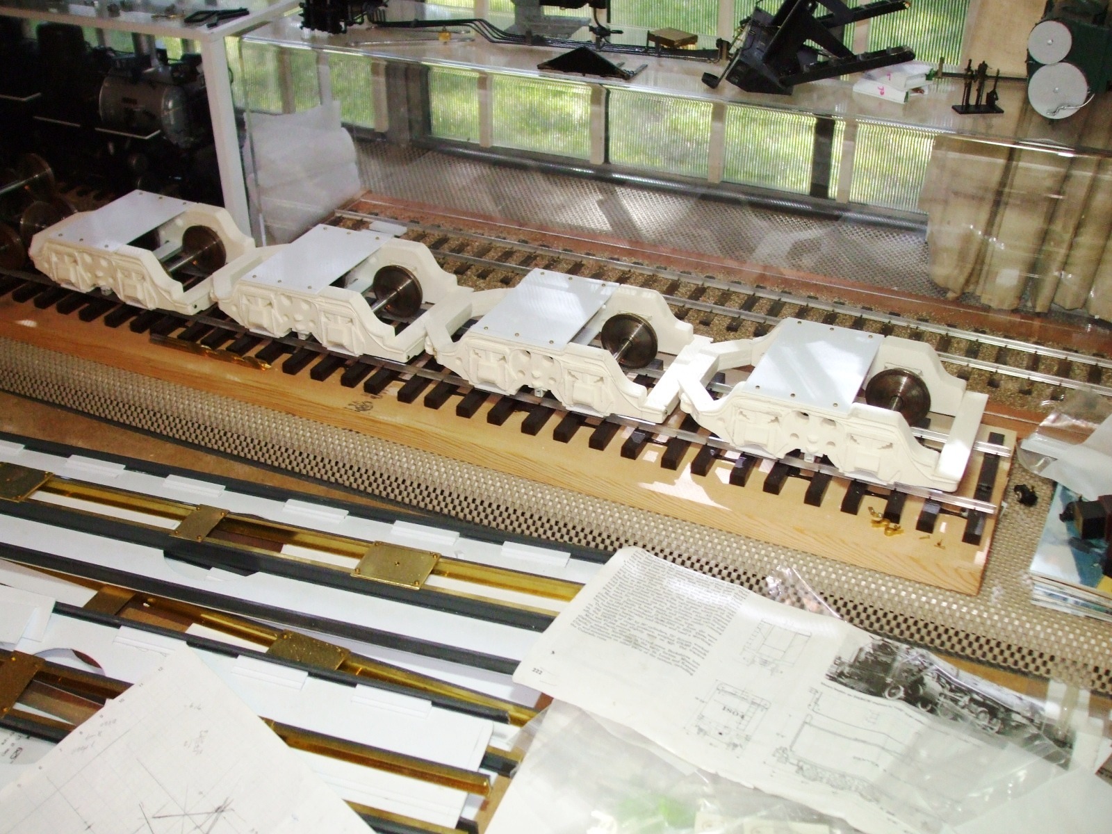
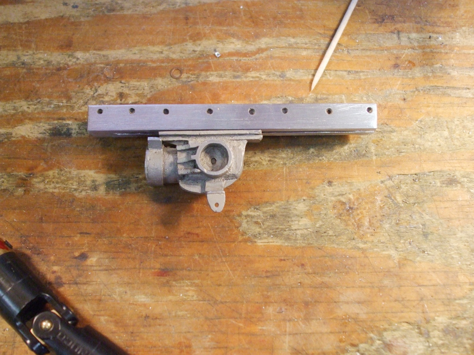
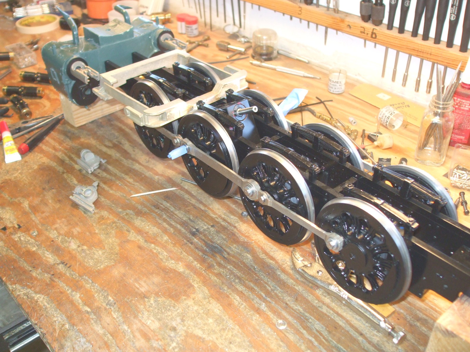
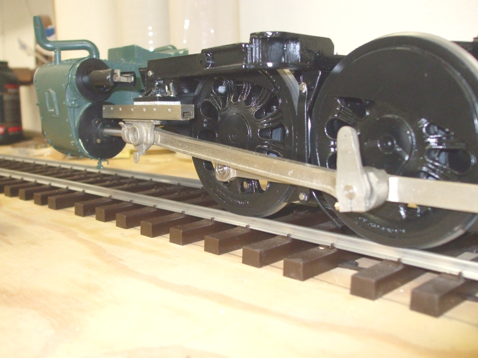
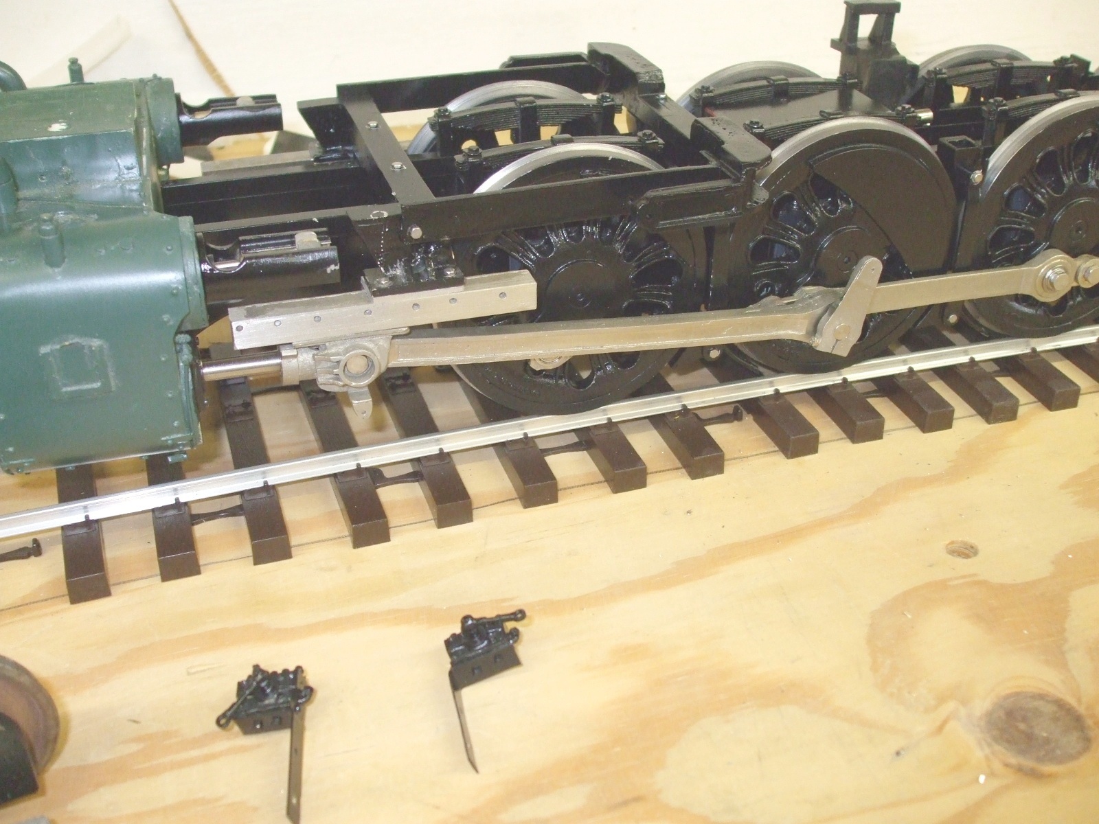
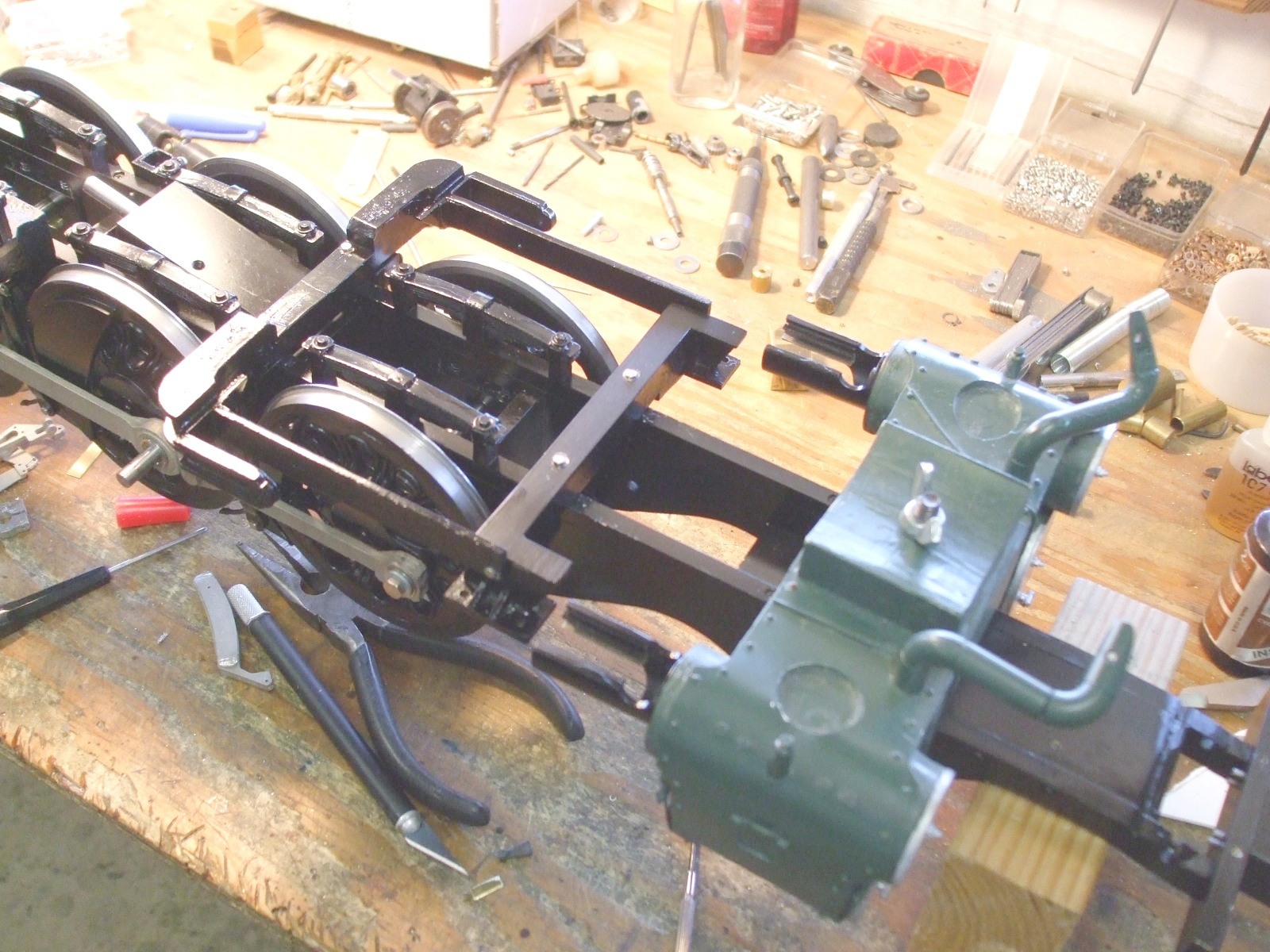
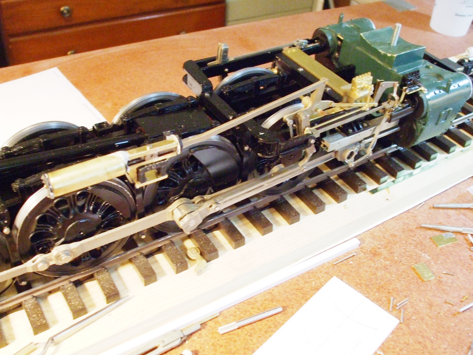
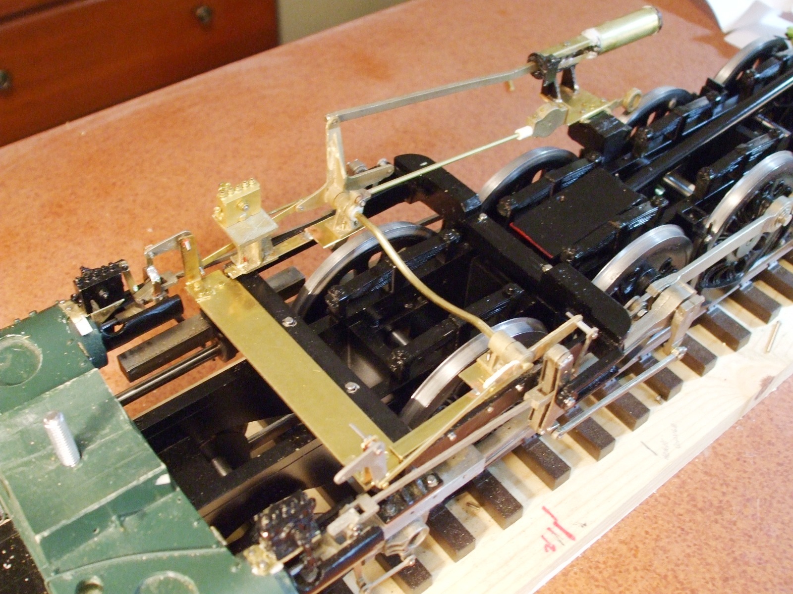
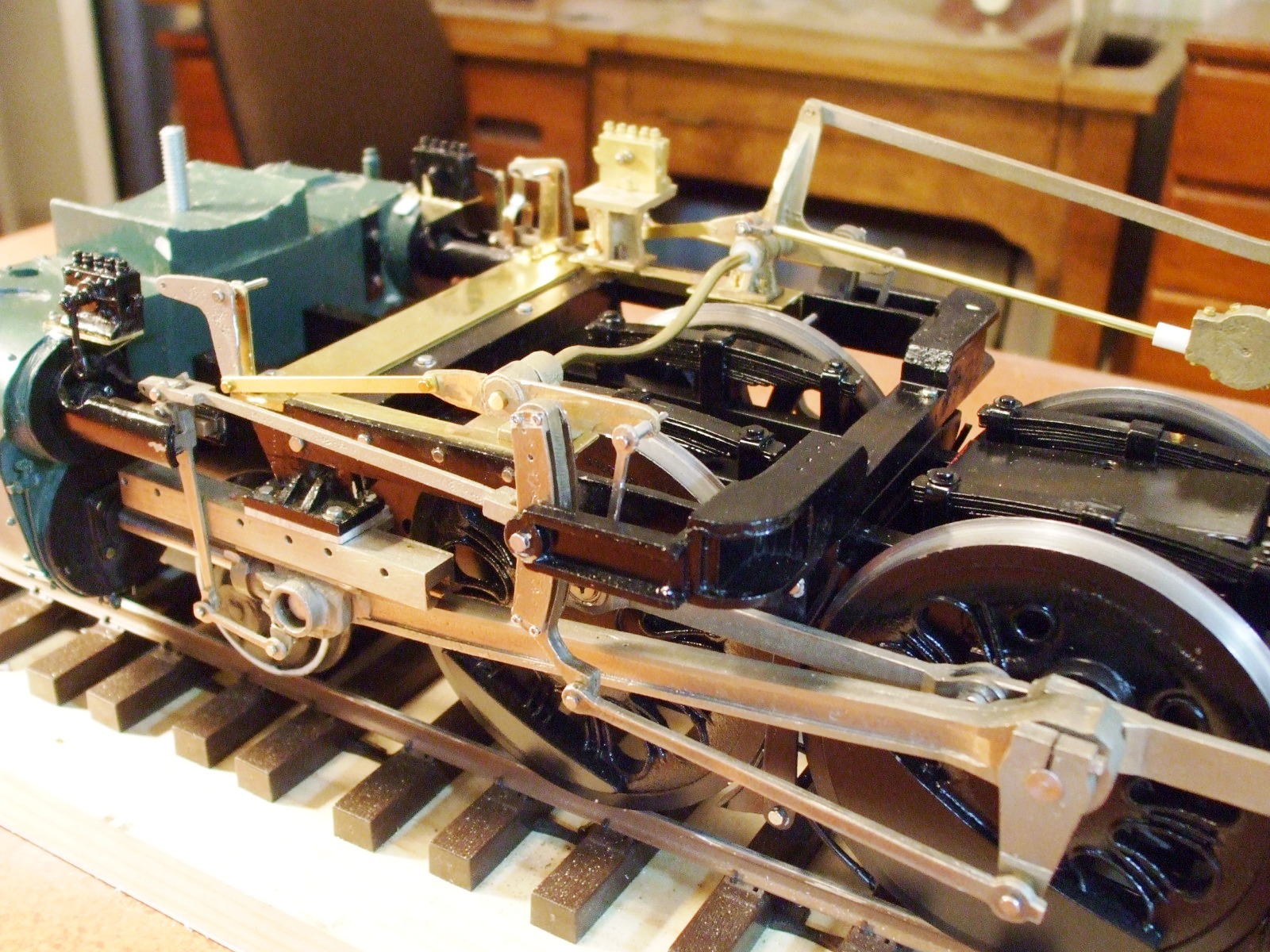
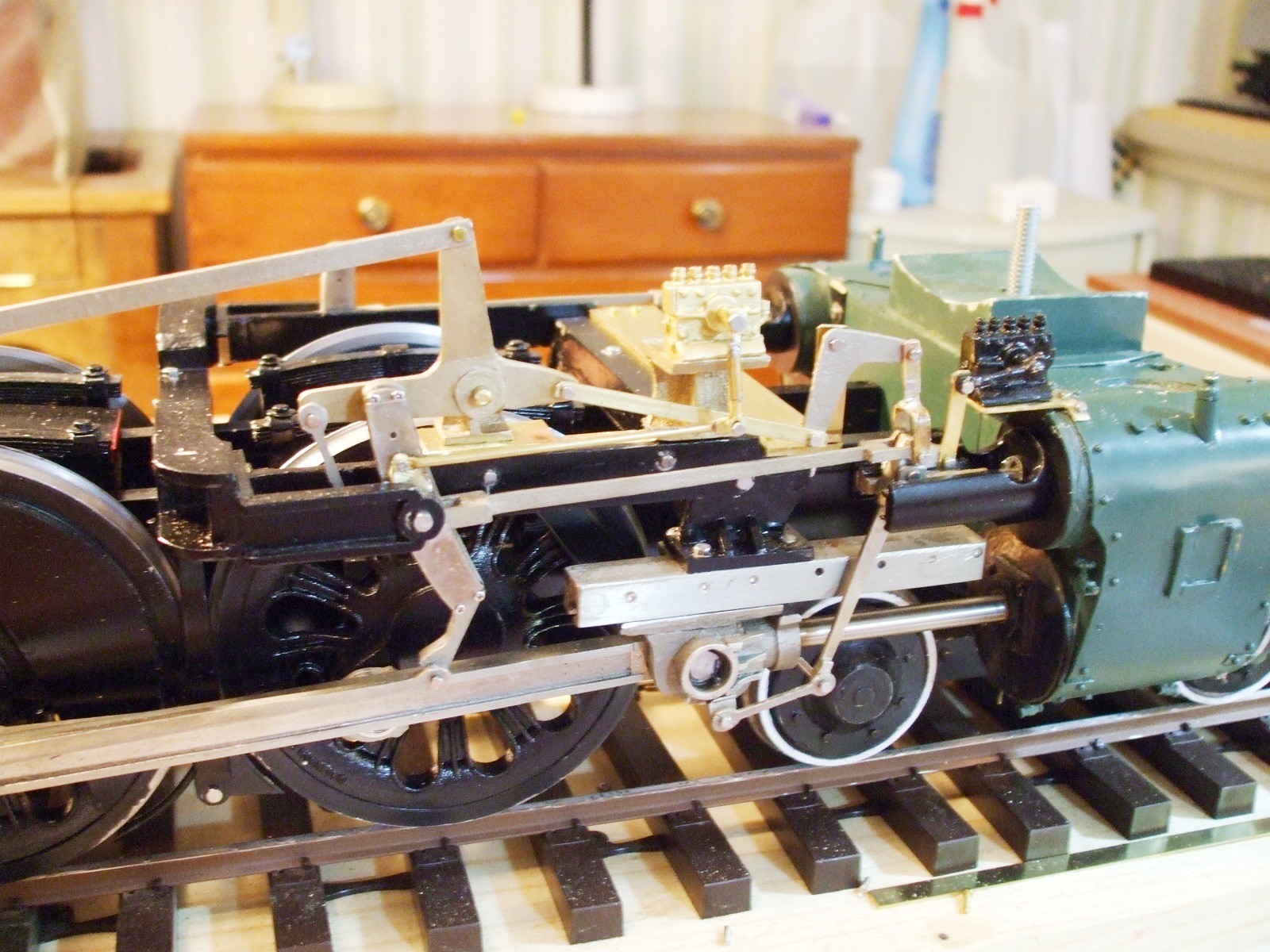
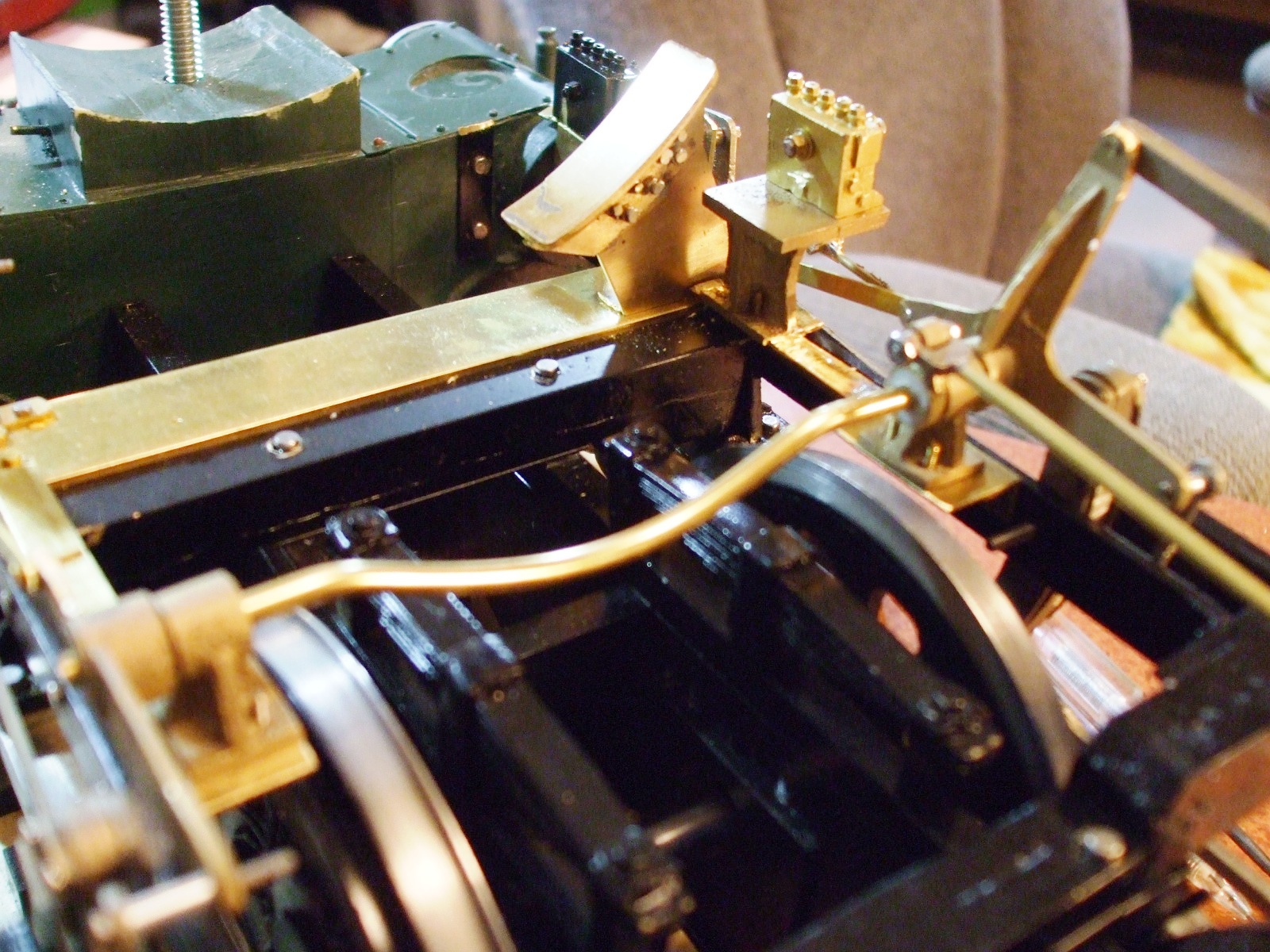
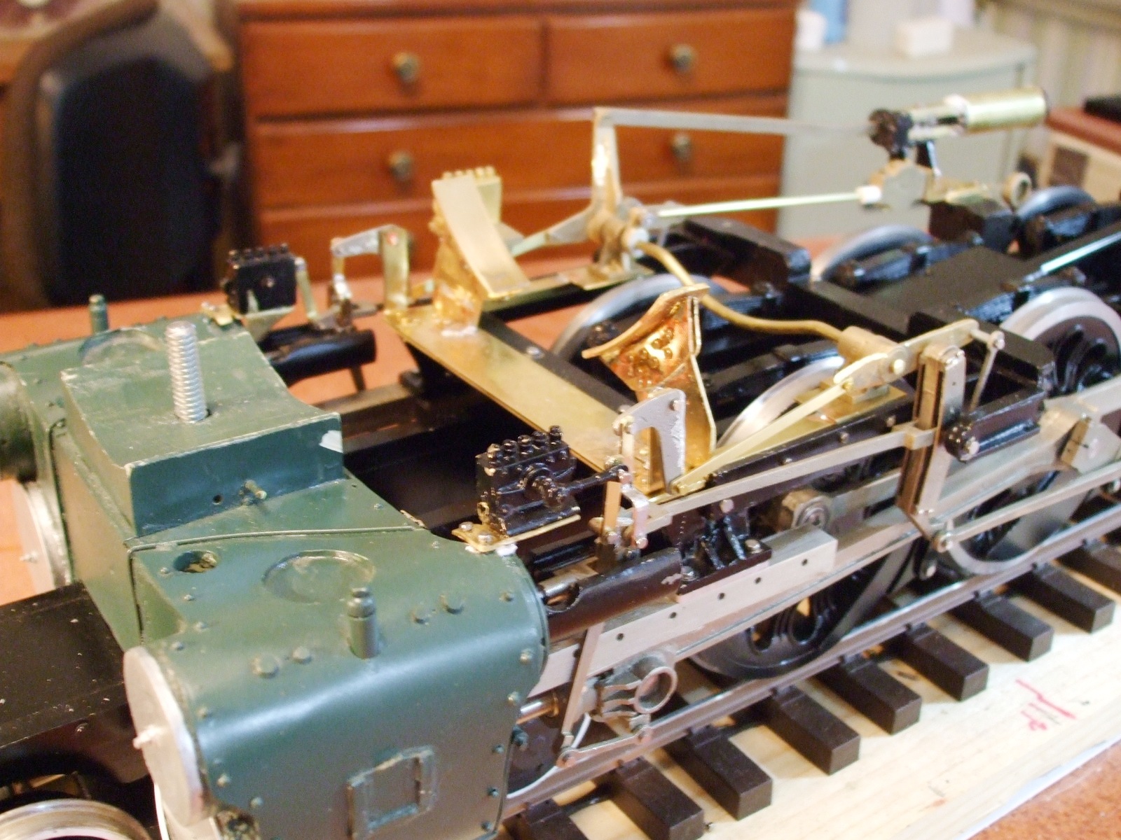
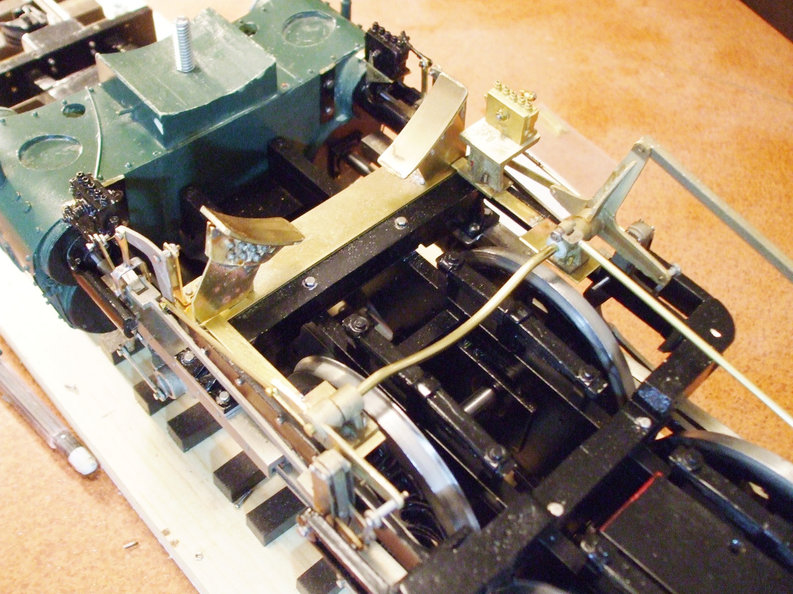
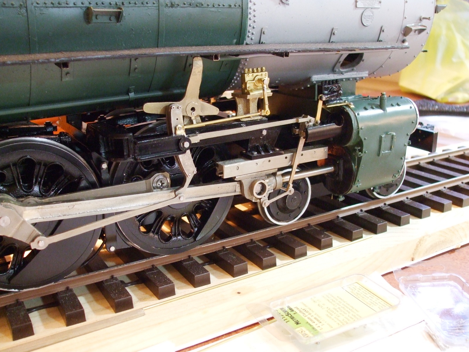
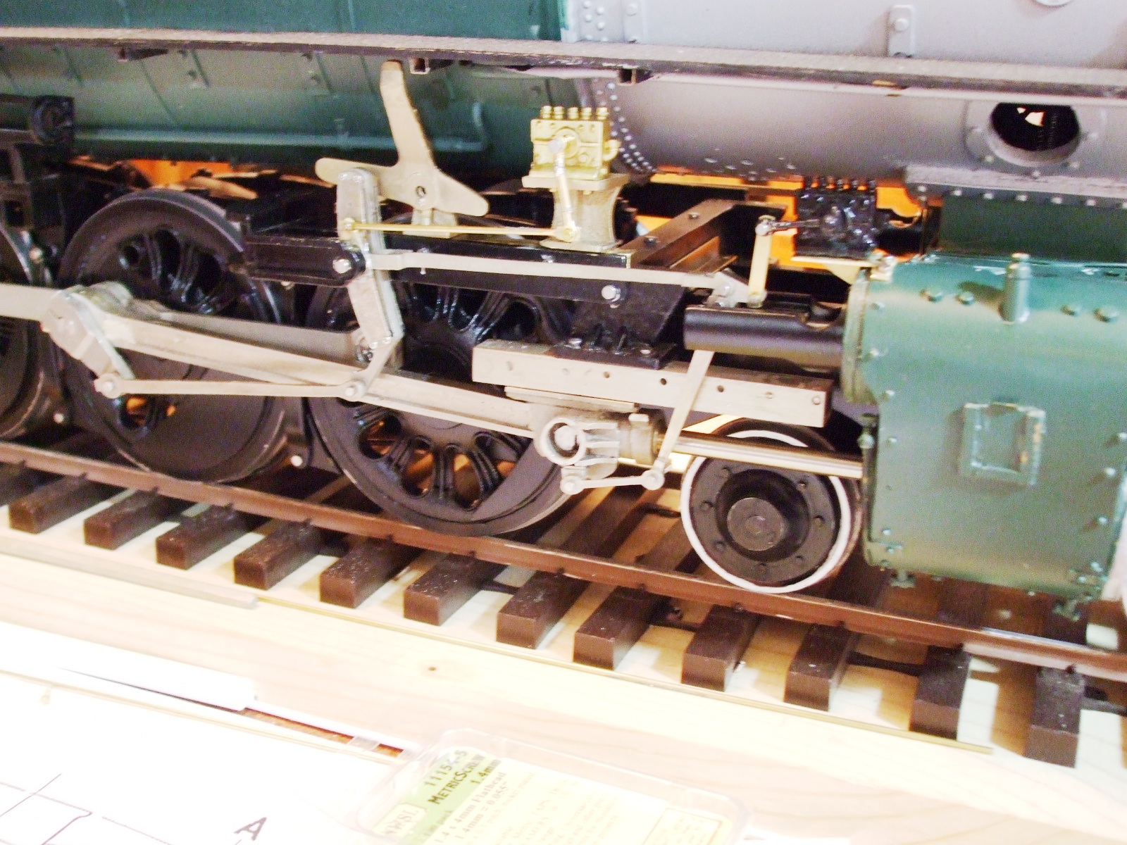
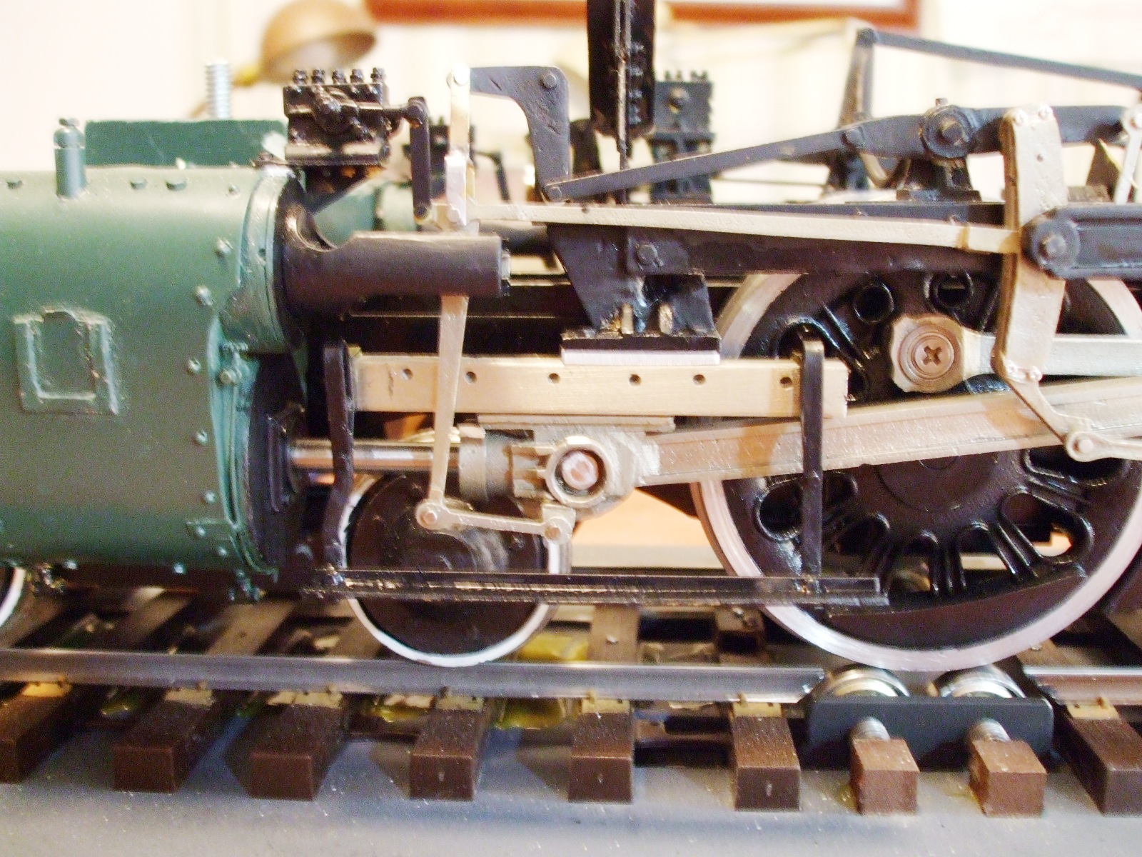
The Frame & Chassis
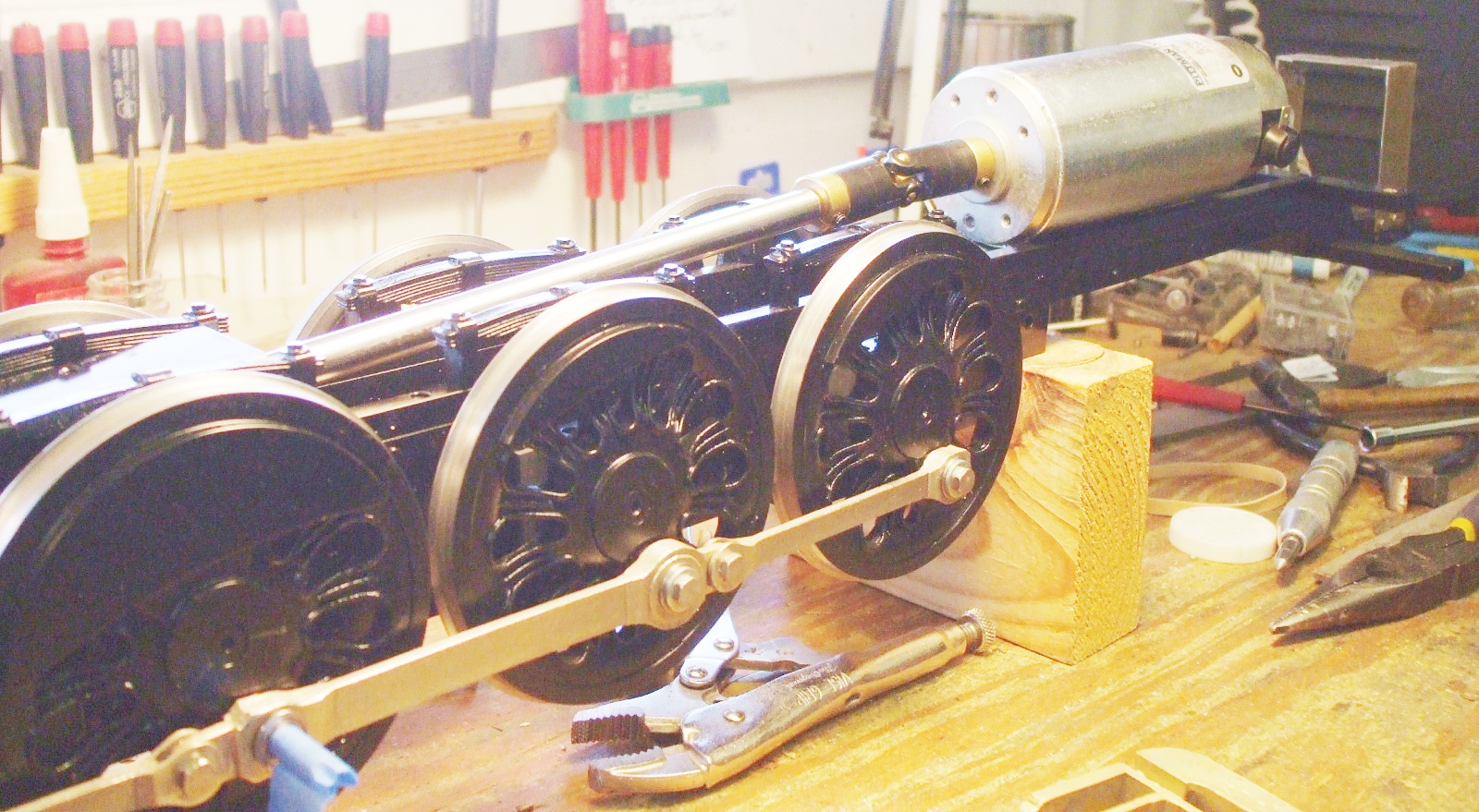
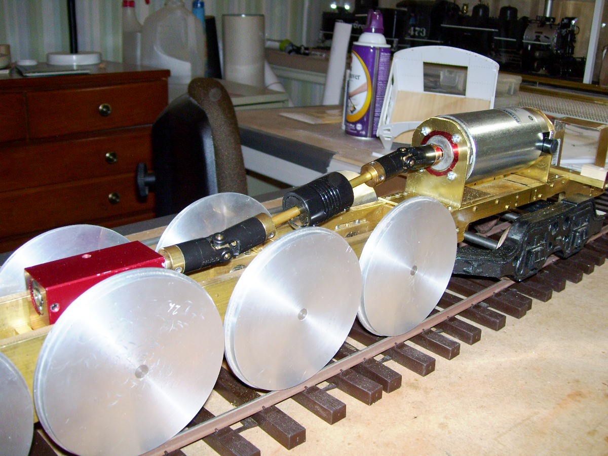
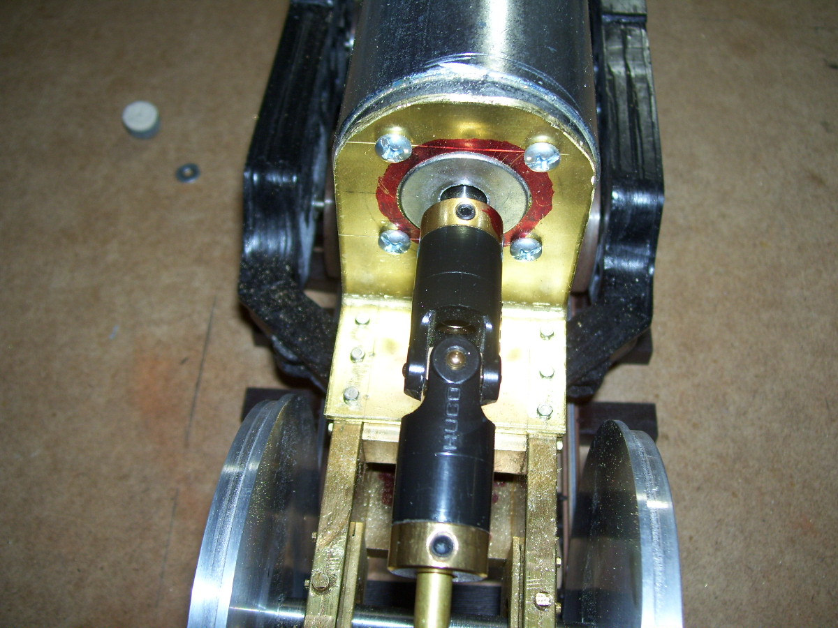
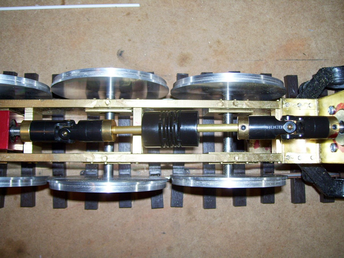
The Drive Train
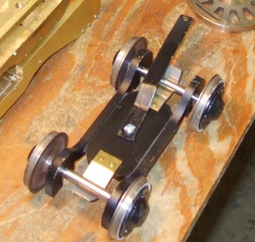
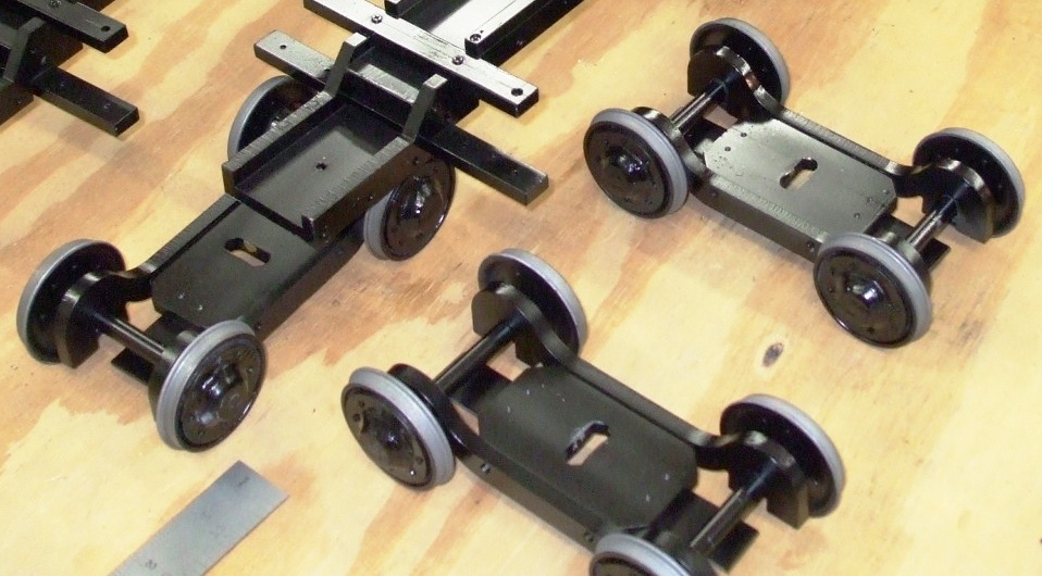
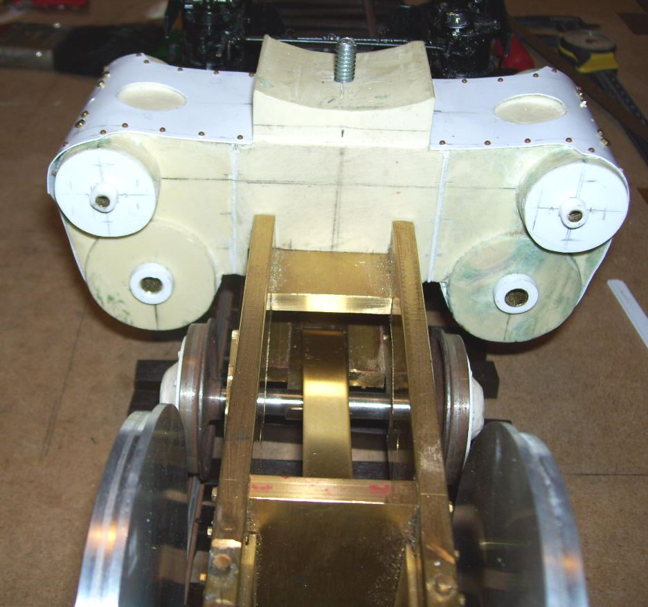
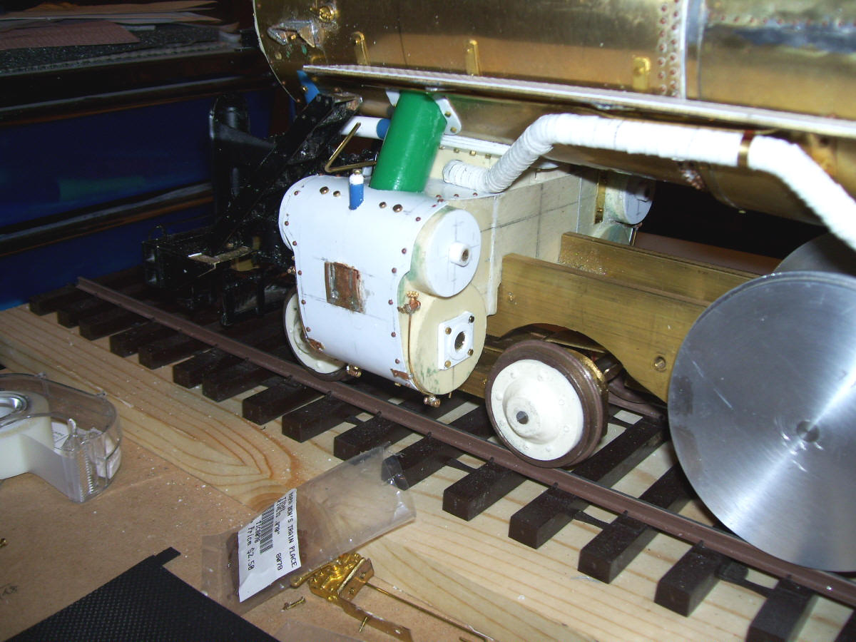
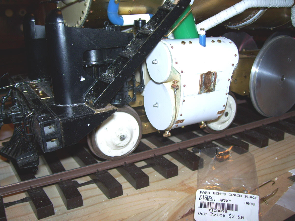
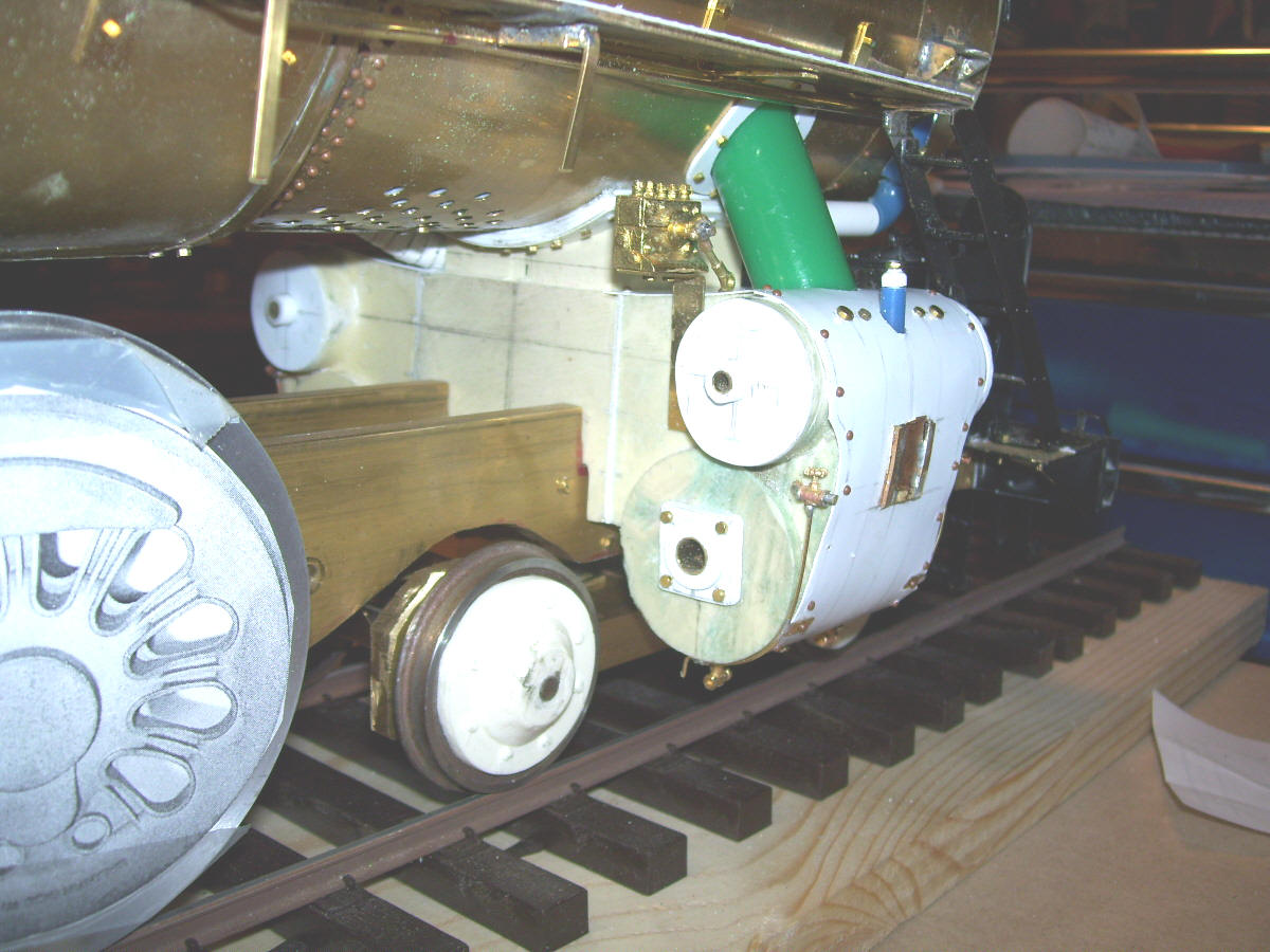
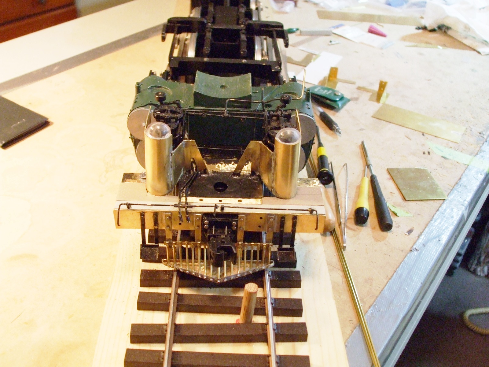
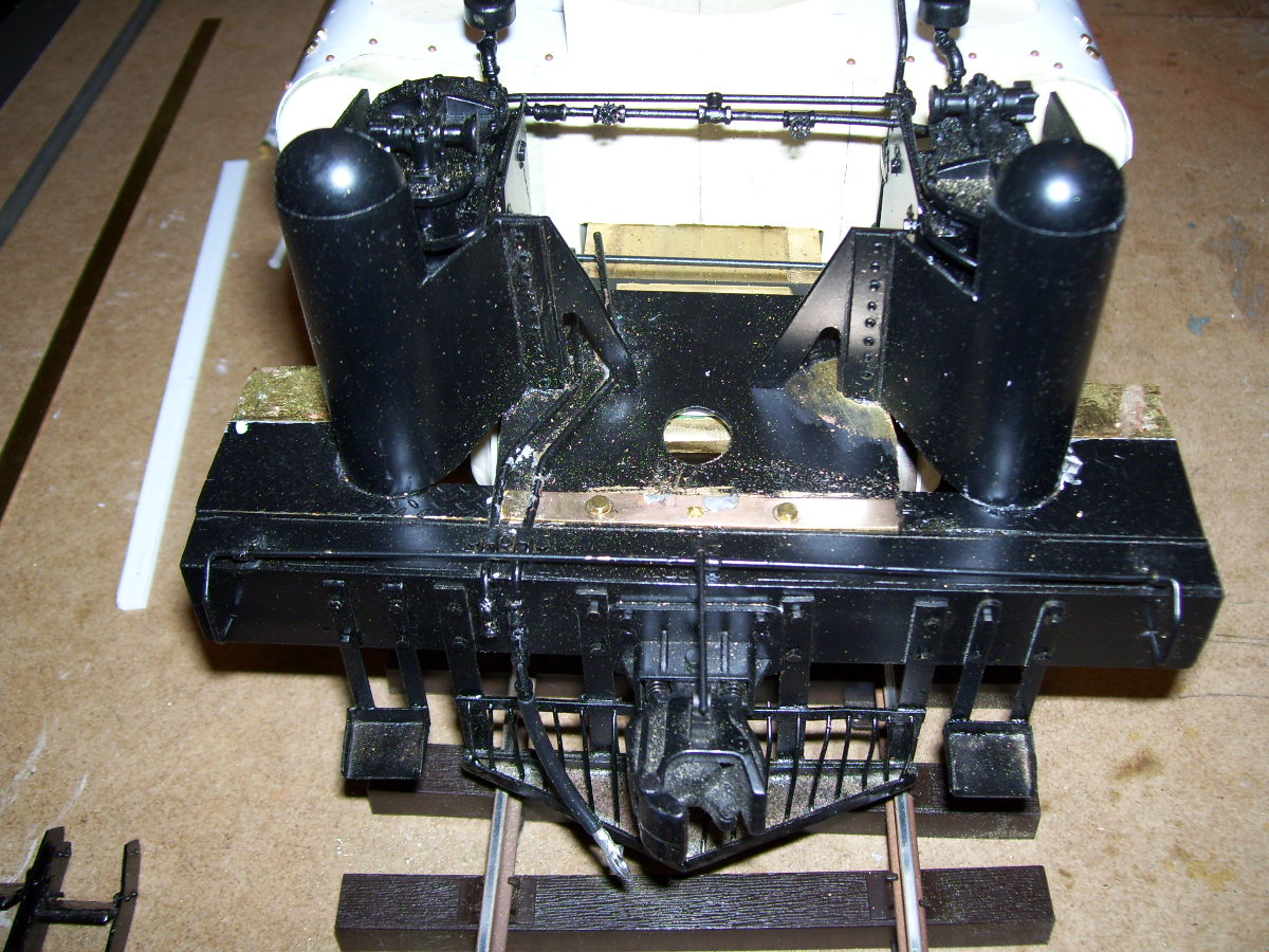
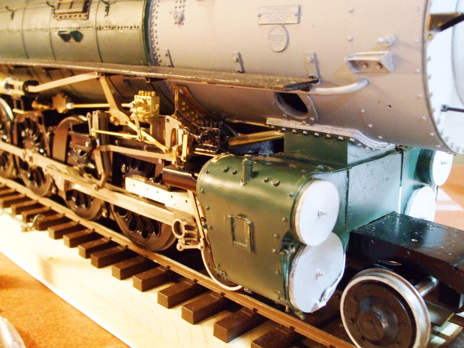
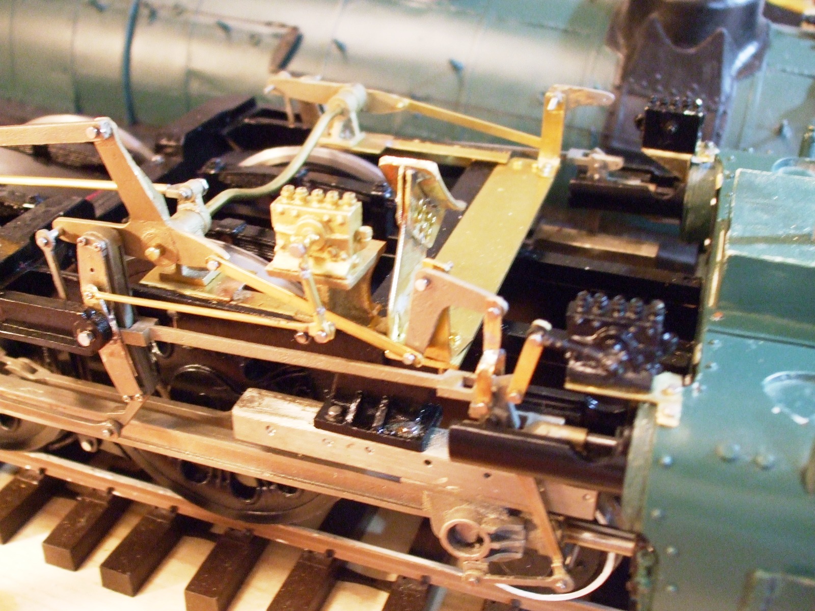
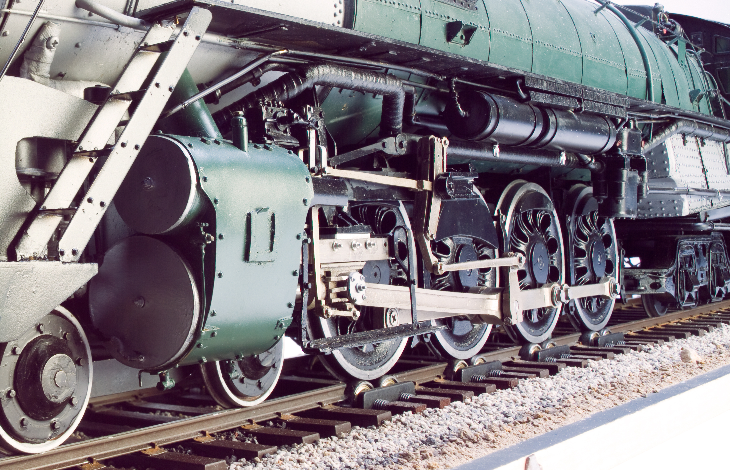
Cylinders, Lead & Trailing Truck
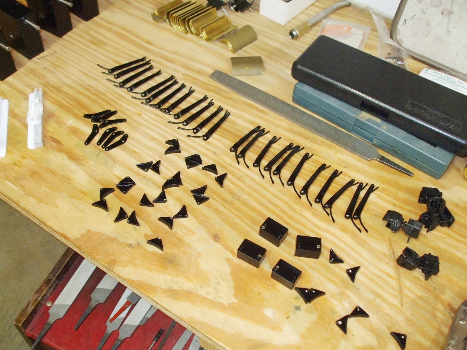
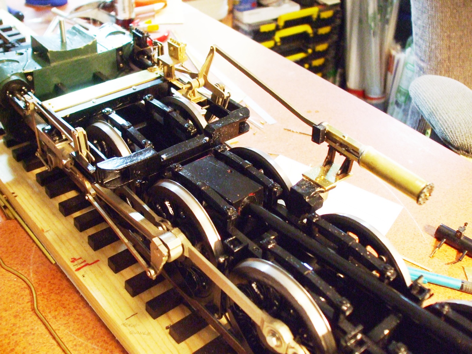
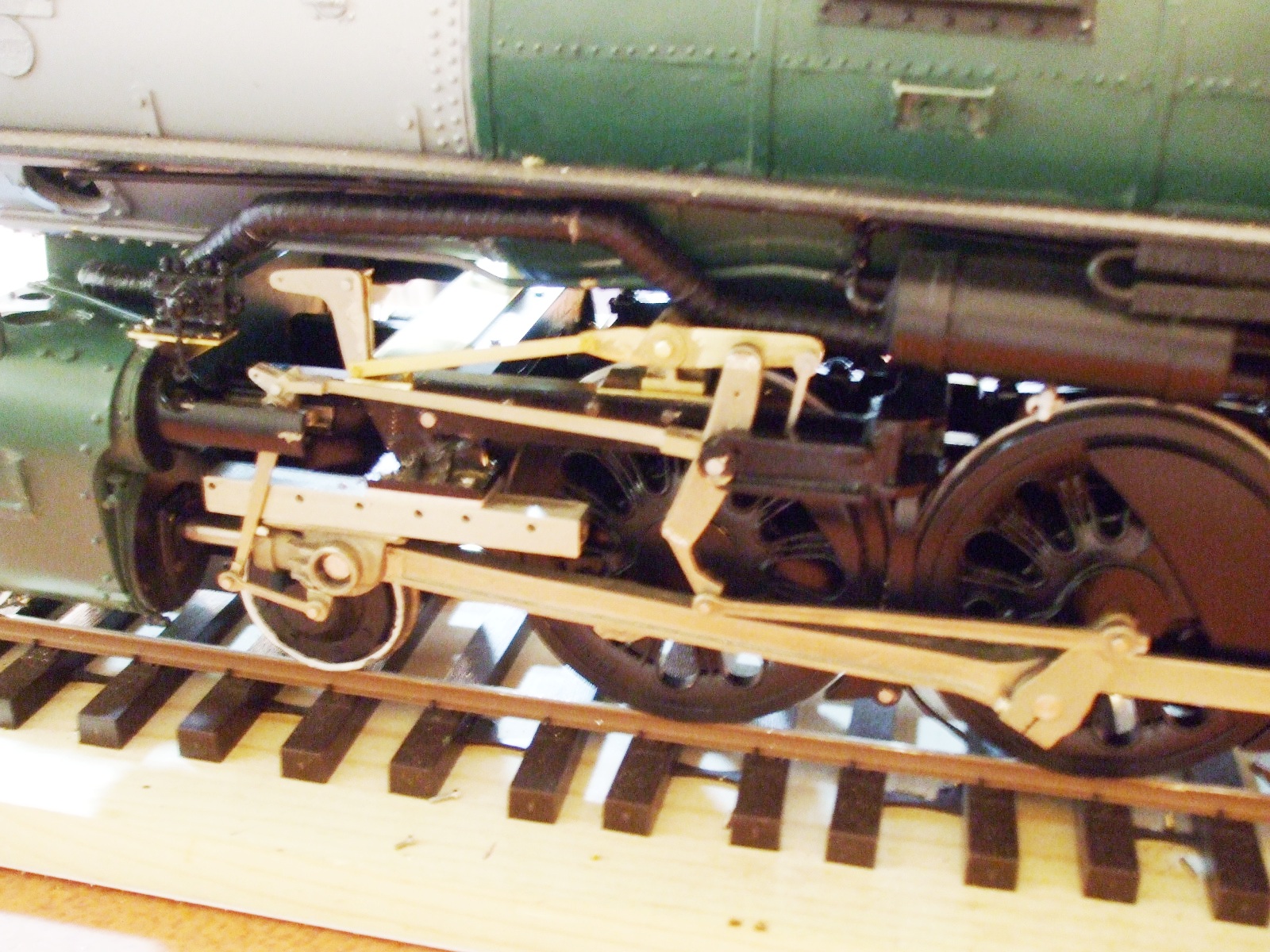
Valve Gear, Hangars & Misc.
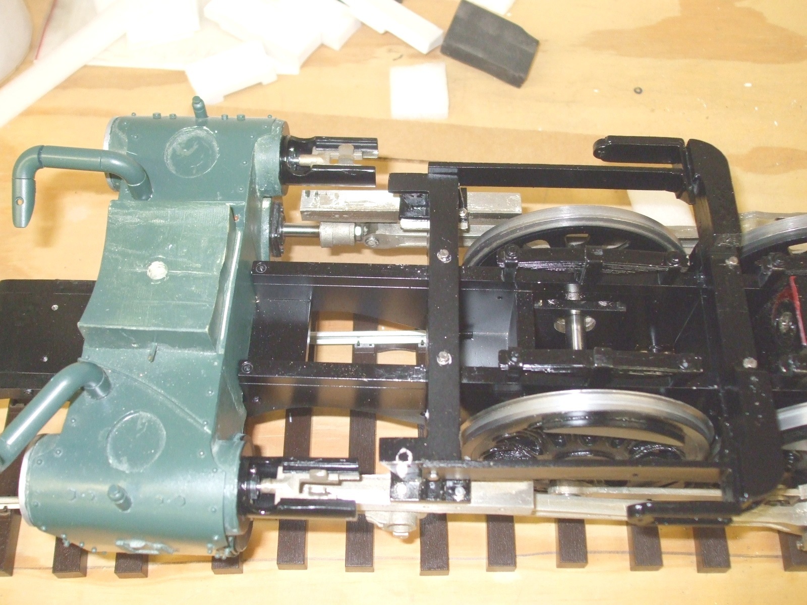
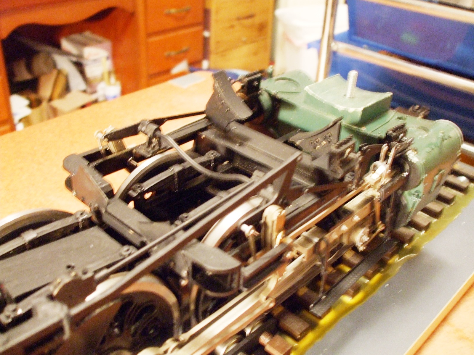
Suspension
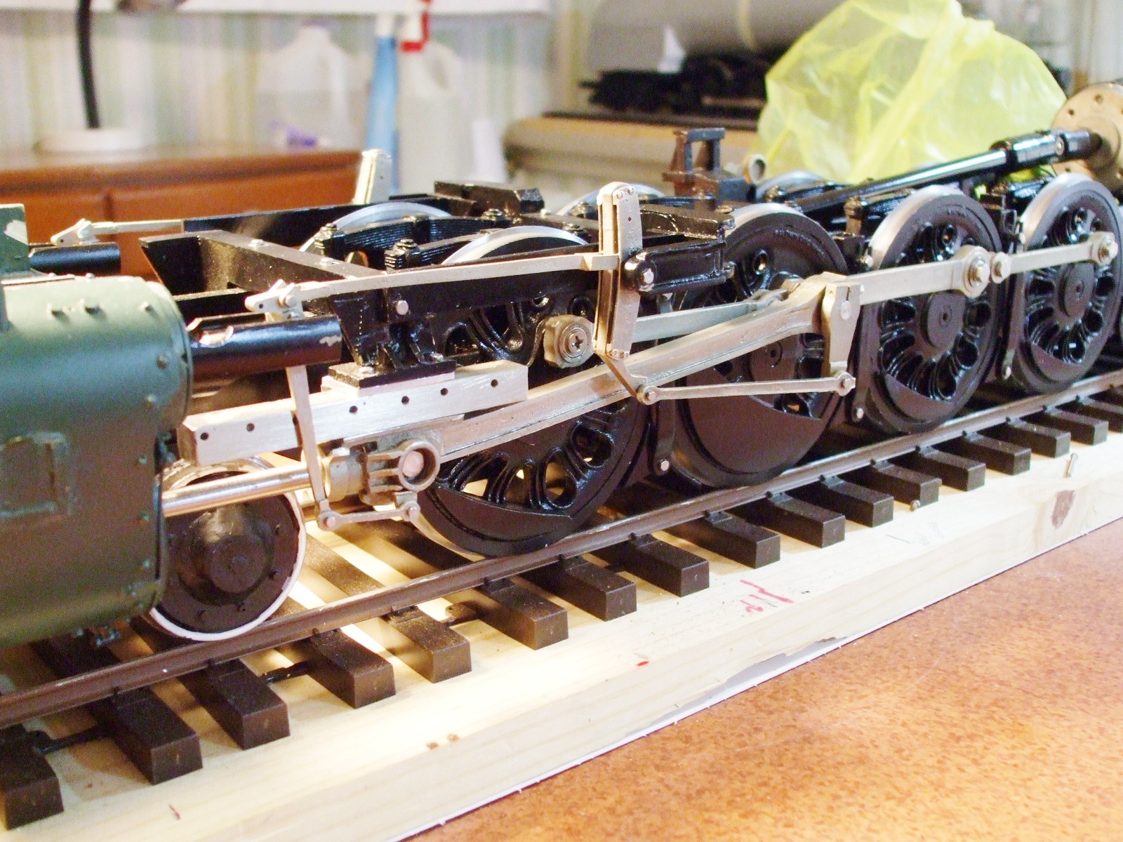
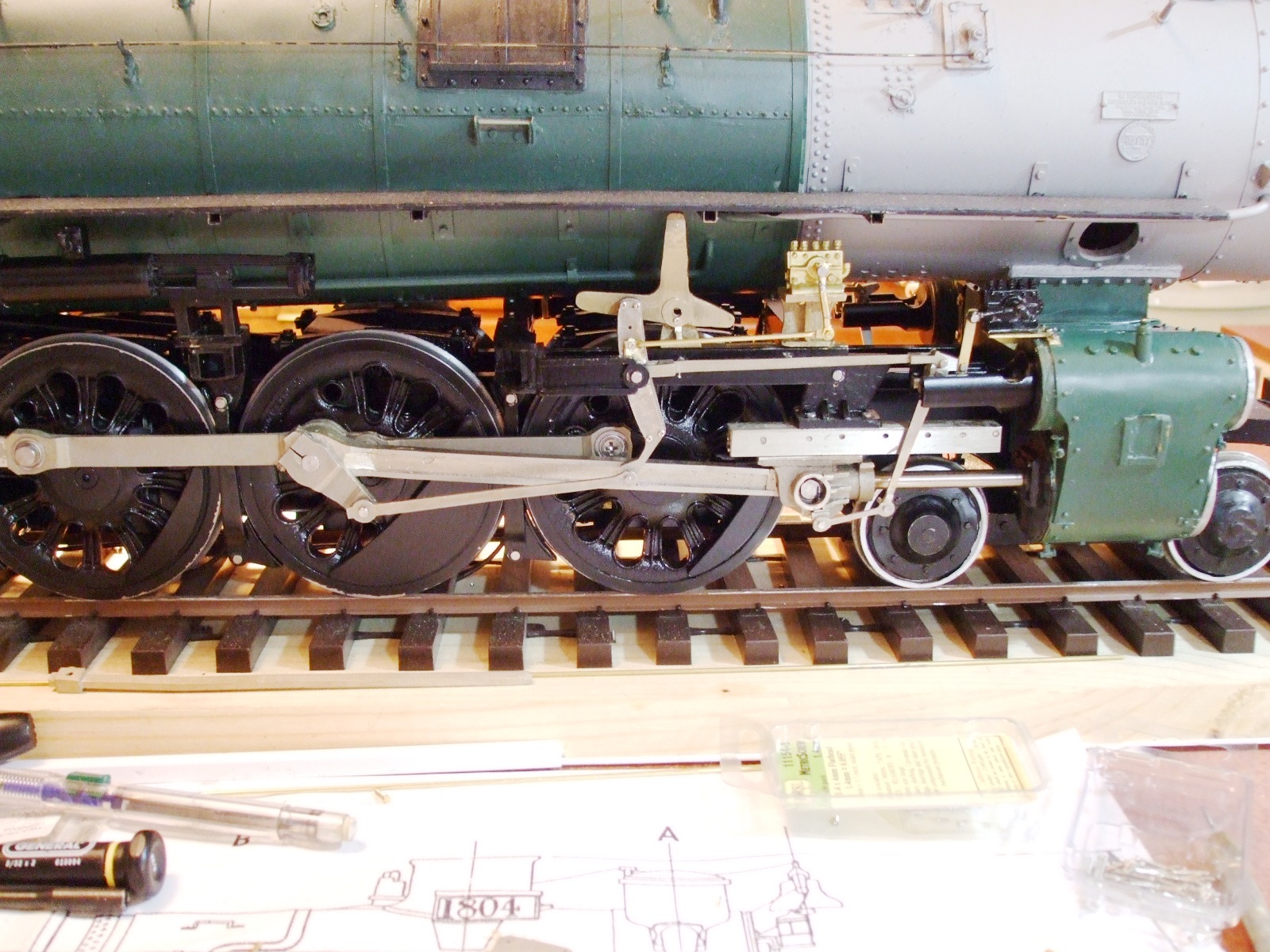
The Completed Chassis
|
|
|
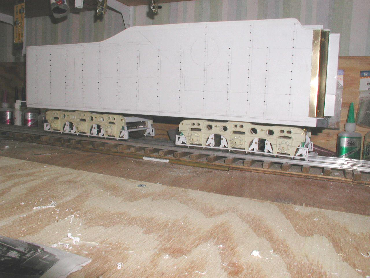
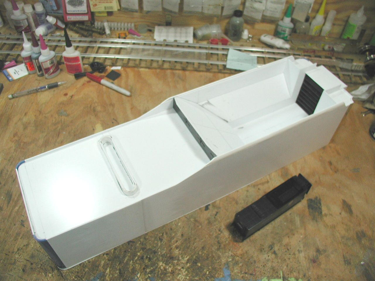
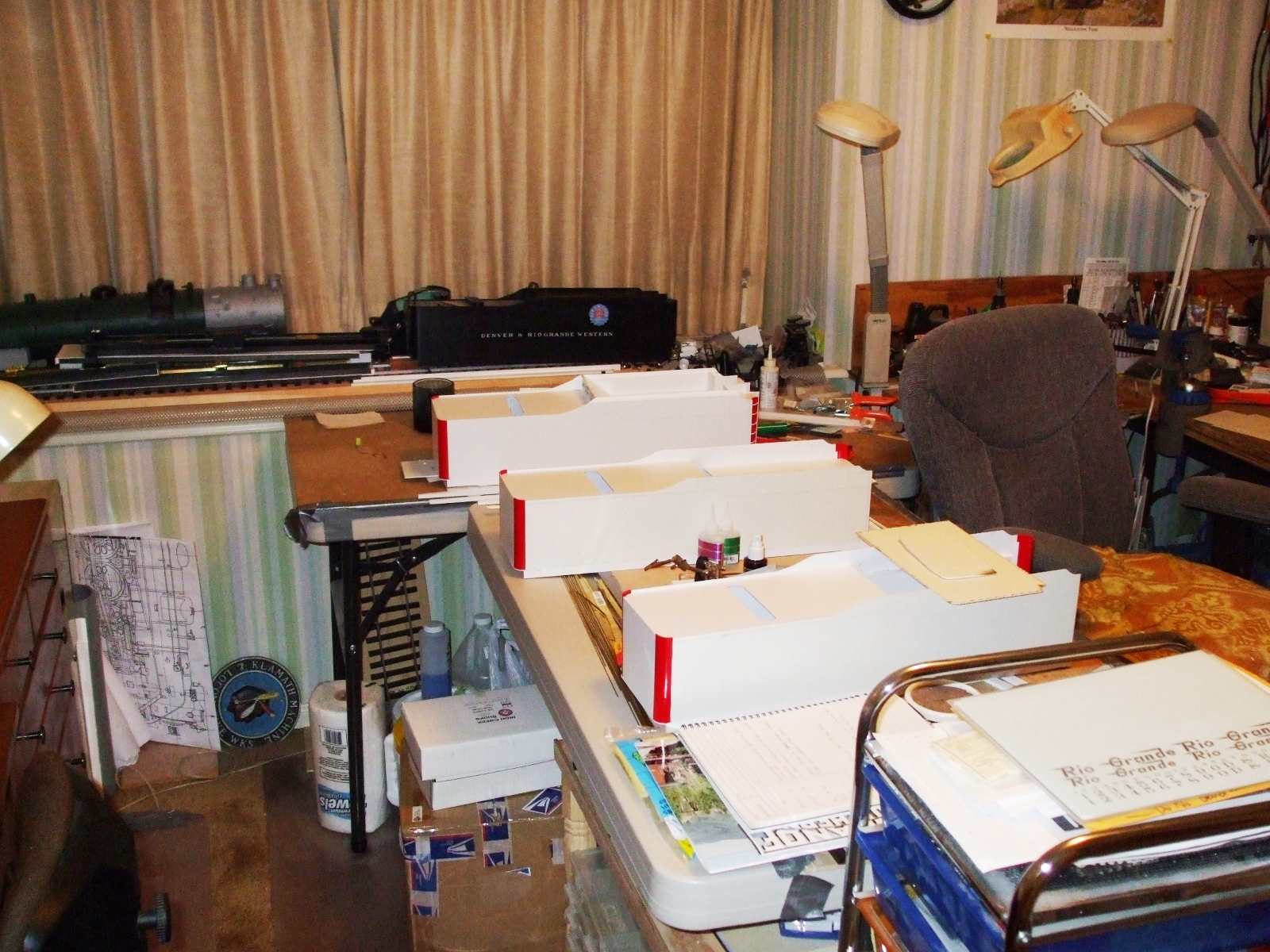
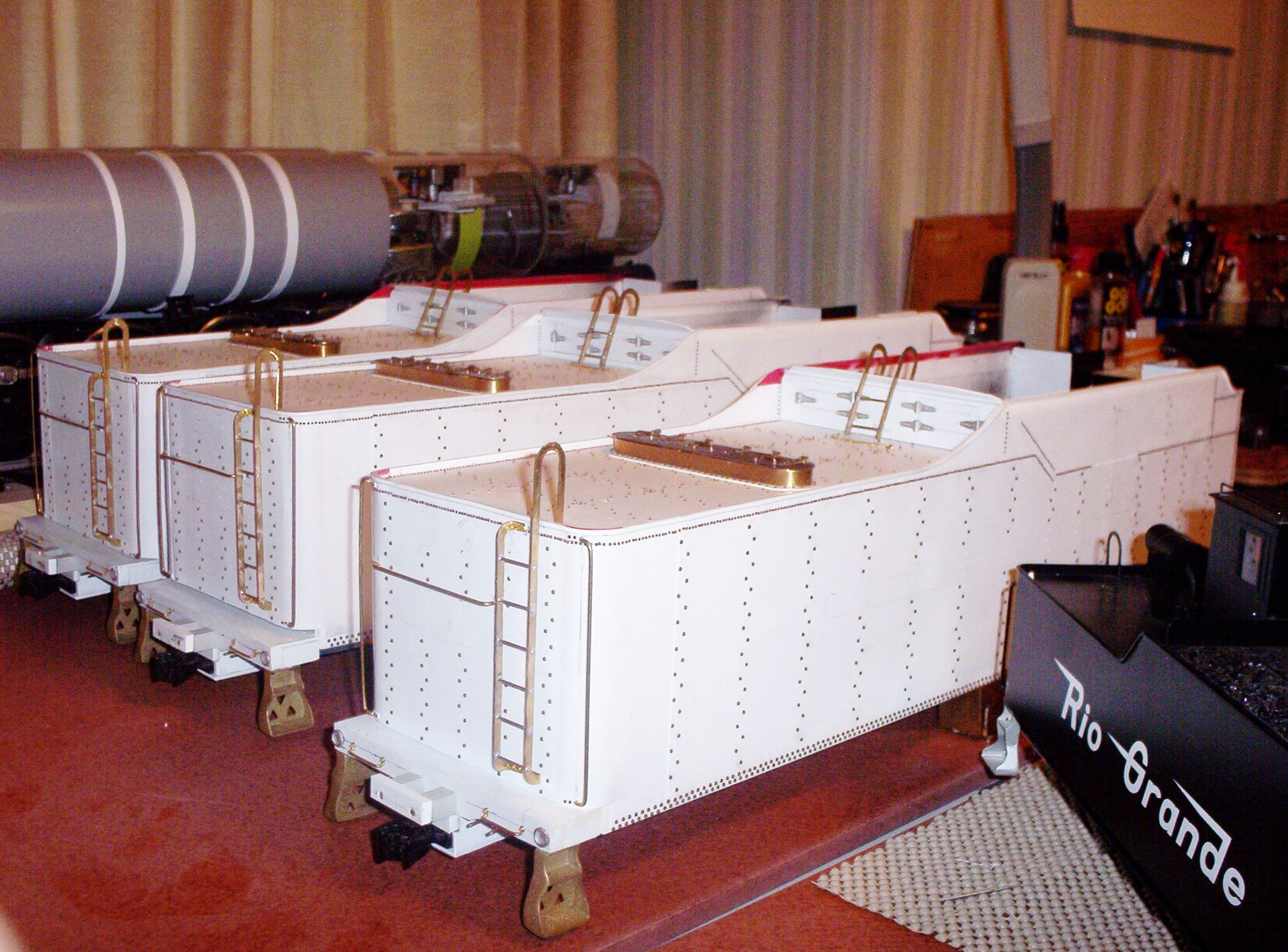
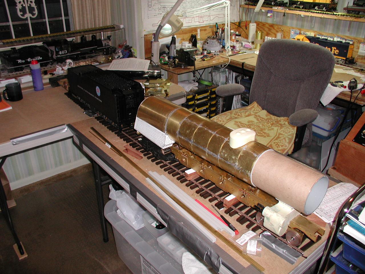
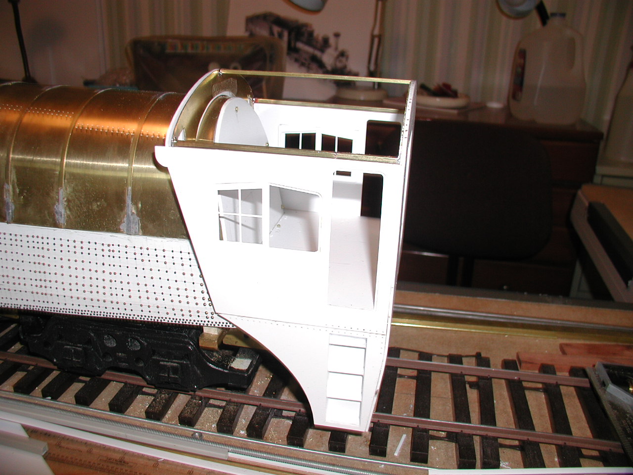
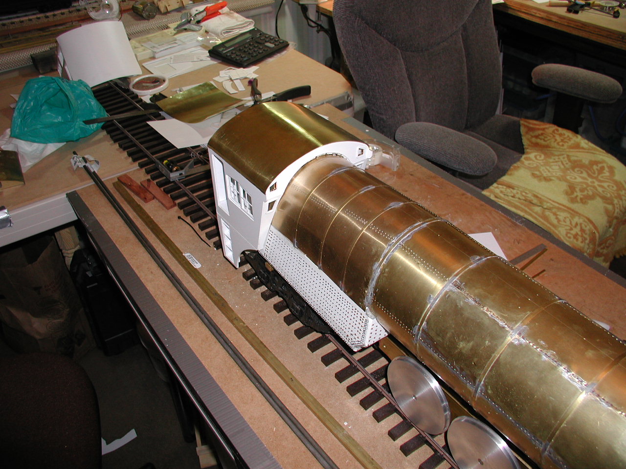
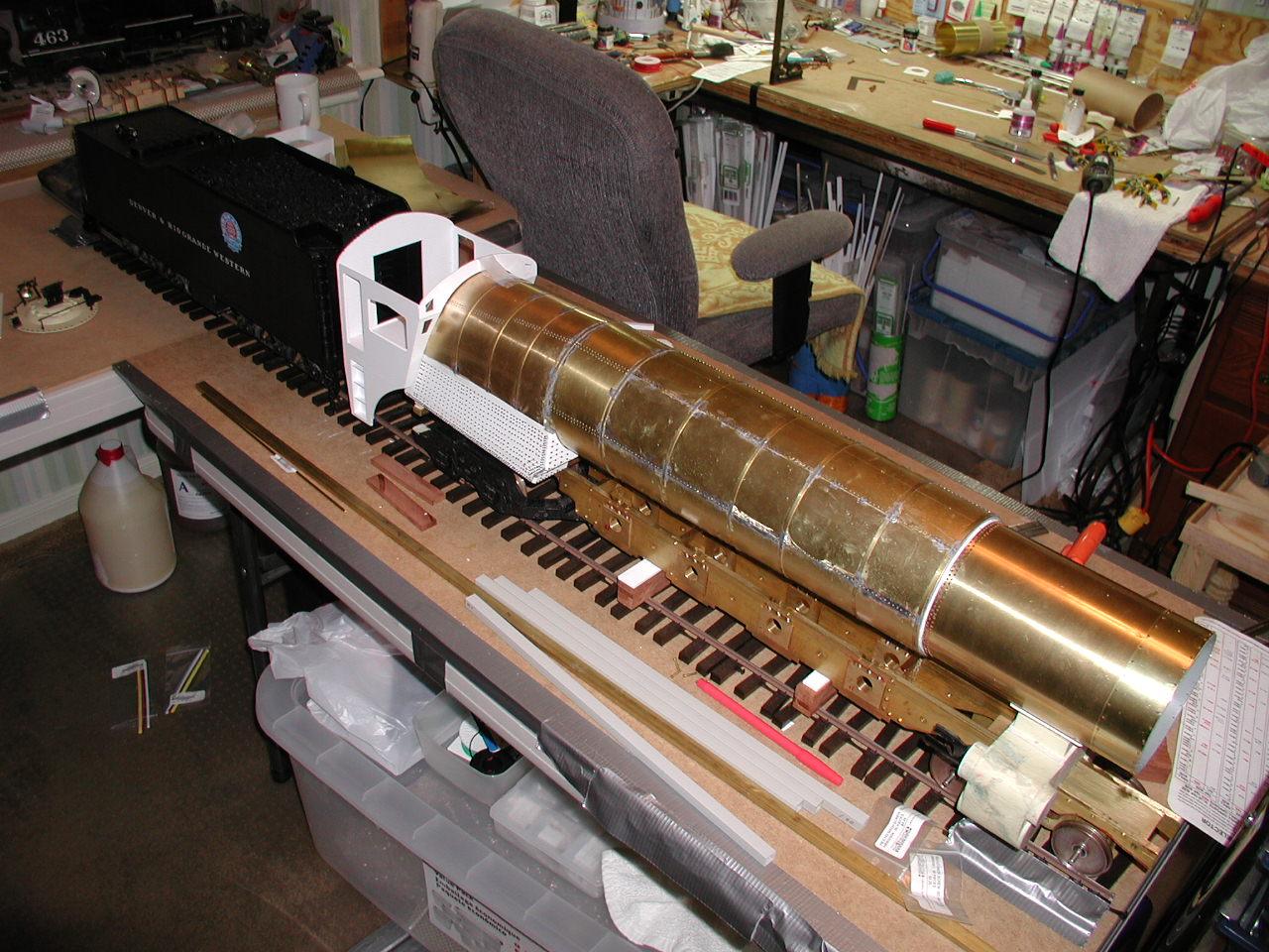
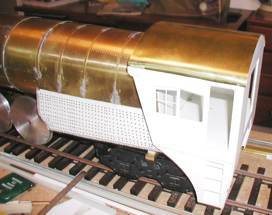
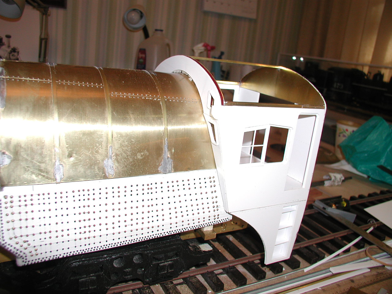
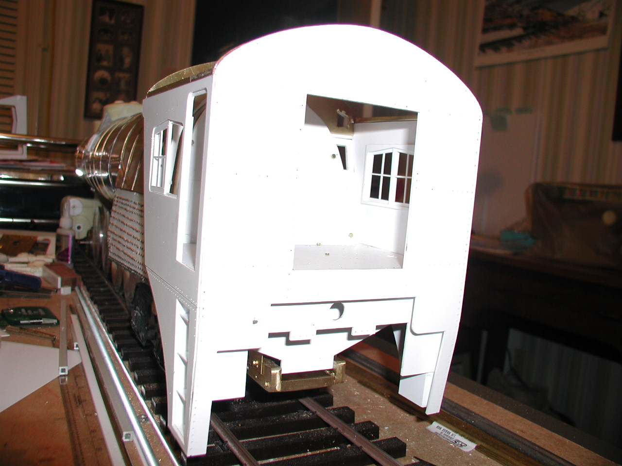
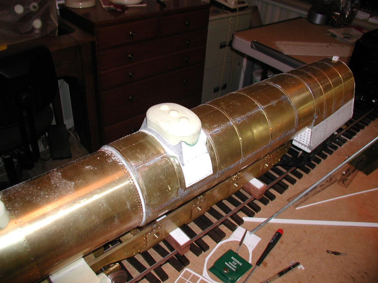
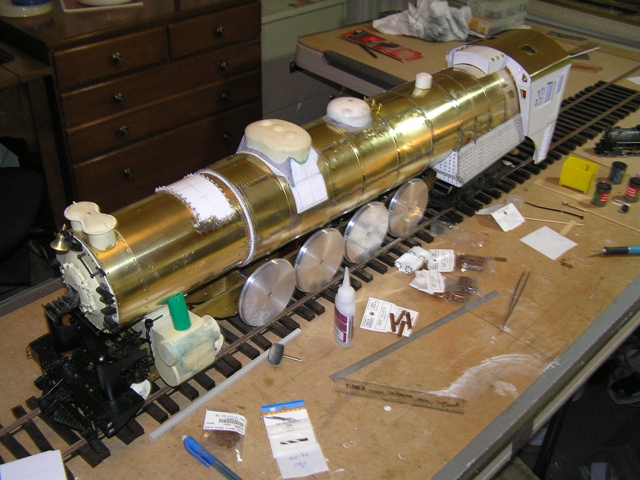
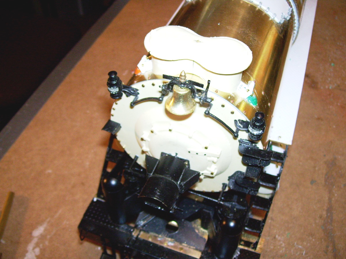
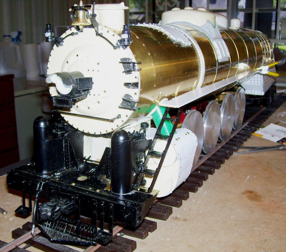
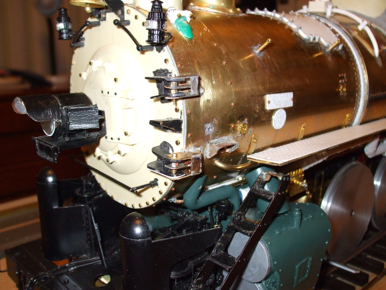
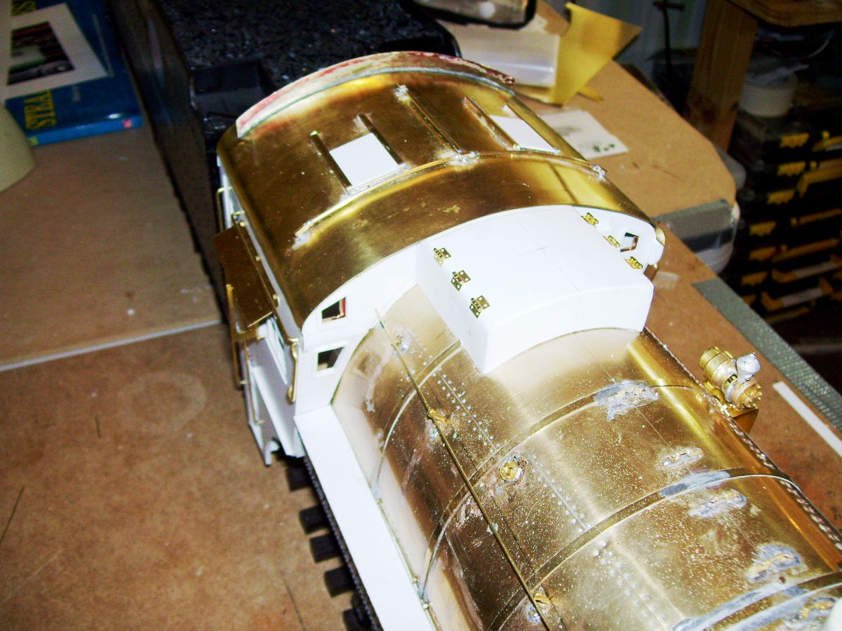
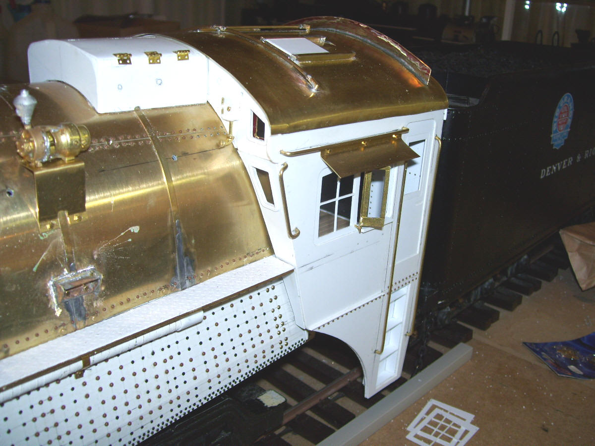
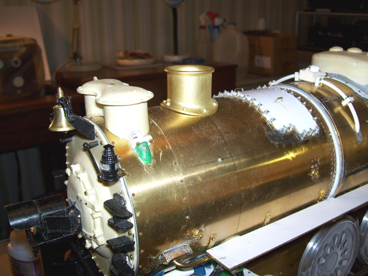
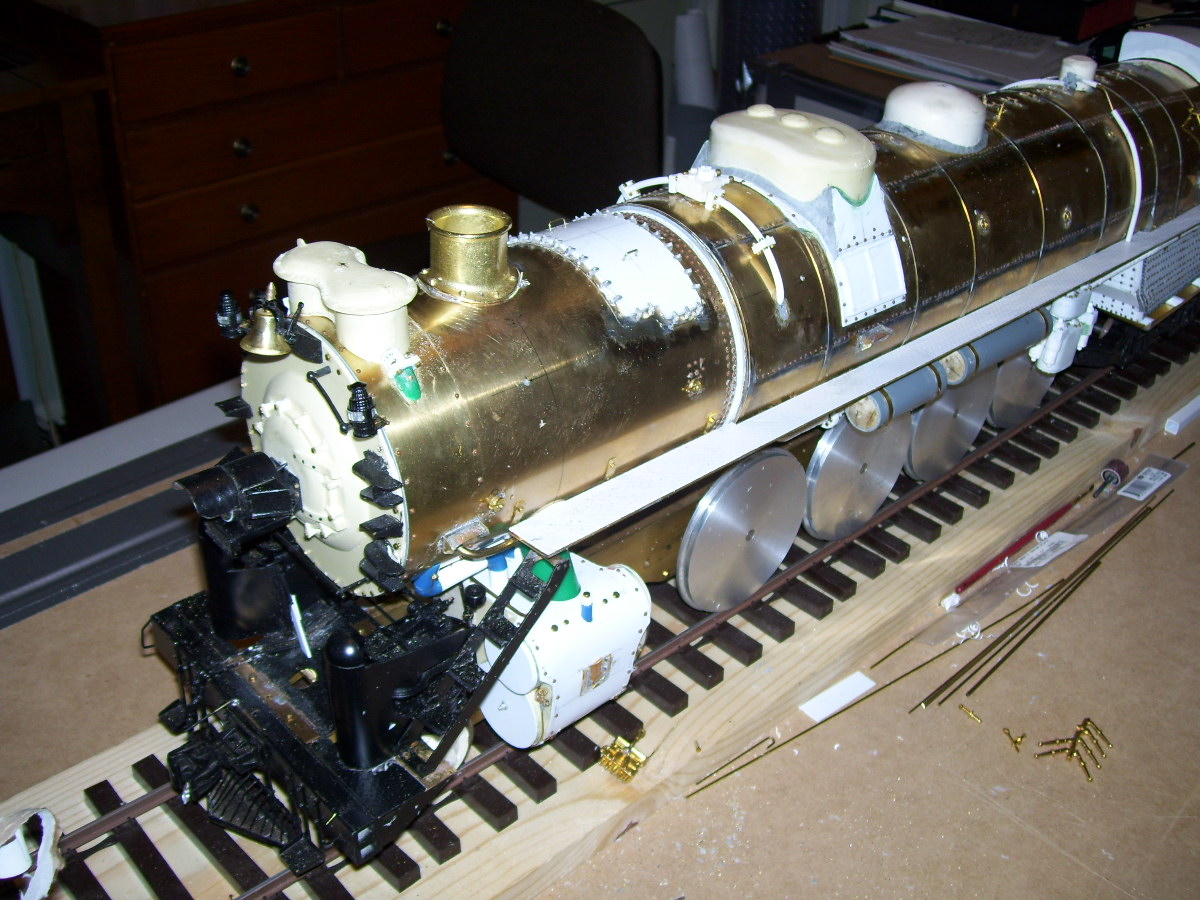
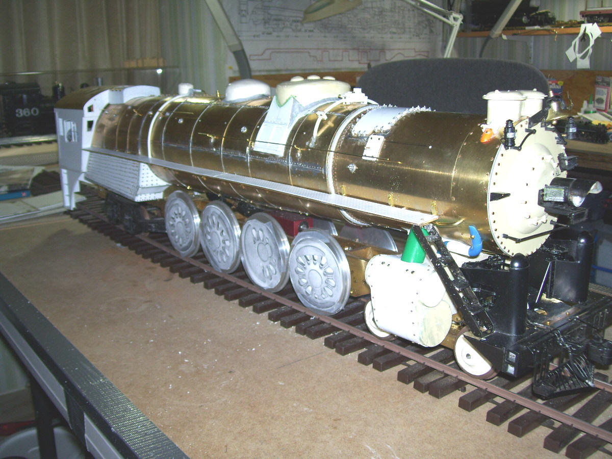
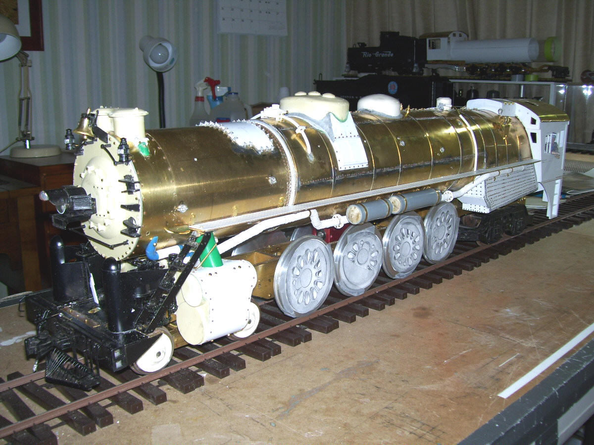
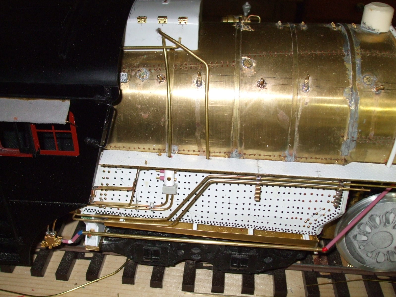
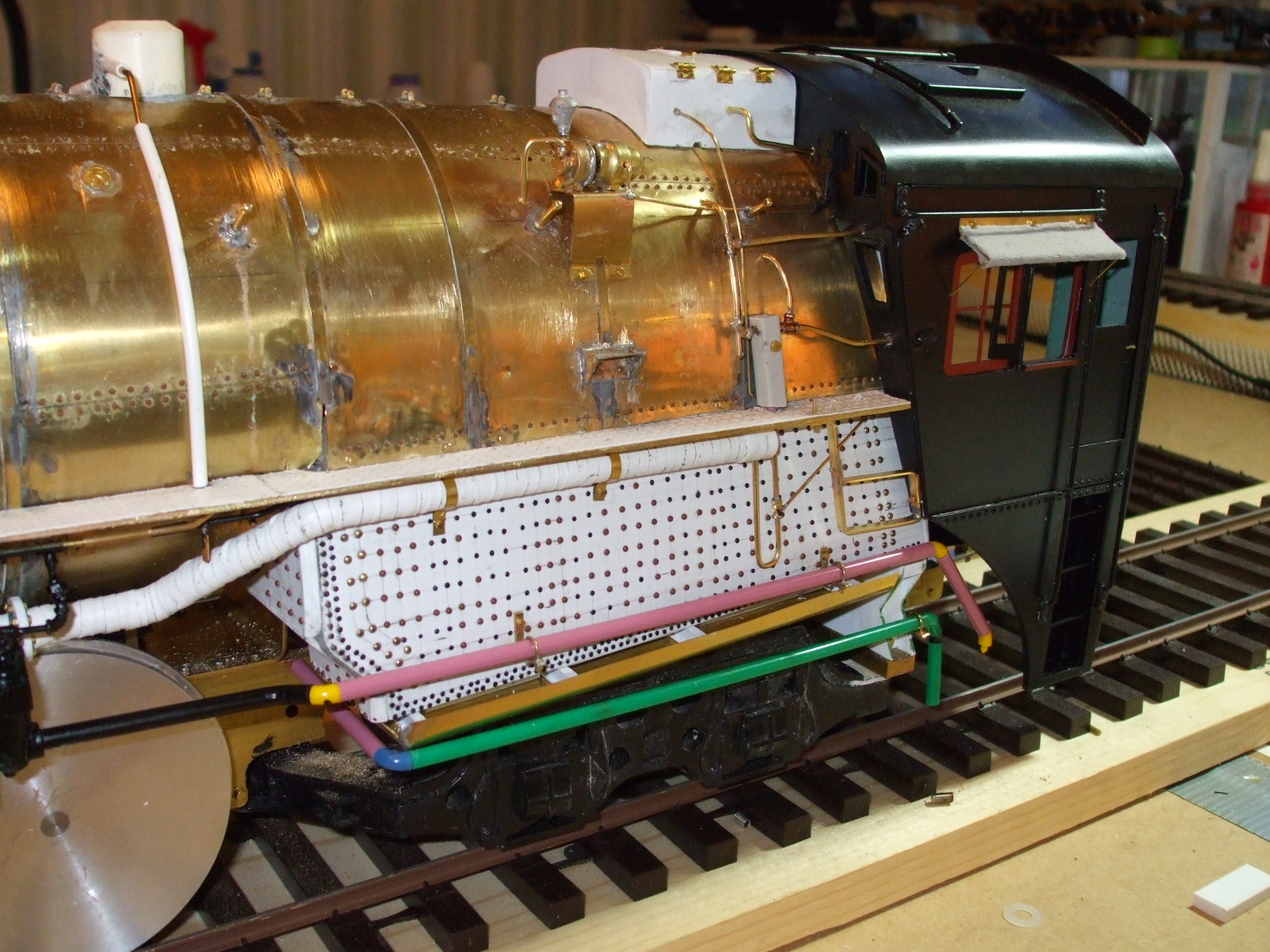
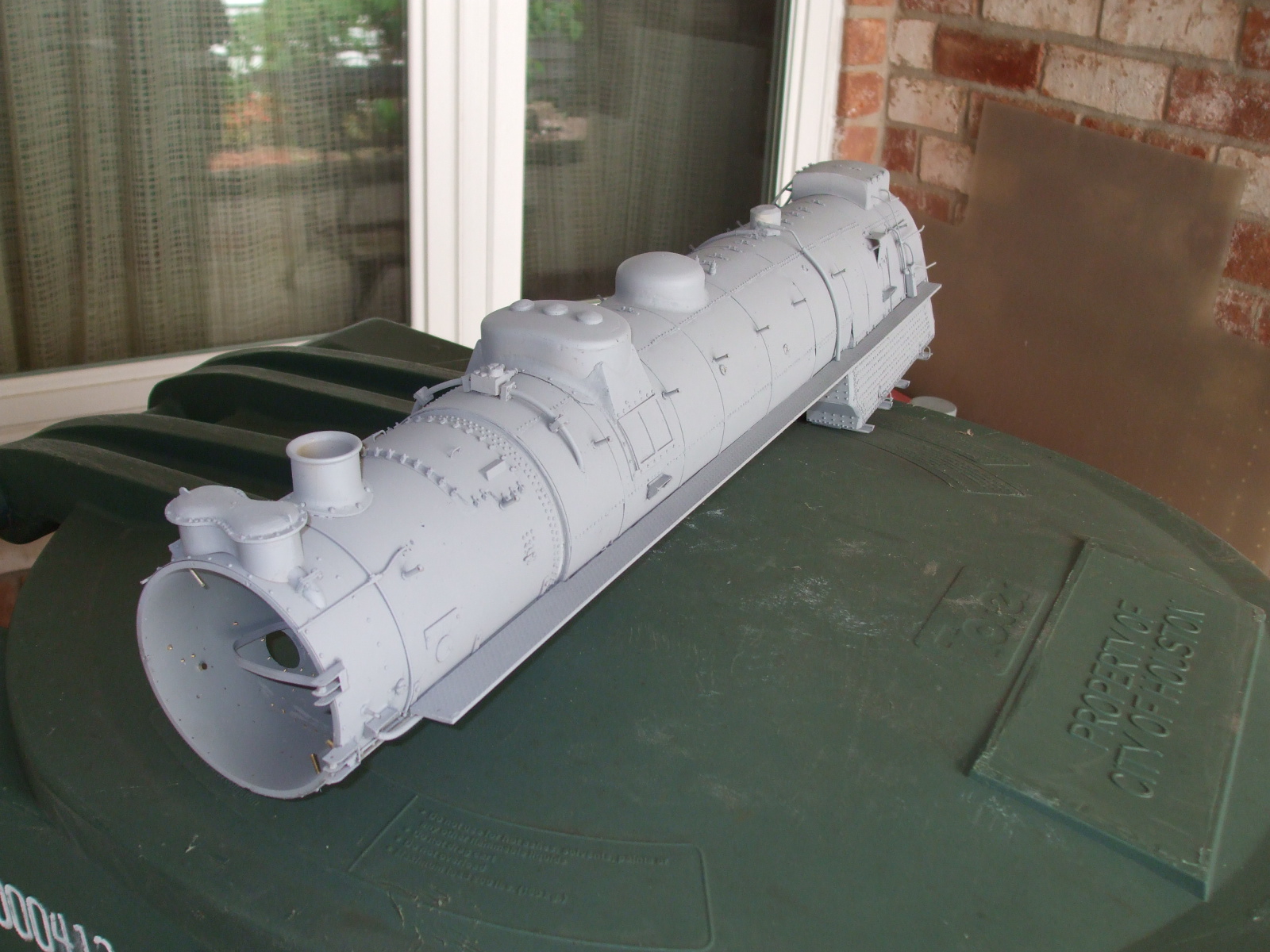
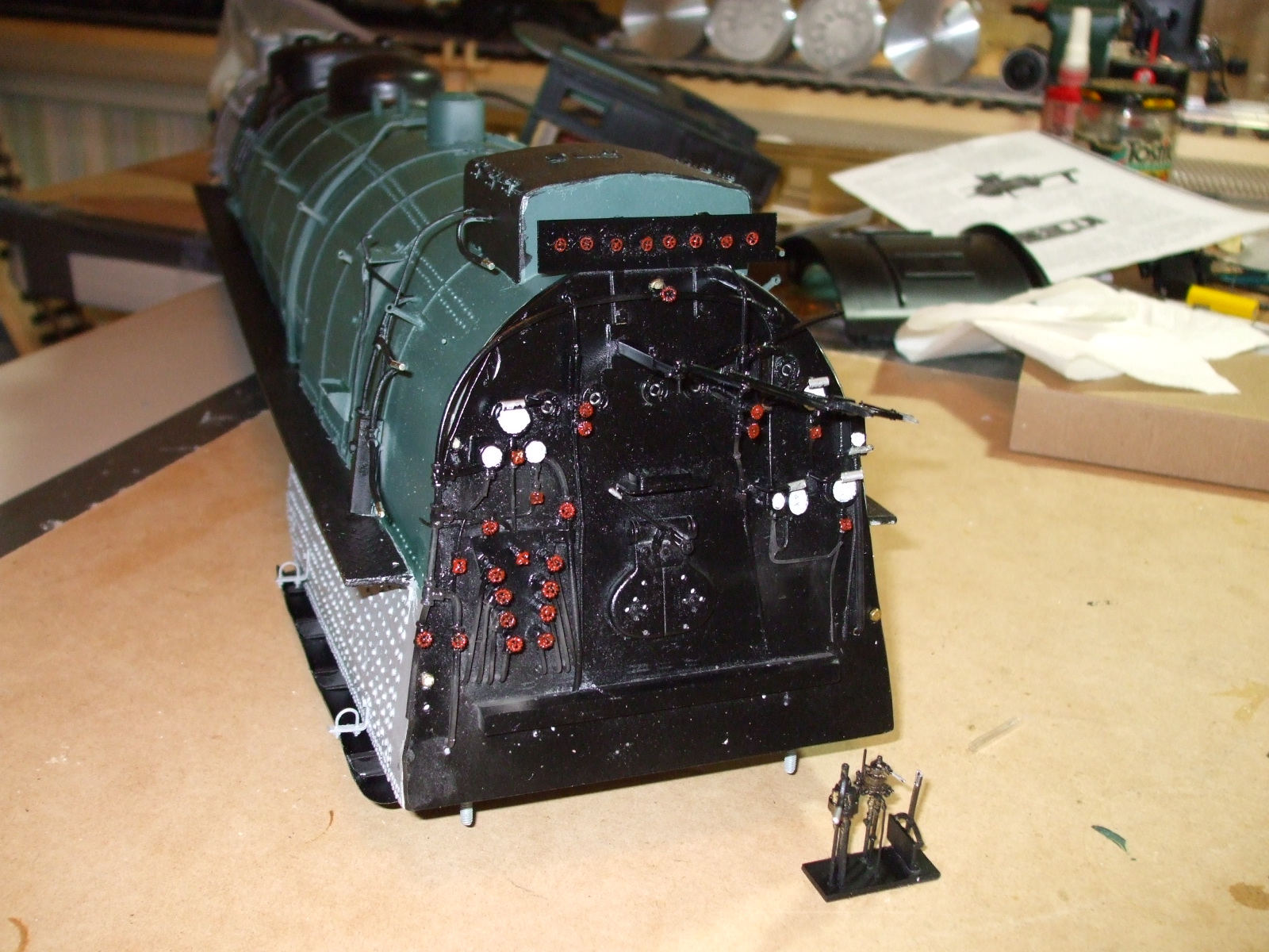
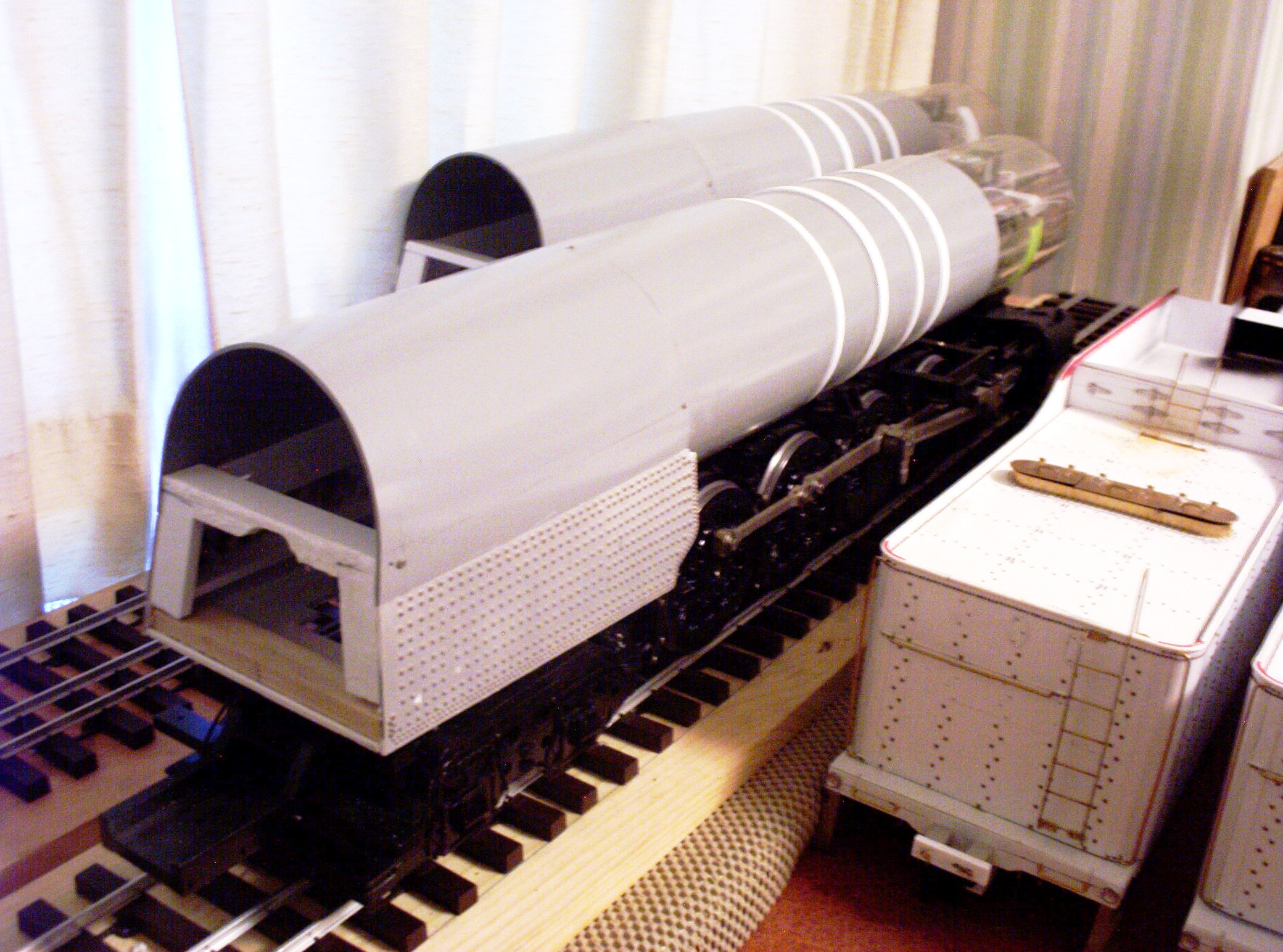
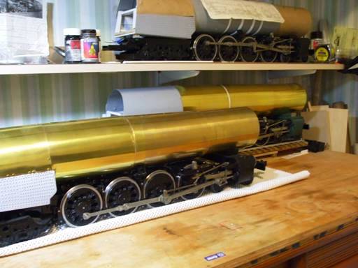
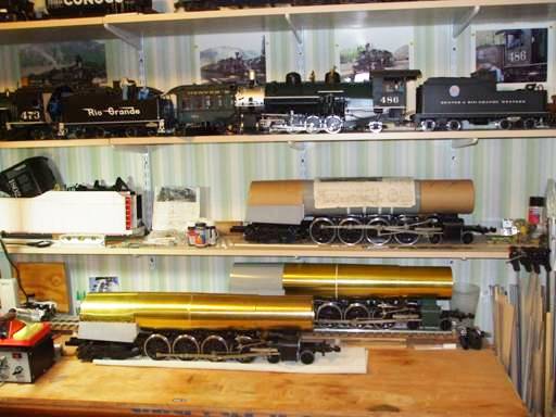
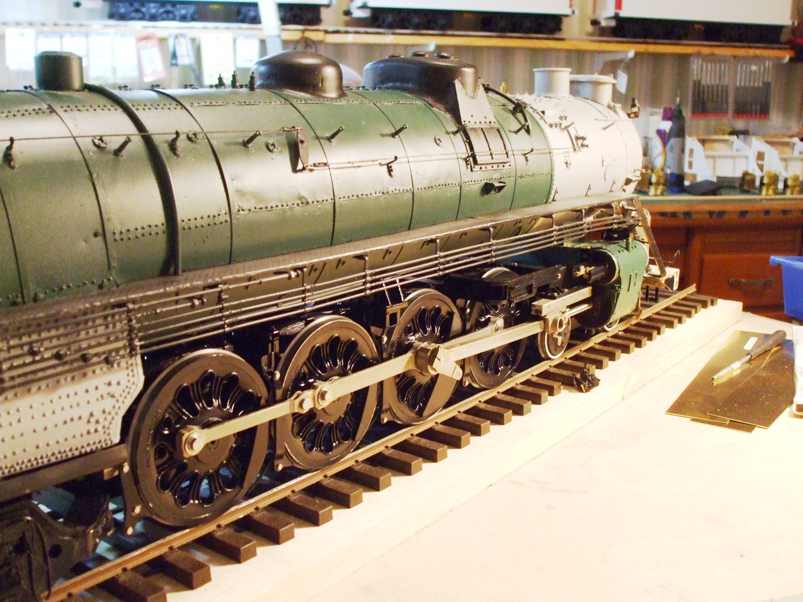
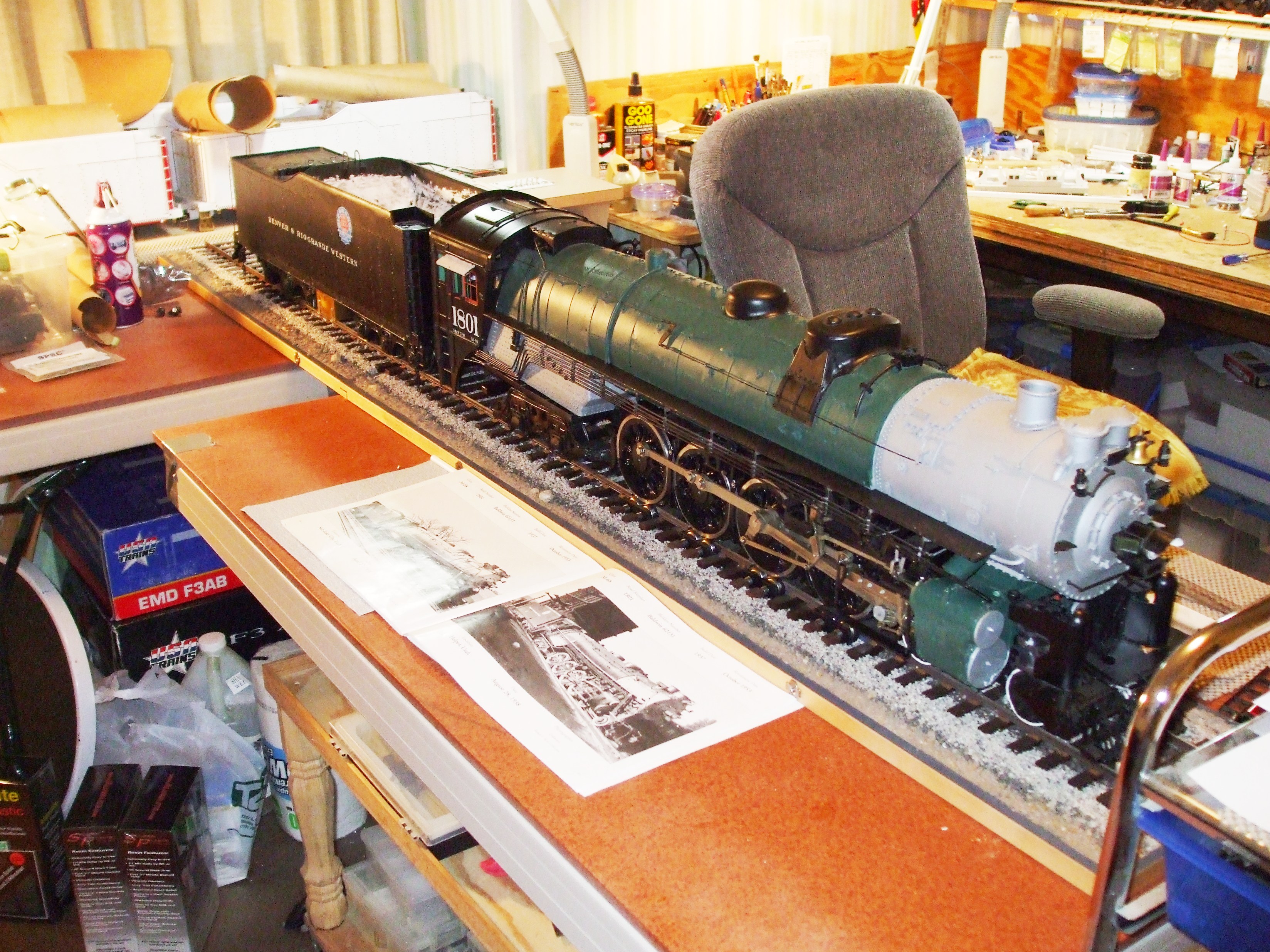
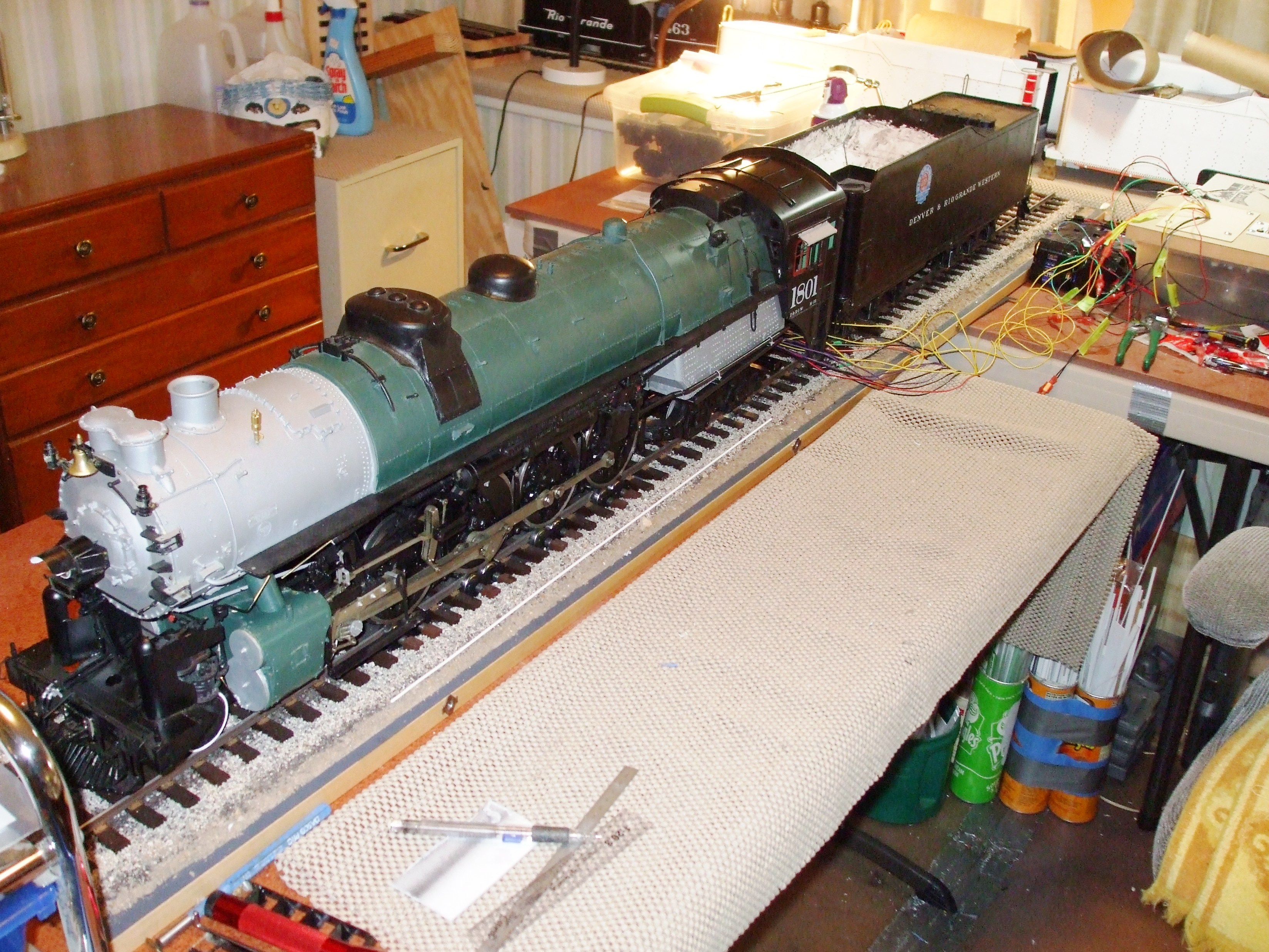
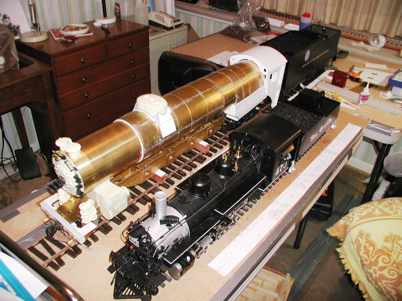
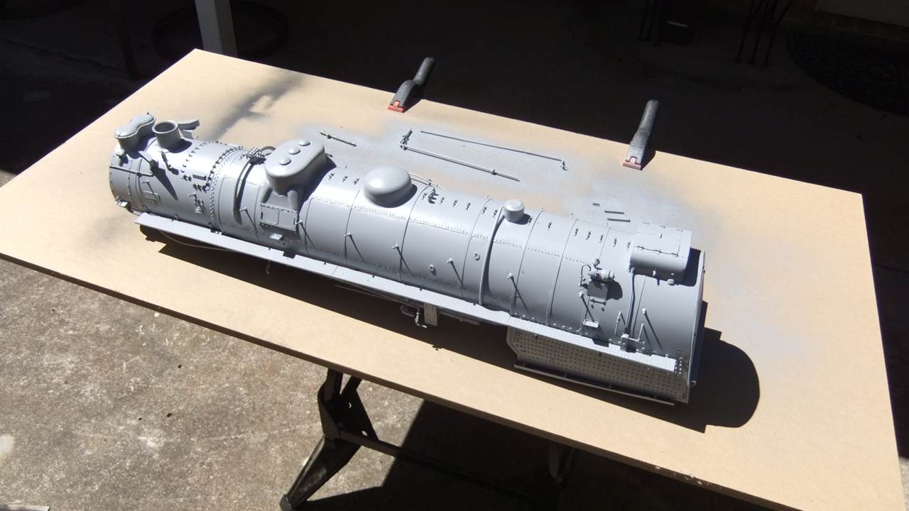
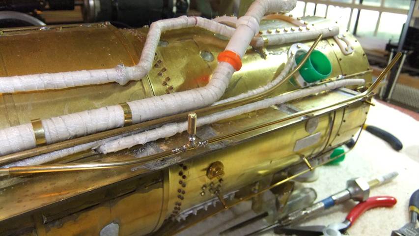
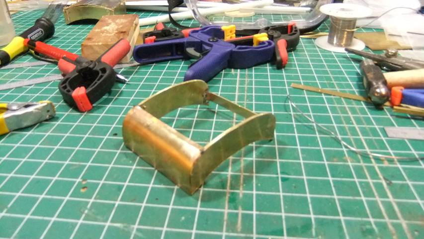
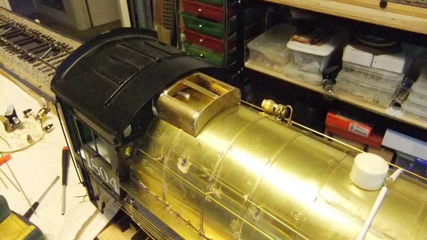
Boiler & Cab The oiler and cab on Doug's locomotives are made from a combination of ABS tube, overlaid with a thin sheet of brass embossed with rivet detail where appropriate, various styrene shapes to made up the cab and firebox sides, and then urethane castings for the domes. The stack is a brass investment casting made by Bill Brisko and cast by Trackside Details. What appears to be a cardboard mock-up of the boiler is actually an overlay for a brass wrapper which surrounds the inner acrylic tube. Each rivet is a Tichy Train Group plastic rivet, about 500 of which are in each boiler, with an additional 300 in the firebox. The bottom row of pictures in this section shows Doug's progress as of February 2008.
|
|
|
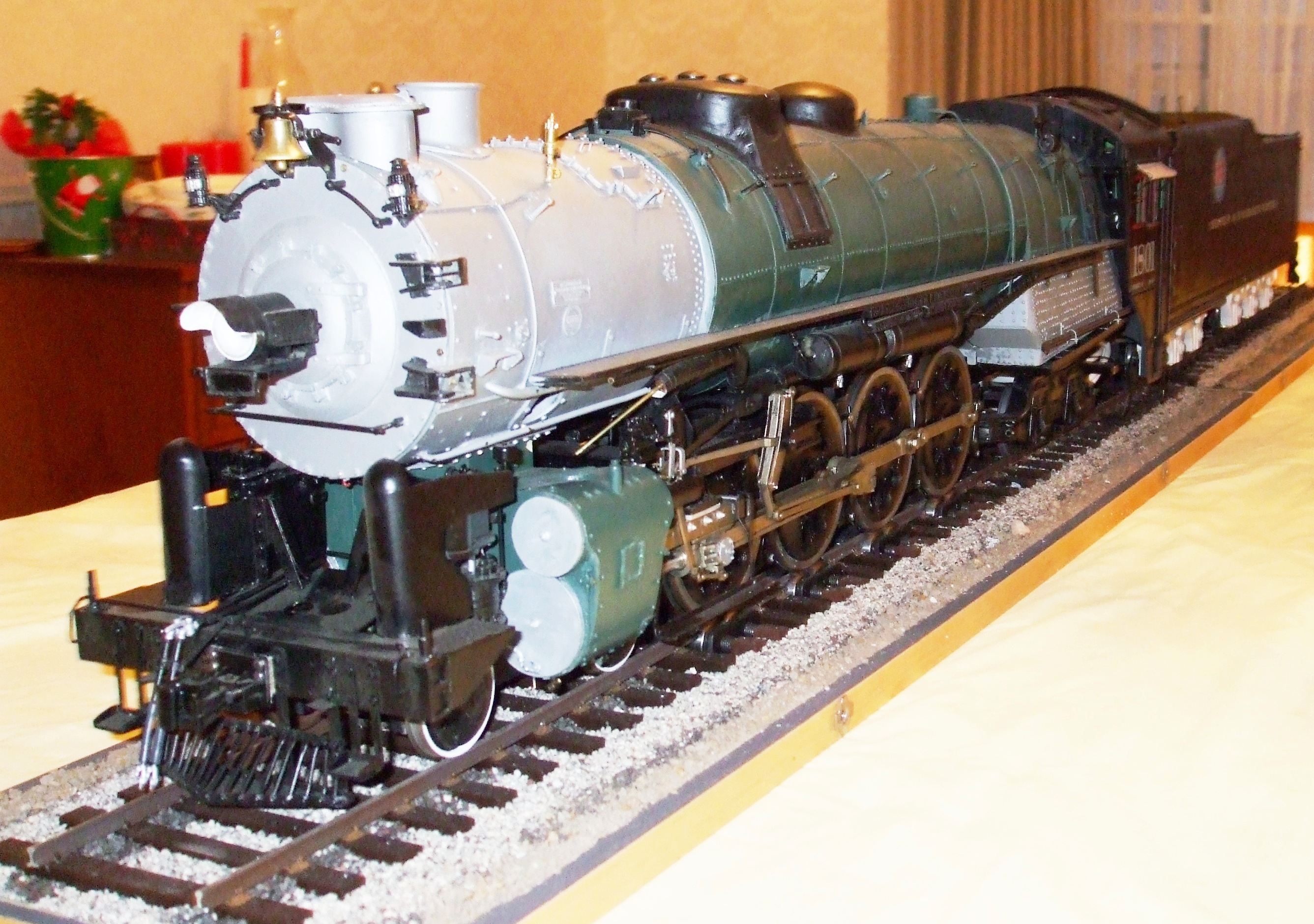
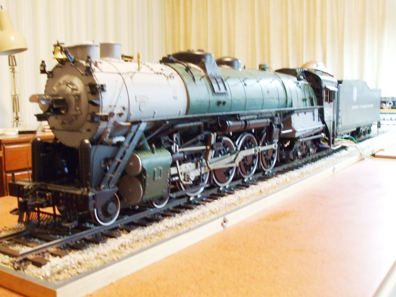
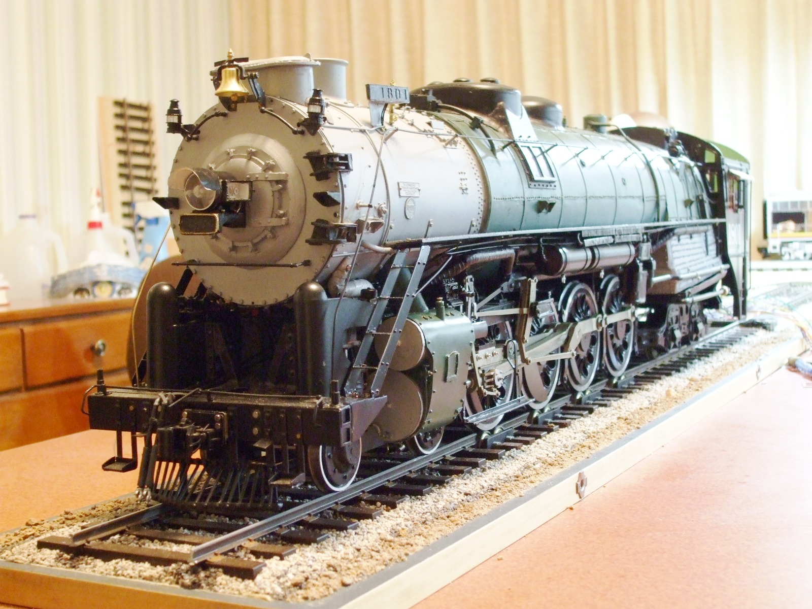
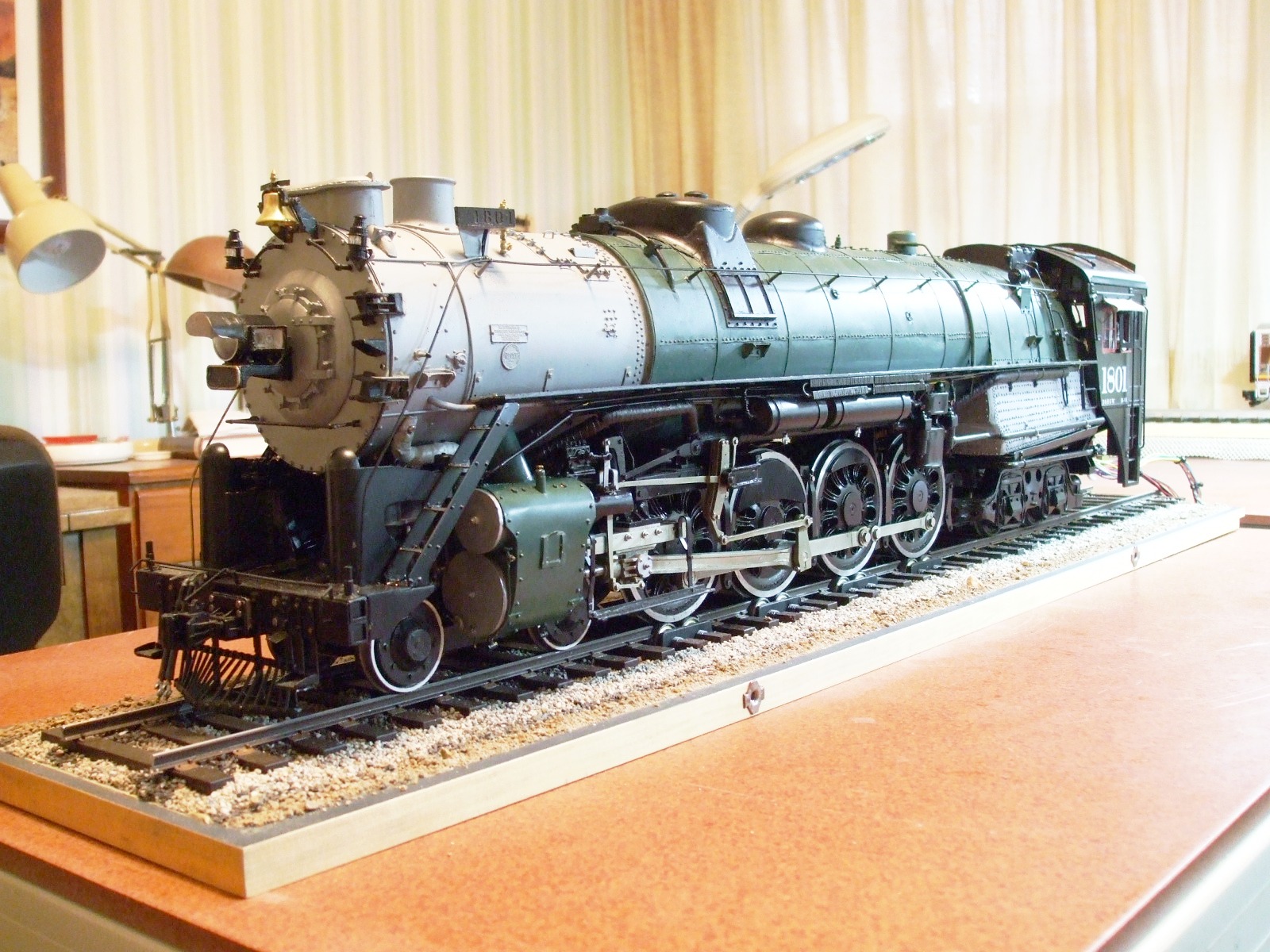
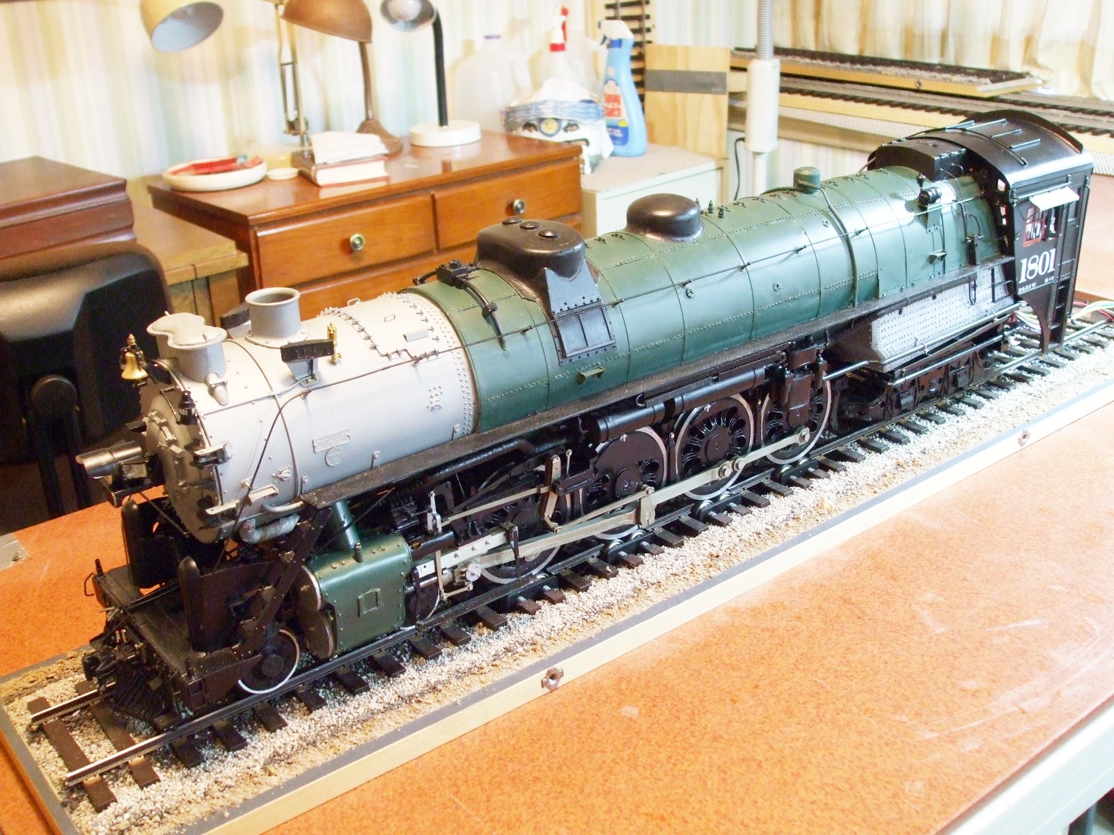
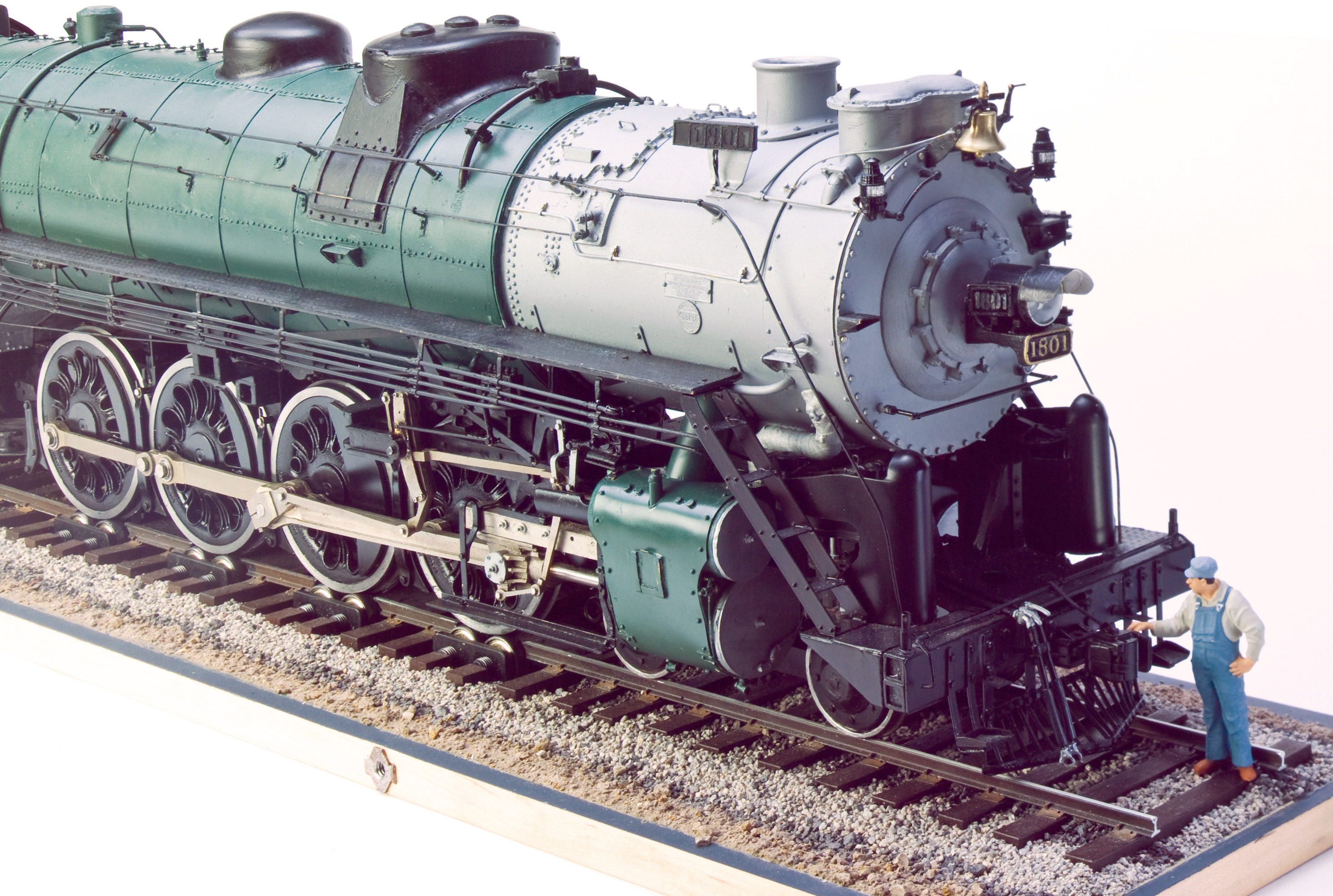
The (Nearly) Completed Locomotive
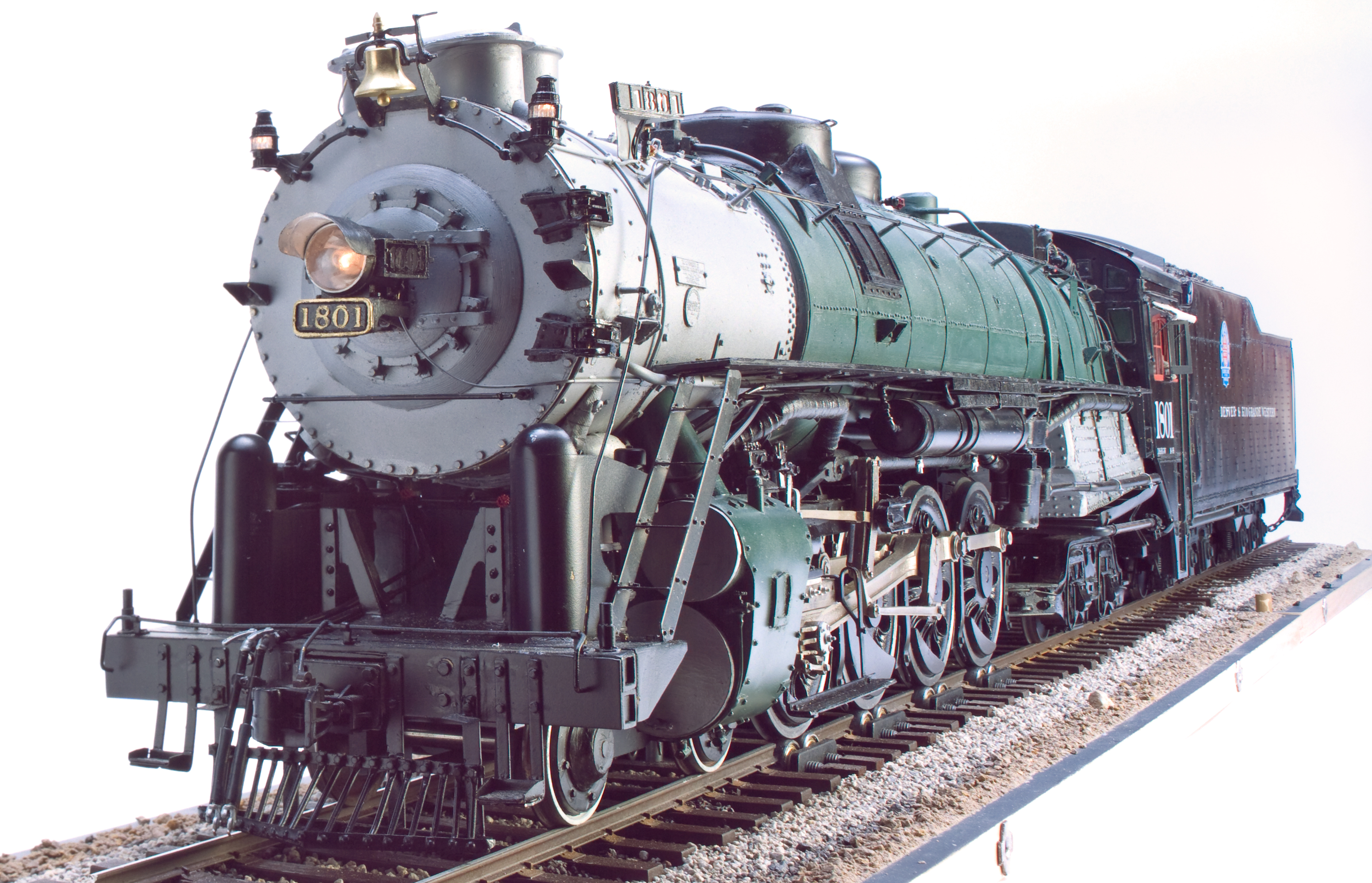
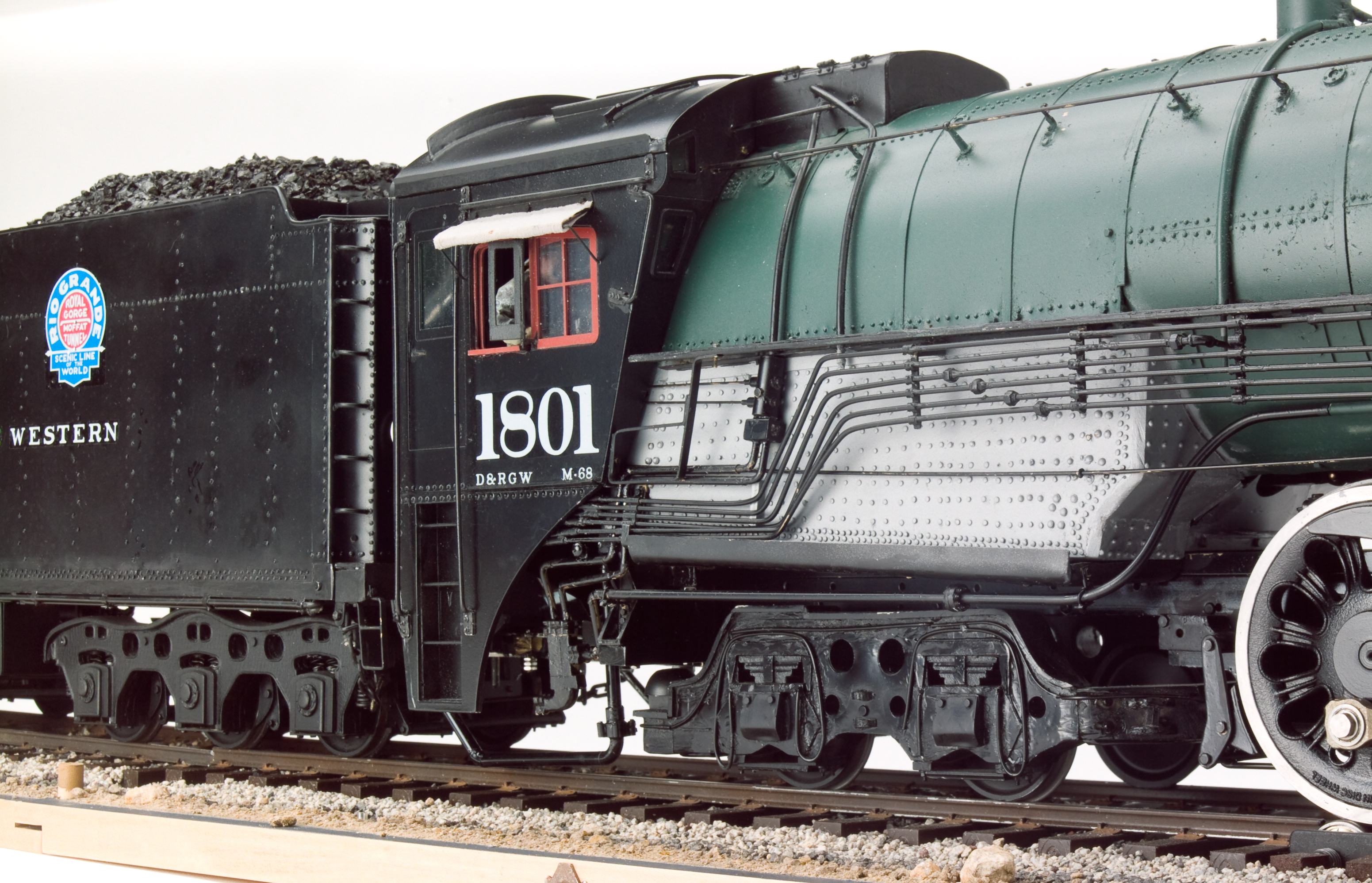
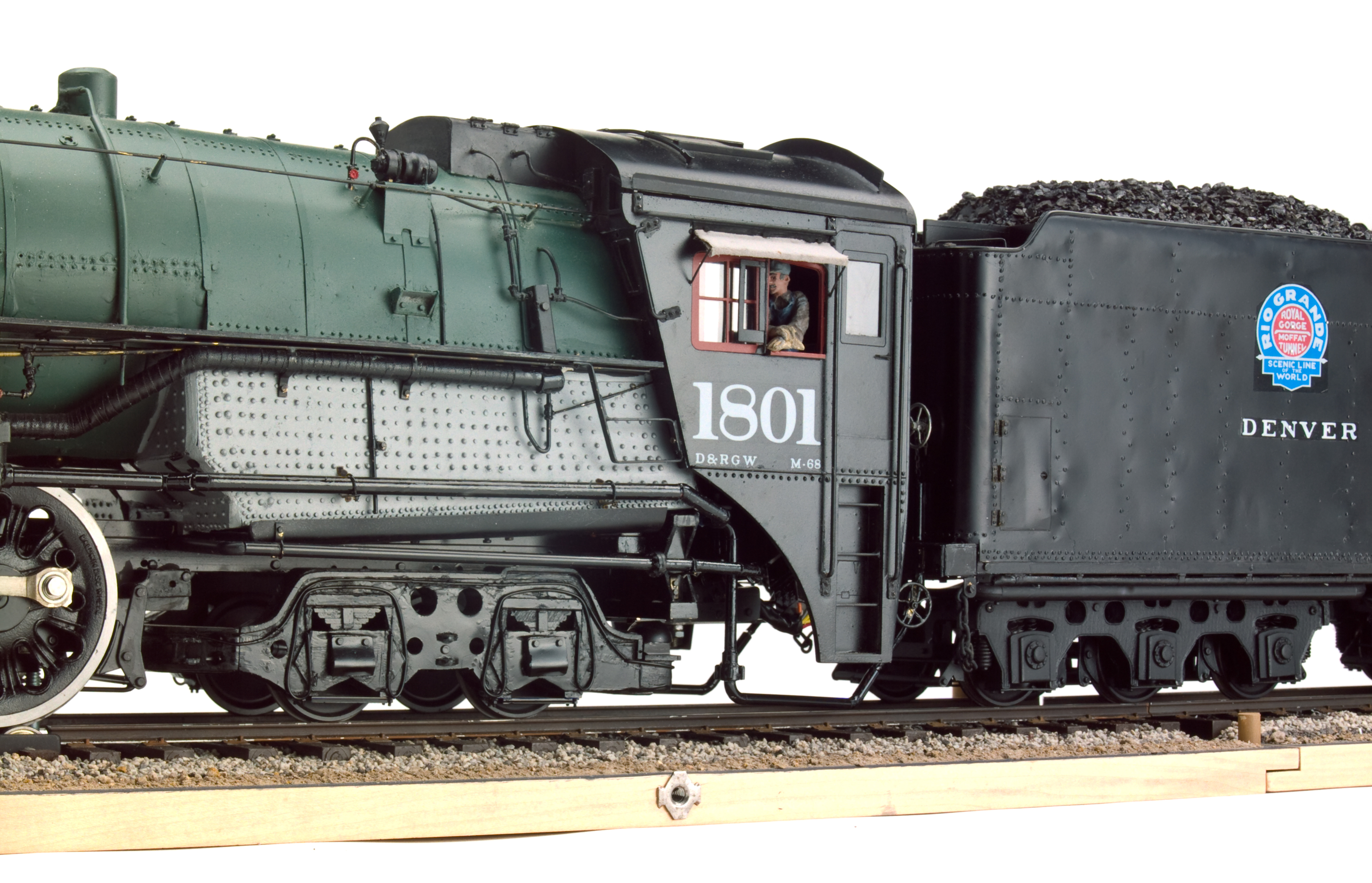
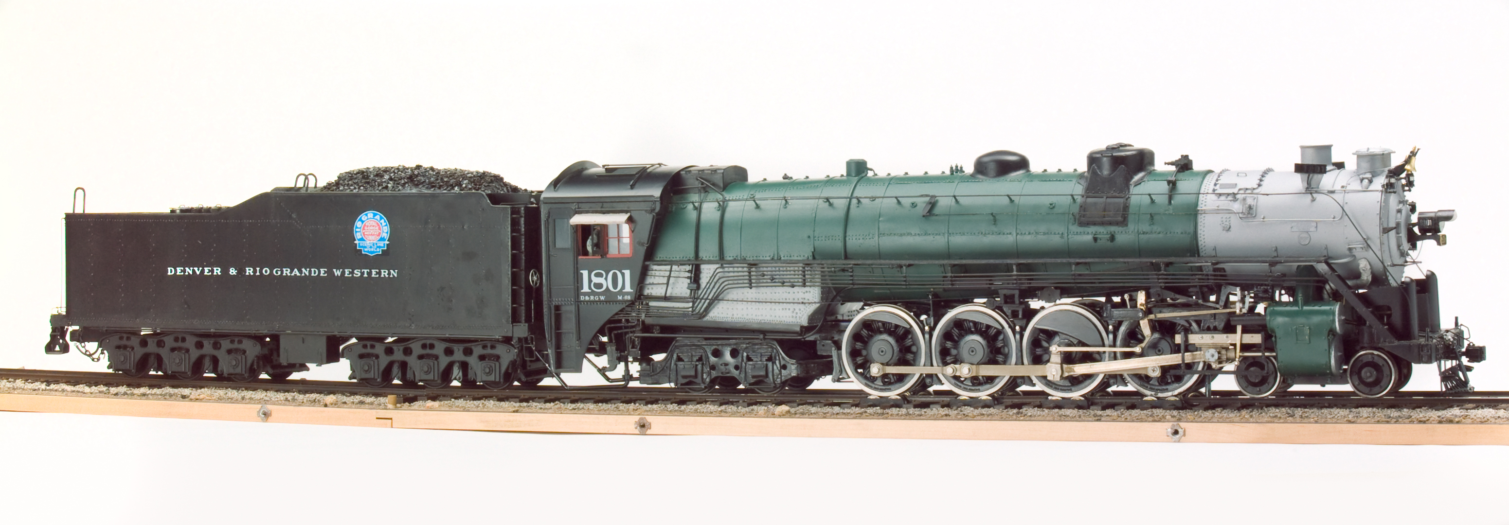
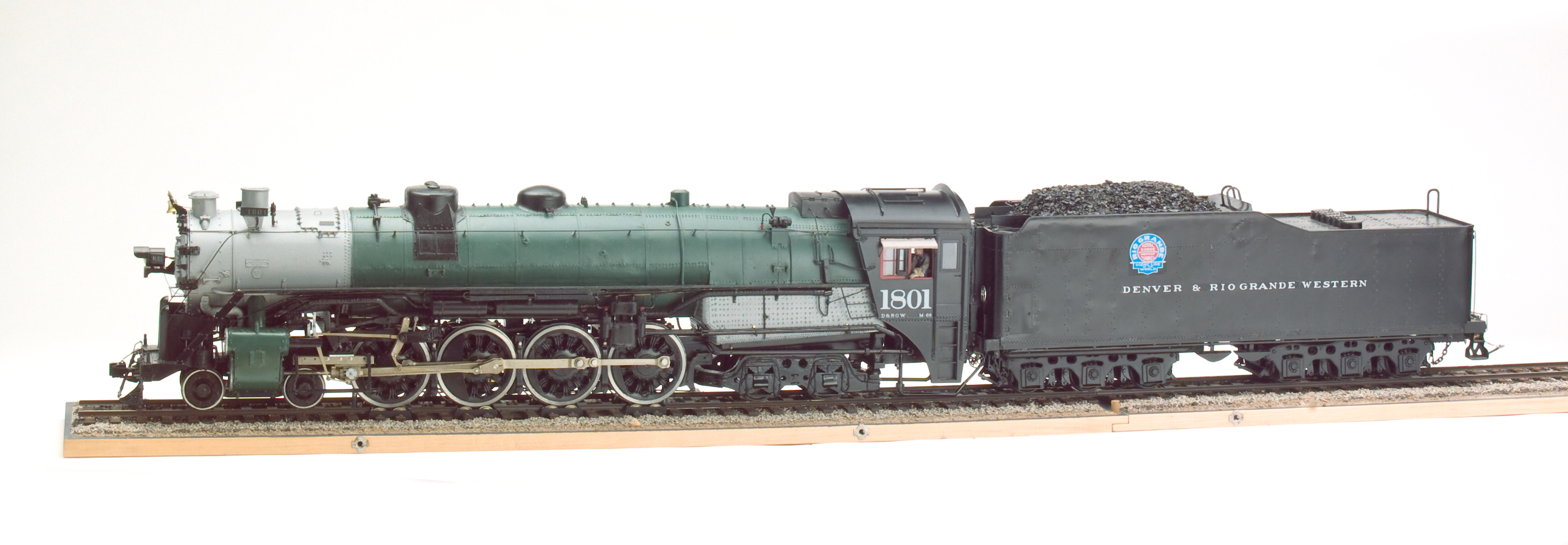
The First Completed D&RGW M-68: #1801
These excellent photos are the work of Mr. Bob Werre. My thanks go to Doug and to Mr. Werre for allowing me to share Doug's fabulous work with fellow model builders and F scale enthusiasts. |
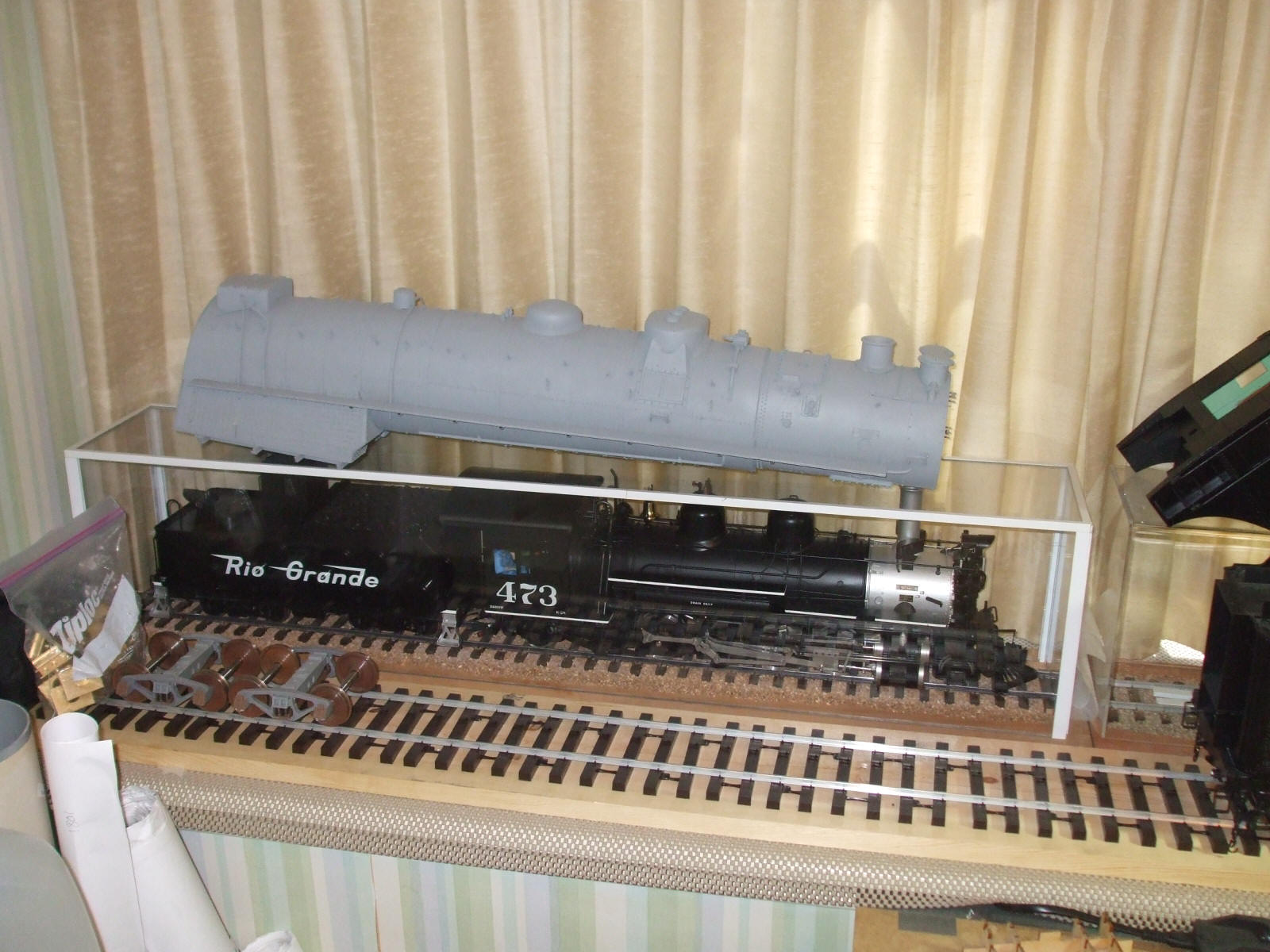
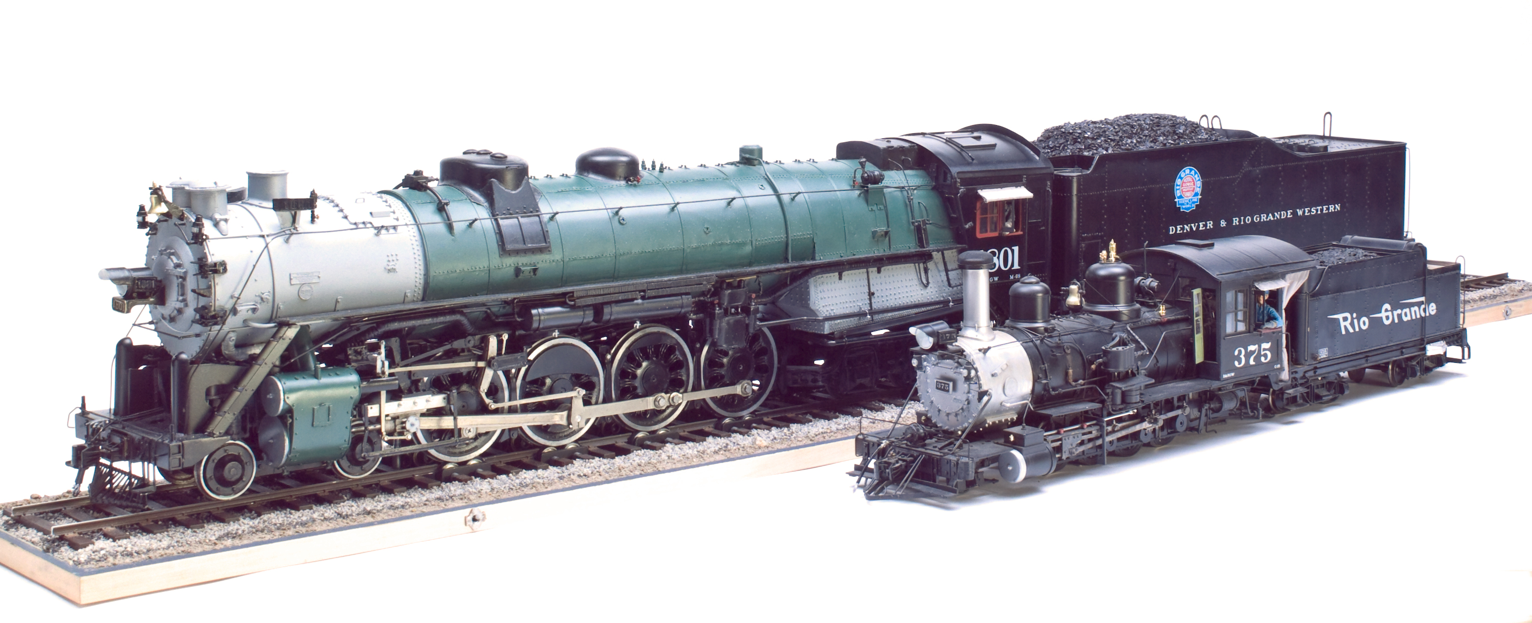
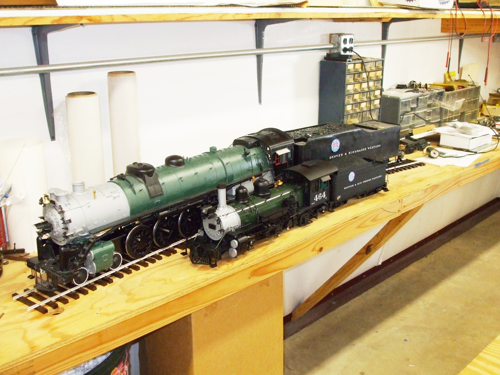
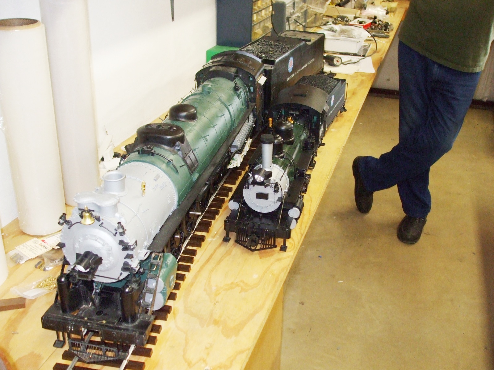
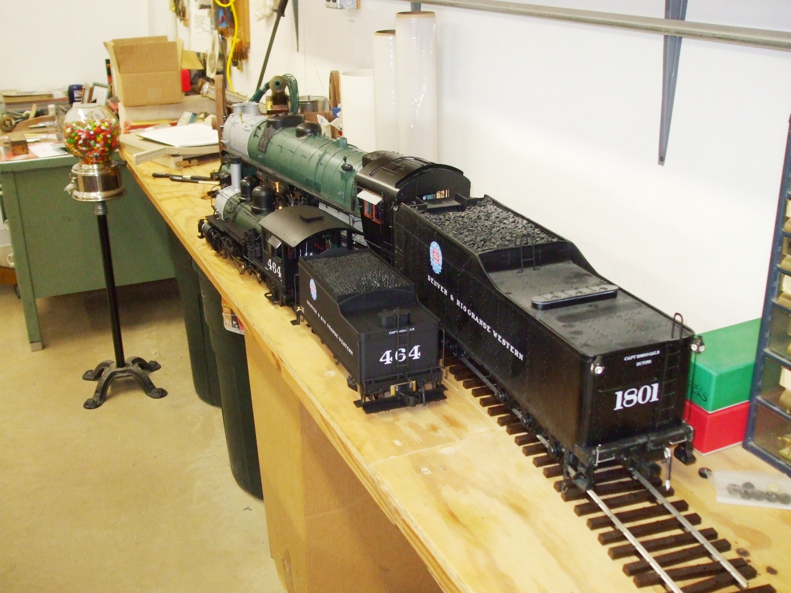
Standard vs. Narrow Gauge
|
%20(9-19-11).jpg) %20(9-29-11).jpg) Additional M-68s:
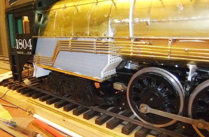
No. 1804, 1802 and 1803 Additional M-68s:
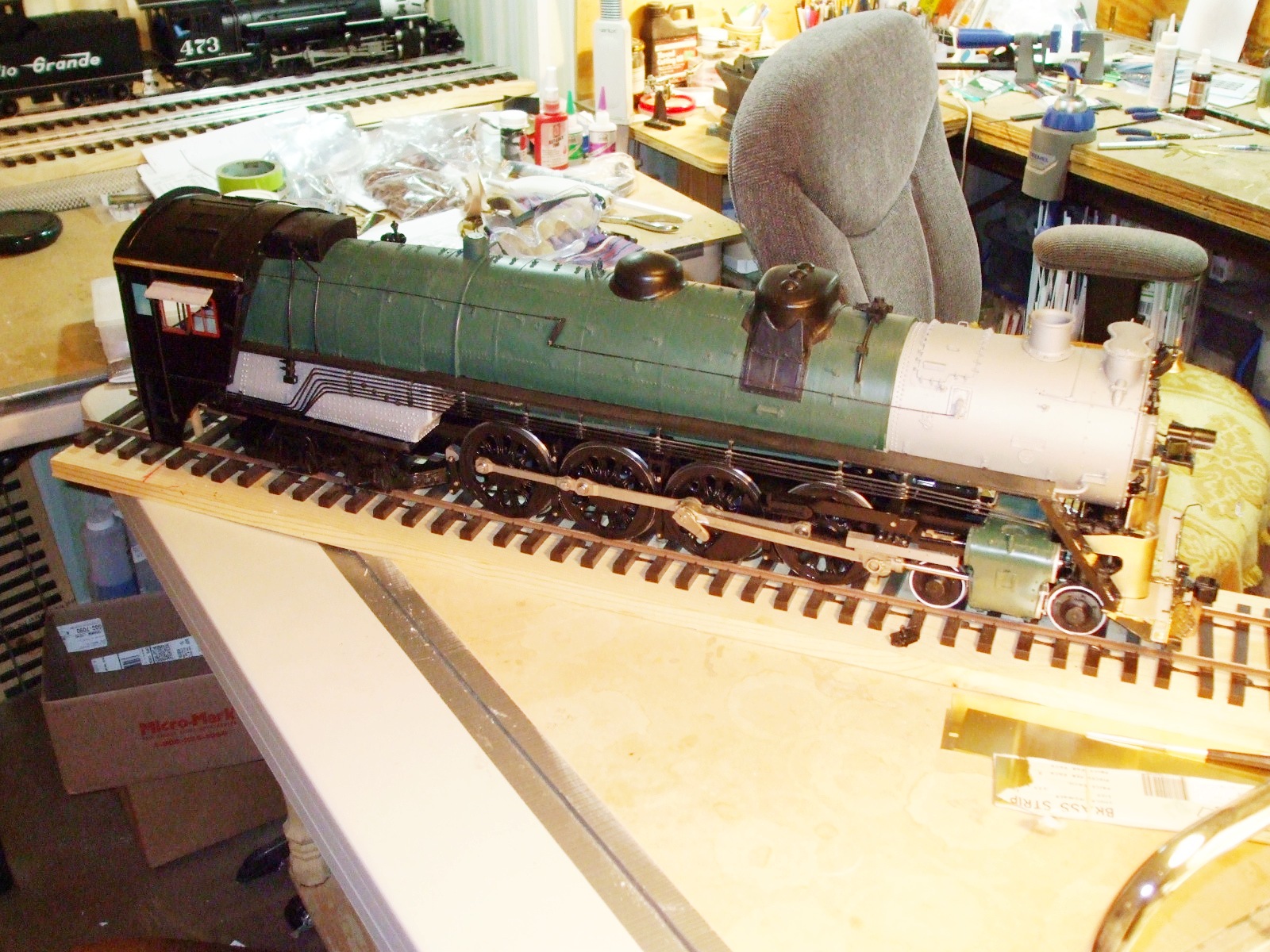
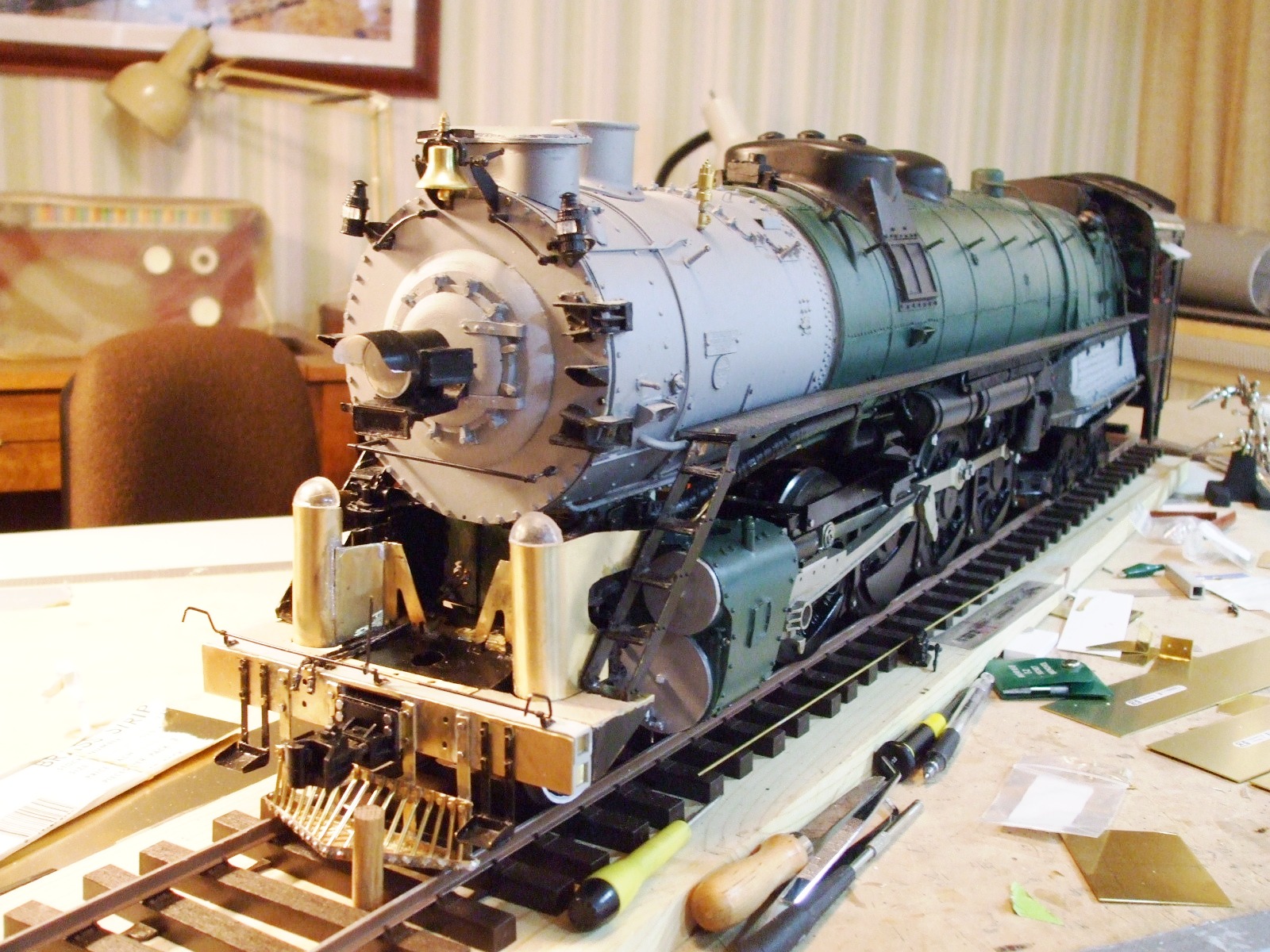
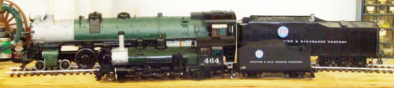
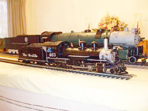
No. 1804, 1802 and 1803(2009-2012) Doug has been actively at work on the other three M-68 4-8-4s since the beginning of the poject, but became more active with engine numbers 1804, 1802 and 1803 following the completion of 1801 in the fall of 2009. The first to be finished is #1804, painted in the black livery with white pin stripe down the running board. According to eyewitness reports, the M-68s wore the D&RGW's green boilered livery at different times throughout their careers, ending, of course, in basic black. These locomotives share the same drive train as the first M-68, but their have been improvement in terms of greater backhead detail, piping, and ease of assembly. These three locomotives are available for sale. Please contact Doug at whemmeter@sbcglobal.net or wdh_marine@sbcglobal.net |
|
.jpg) #1804 #1804
|
|
%20(9-27-11).jpg) #1803
(updated 12-8-11) #1803
(updated 12-8-11).jpg)
.jpg)
.jpg)
.jpg)
.jpg)
.jpg)
.jpg)
.jpg)
.jpg)
.jpg)
.jpg)
.jpg)
.jpg)
.jpg)
.jpg)
.jpg)
.jpg)
.jpg)
.jpg)
.jpg)
.jpg) |
|
%20(10-6-11).jpg) #1802 #1802
|
|
| Next Stop: Doug's First Articulated: The D&RGW L-105 4-6-6-4 | |
|
Last update: 8 December 2011
|
| Copyright 2004-2009 CumberlandModelEngineering.com. All Rights Reserved |
 D&RGW M-68 4-8-4
.jpg)
.JPG)
.jpg)


.JPG)
.JPG)
.JPG)

.jpg)
.JPG)
.JPG)
.JPG)
.JPG)
.JPG)
.JPG)
.jpg)


.jpg)
.jpg)
.jpg)

.jpg)

.jpg)
.jpg)
.jpg)
.jpg)
.jpg)
.jpg)
.jpg)
.jpg)

%208.jpg)


%204.jpg)
%205.jpg)
.jpg)
.jpg)
.jpg)
.jpg)
.jpg)
.jpg)
.jpg)
.jpg)
.jpg)

.jpg)
.jpg)
.jpg)
.jpg)
.jpg)
.jpg)
.jpg)
.jpg)
.jpg)
.jpg)
.jpg)
.jpg)
.jpg)
.jpg)
.jpg)
.jpg)
.jpg)
.jpg)
.jpg)
.jpg)