.JPG)
"Your source for standard gauge modeling in 1:20.3"
|
|
|
"Your source for standard gauge modeling in 1:20.3" |
|
|
George Konrad Gallery
|
|
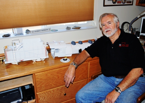
George Konrad, who hails from
Beaumont, California, is best known as an
prolific author in the model
railroad press, having authored over 60 articles on such diverse topics
as 19th century mining and industrial operations to large scale
kitbashed locomotives and rolling stock. In
real life he is retired from IBM field service and spent 20 years in the
US Air Force Auxiliary as an aerospace education officer, retiring as a
lieutenant colonel; but he now facilitates product development for
Accucraft
Trains and has worked many years as a custom outdoor layout
builder. But his singular claim to fame in F scale is the construction
of the first 1:20.3 standard gauge mallet (see below). He may be reached at
gkstudios@msn.com |
|
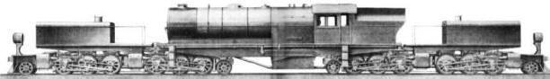
The first standard gauge mallet type steam locomotive to be built in 1:20.3 is the work of George Konrad who was inspired by Barry Bogs' model of the same locomotive in 1:22.5 scale, Gauge 3. The prototype locomotive at right, built in 1916 by Alco's Schenectady works for the Denver & Salt Lake RR, a line absorbed into the Denver & Rio Grande Western in 1947, was a 2-6-6-0 compound with 55" drivers and exerted about 77,000 pounds tractive effort (hence the D&RGW's designation L-77). The L-77s were short lived on the D&RGW, all of the class being dismantled by mid 1952. As an interesting side note, some of the L-77 class began life in 1908 as 0-6-6-0 mallet compounds for use in both hump yard and helper service and were later equipped with a pony truck for better tracking. On the D&SL, or "Moffat Road," they were heavy freight power; but on the Rio Grande, they were midget mallets in comparison with the road's massive simple articulated L-131 2-8-8-2 and the two classes of 4-6-6-4 Challenger sported by the Grande. Like all Rio Grande standard gauge steam, save for a lowly C-28 class 2-8-0, none escaped the scrappers' torch. |
.jpg) Research
& Resources: Research
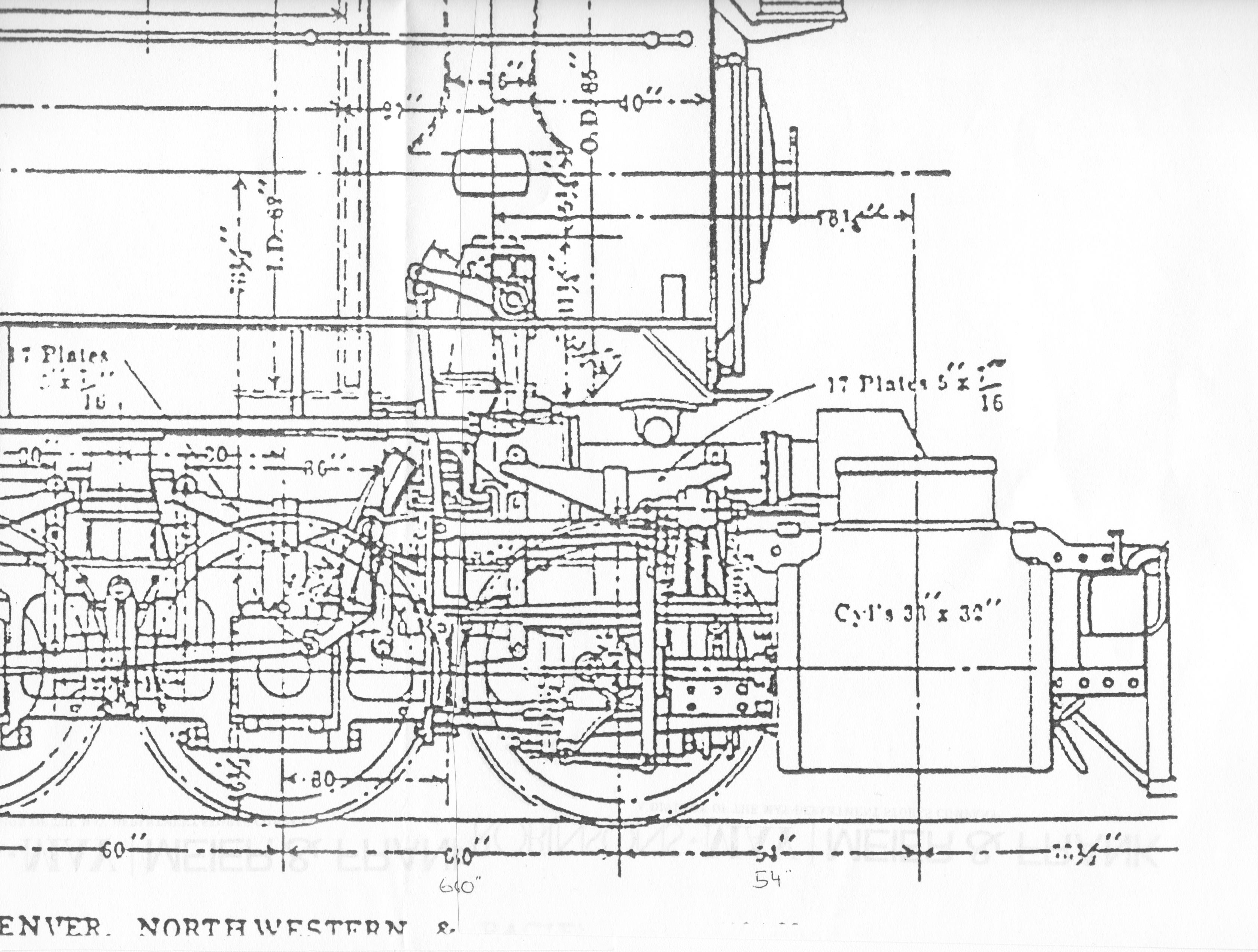
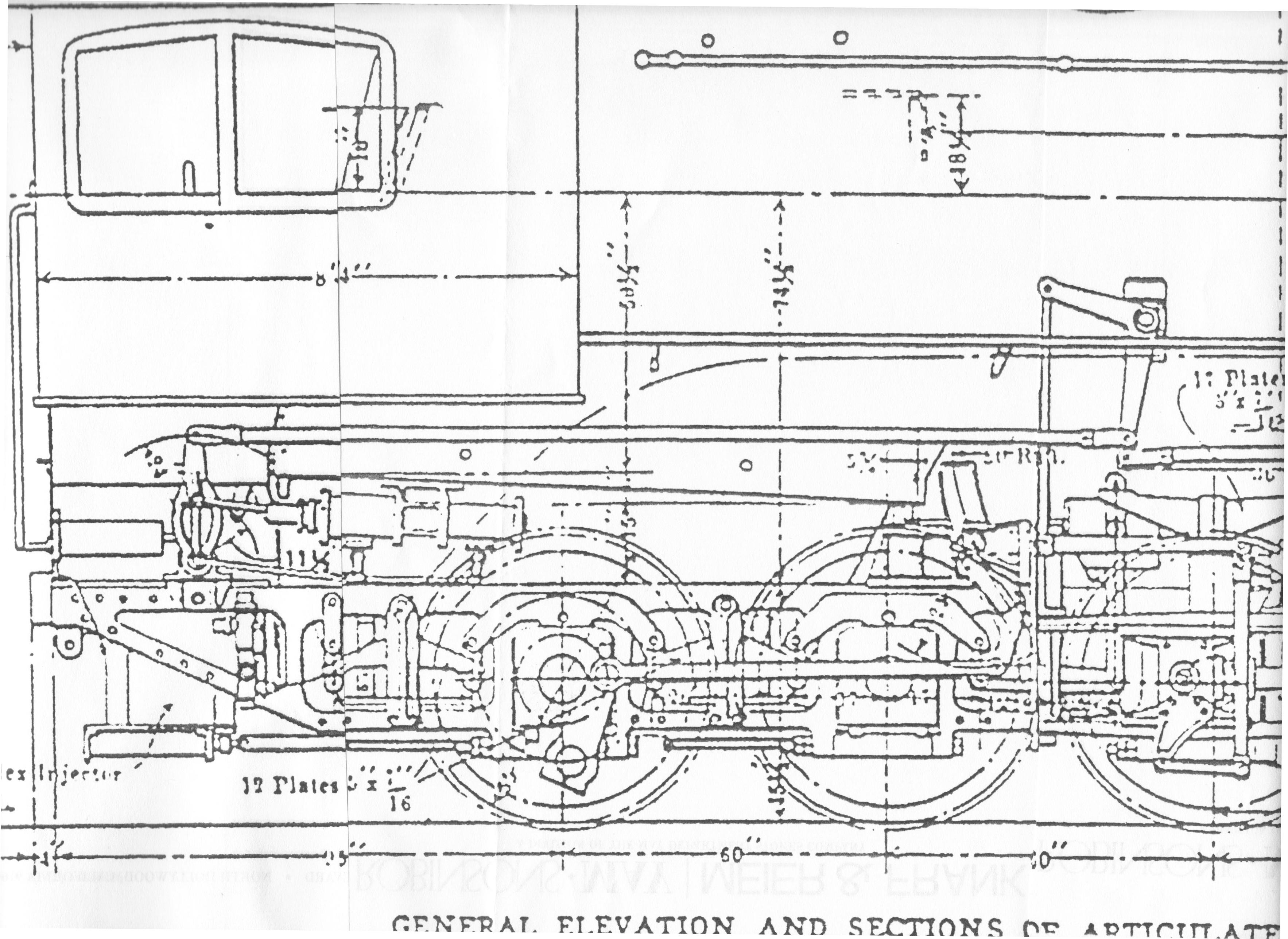
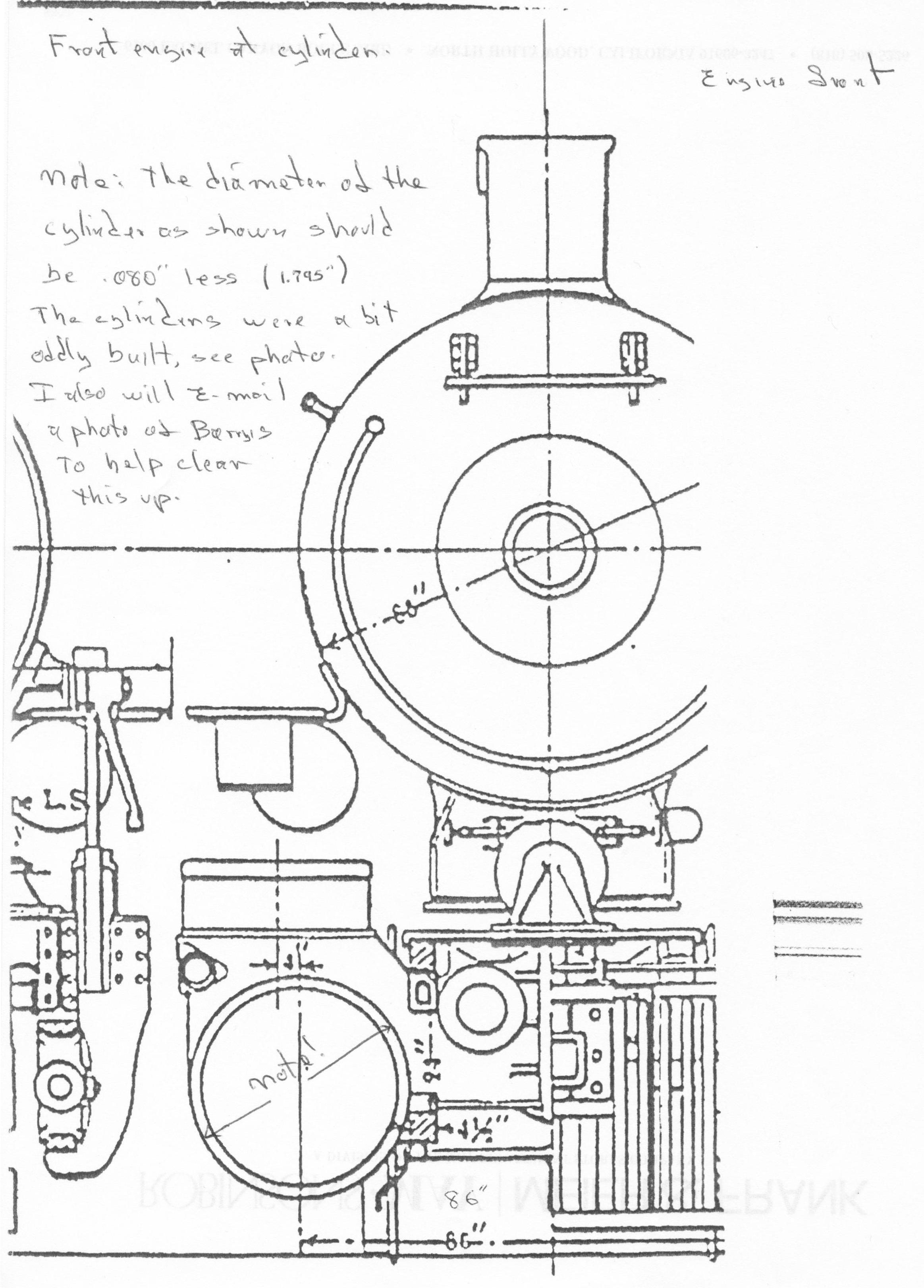
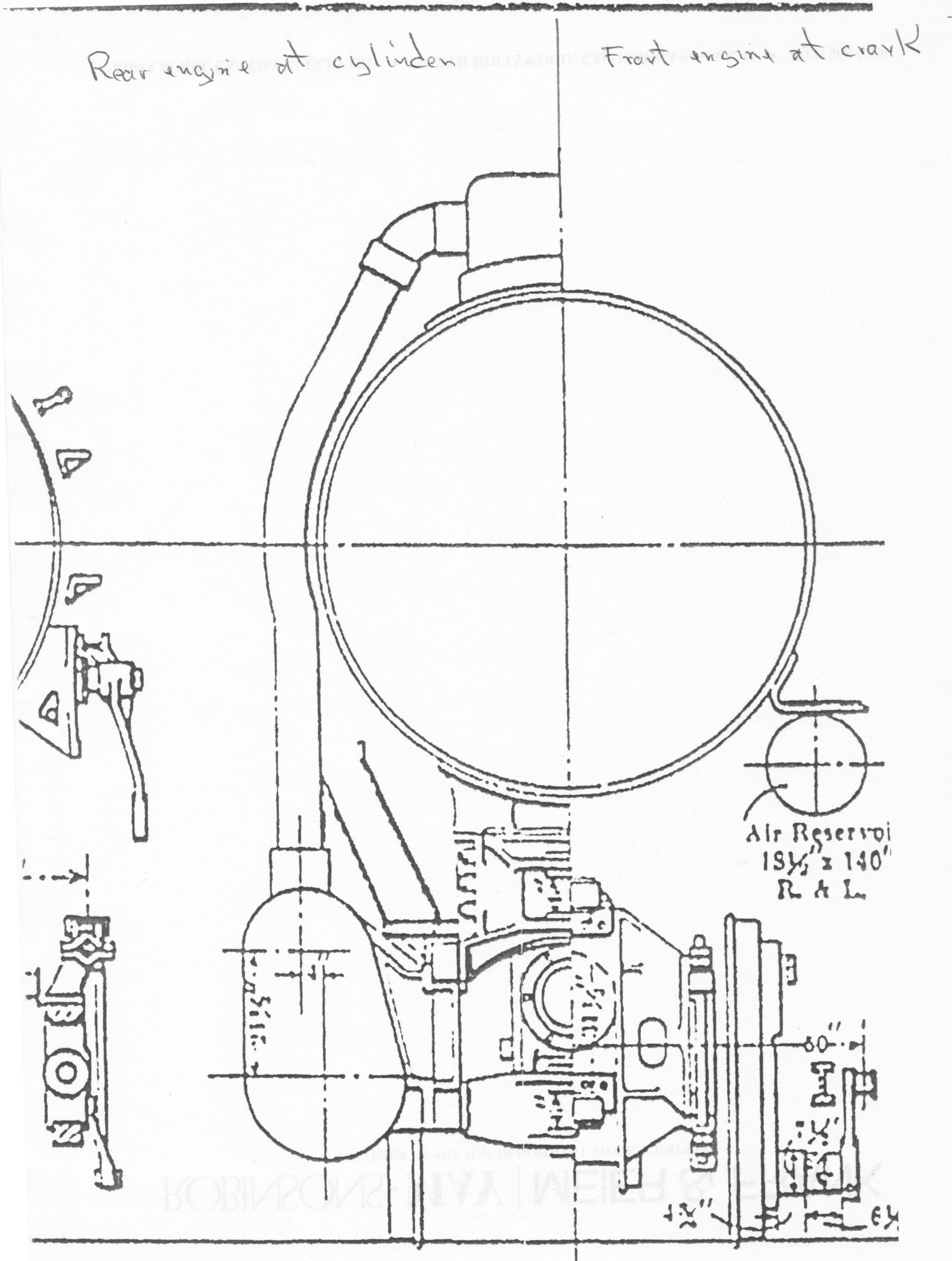
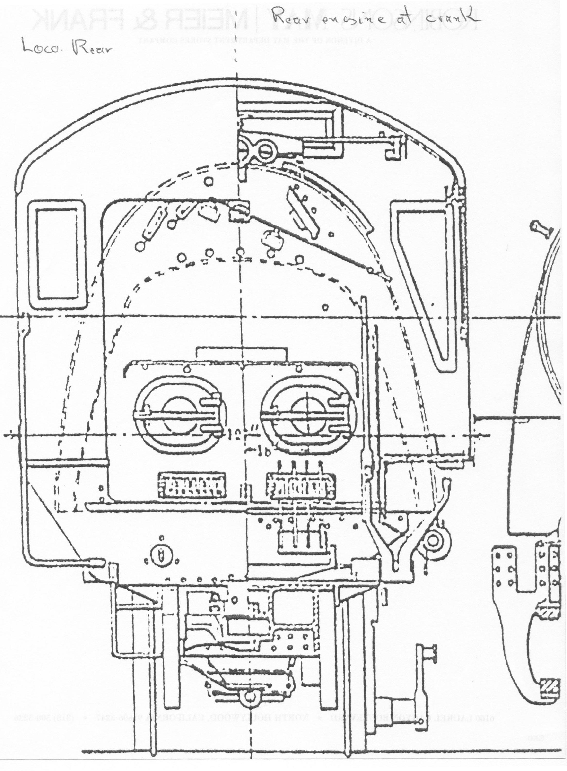
& Resources:George's D&SL 2-6-6-0 is his first effort in 1:20.3 standard gauge and is intended for outdoor operation around 370 feet of dual gauge garden railway with about 7'-6" minimum radius. Since there are no readily available prototype drawings for this particular locomotive, dimensions for the F scale model have been approximated from several different sources: (1) the D&RGW's own folio drawing, which provides rudimentary wheelbase measurements, (2) a set of elevation and section drawings for the predecessor 0-6-6-0 which some of the L-77s were based upon, and (3) the O scale builder's drawings that were made for Pacific Fast Mail's imported brass O scale model (kindly provided by the current owners of the non-defunct PFM product line). Several of these drawings are reproduced below:
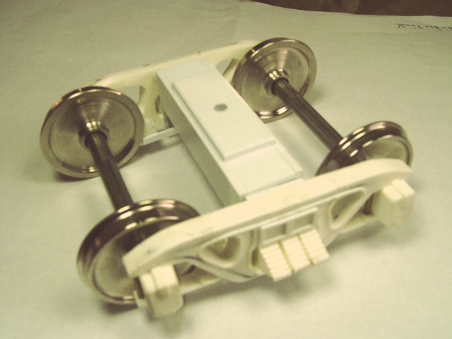
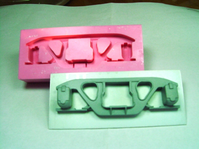
George's model is a combination of scratch building and adaptation. The tender, tender trucks, boiler, cab, and lead truck are all scratchbuilt from either brass, styrene, or urethane castings based upon styrene masters. The chassis however is the result of regauging two brass and steel Accucraft 1:29 scale, Pennsy K4s Pacific mechanisms with new axles, frame spreaders, frame extensions, and cylinder halves. It is on this part of the project that I have had a prominent role, George having asked me (Dave, your host) to make the Accucraft mechanisms work and to look like a small mallet rather than a couple of of truckless 4-6-2s! But more on that below. |
|
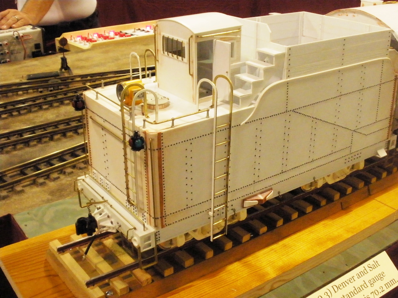
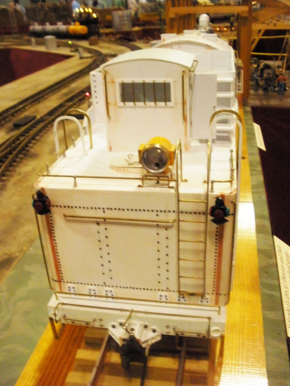
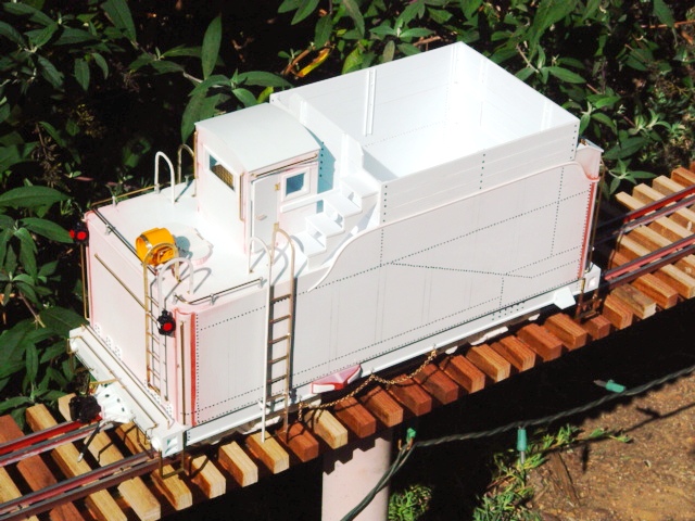
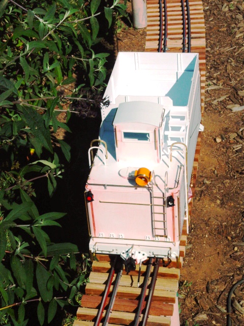
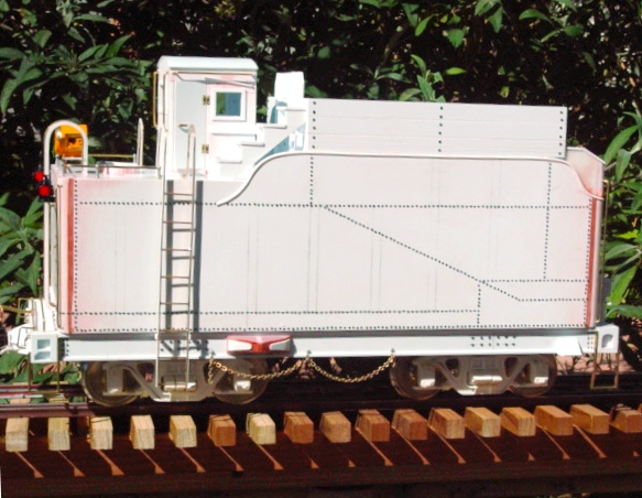
The Tender
|
|
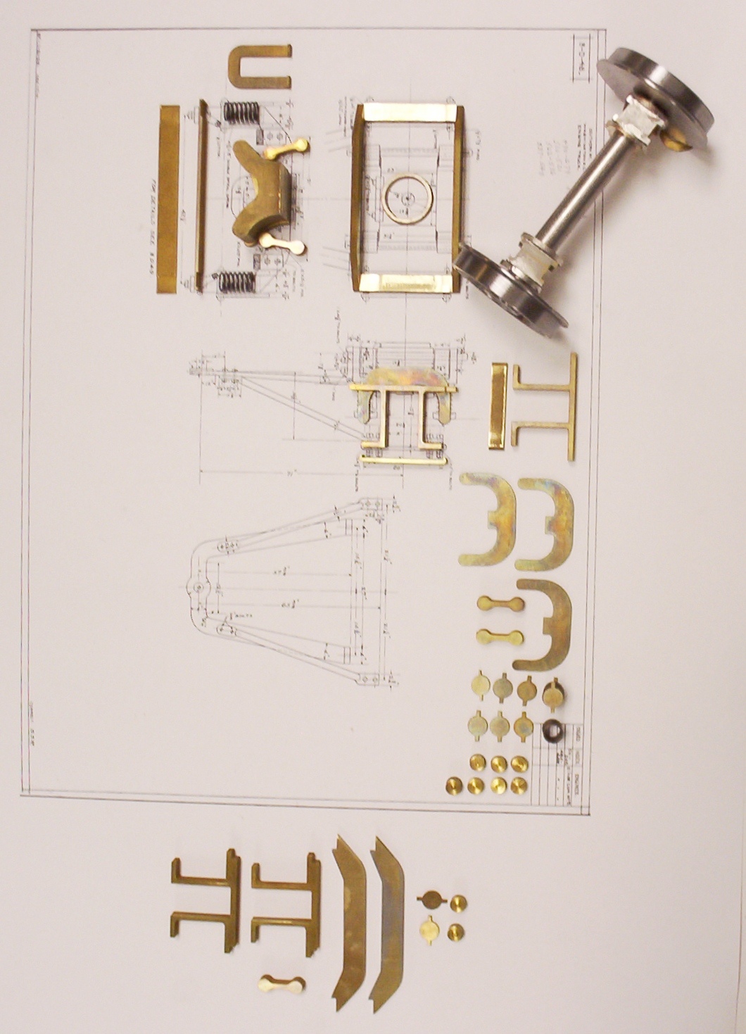
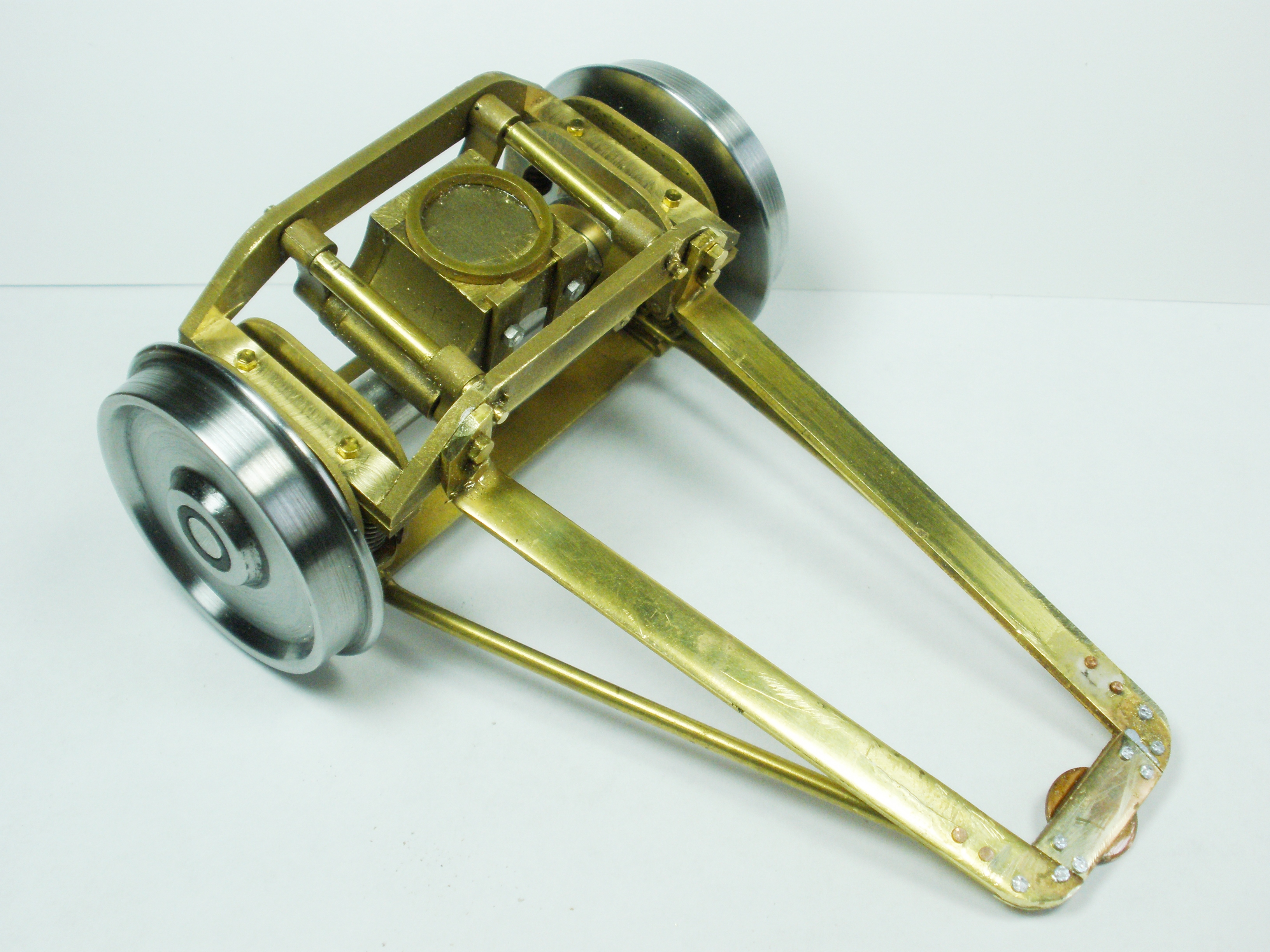
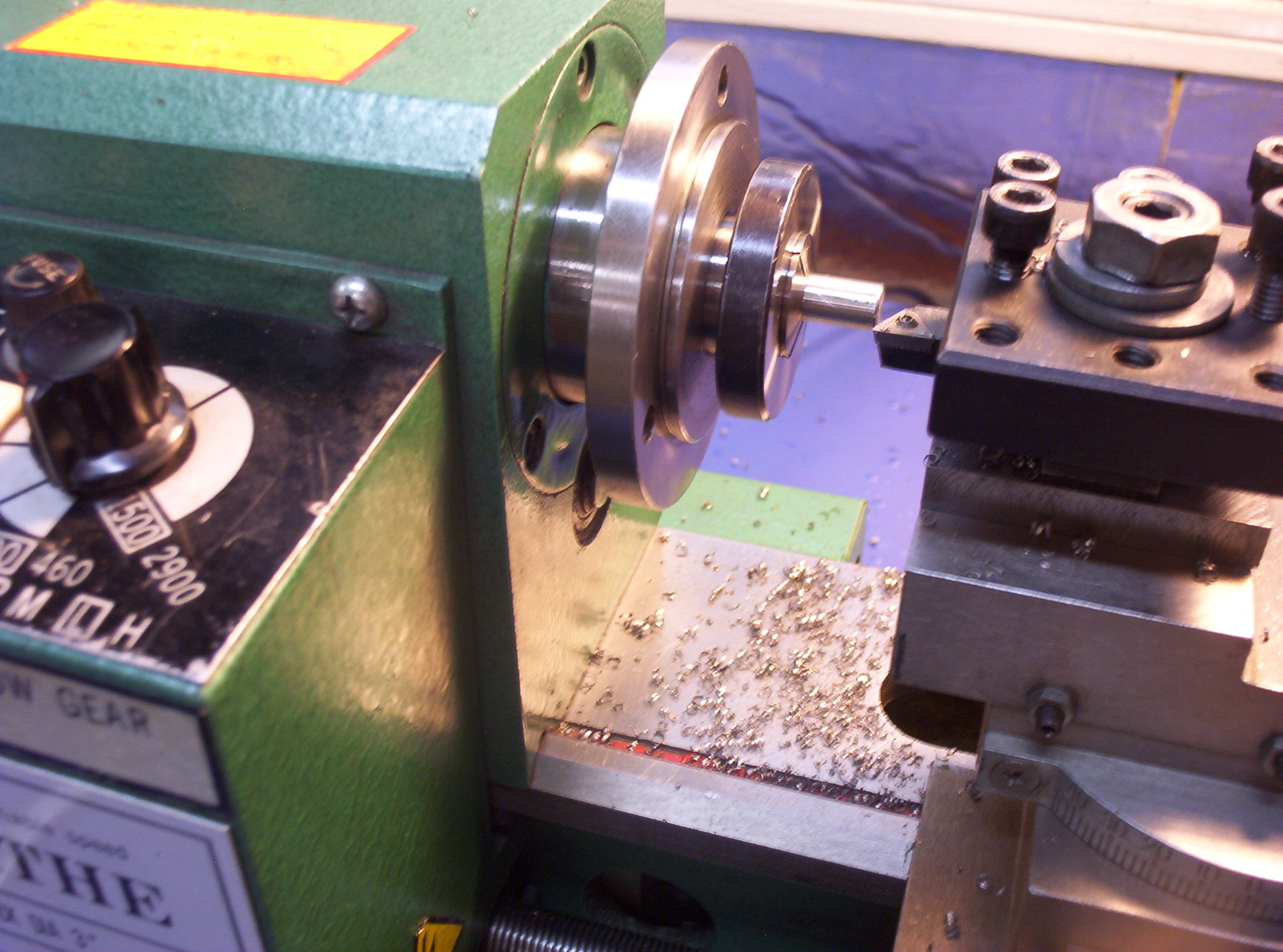
Pony Truck Since no detailed plans were available for the lead truck on the D&SL 2-6-6-0, a compromise solution was to use scale drawings for a built-up lead truck of roughly the same design. One which I happened to have on hand came from a late 19th century Southern Railway G-Class 2-8-0. After the original Southern Railway linen blueprints were scanned, I imported their raster image into AutoCAD, traced them, and then generated separate part drawings for each part of the truck. Since this was not to be a casting pattern, but a one-off model, each part was cut at 100% exact scale size from either brass sheet or brass bar stock on my Japax Wire EDM. I also supplied the 30" wheels and axle, the former adapted from 7/8" scale steel wheels made by Gary Watkins of Sierra Valley Enterprises. These were spot on with respect to their OD and required only a bit of facing on the lathe to make them appropriate for F scale. The remaining assembly work George did in his own workshop, including the addition of the radius arm.
|
|
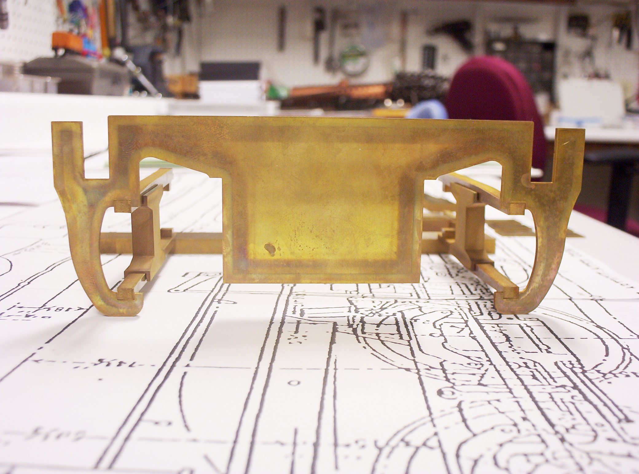
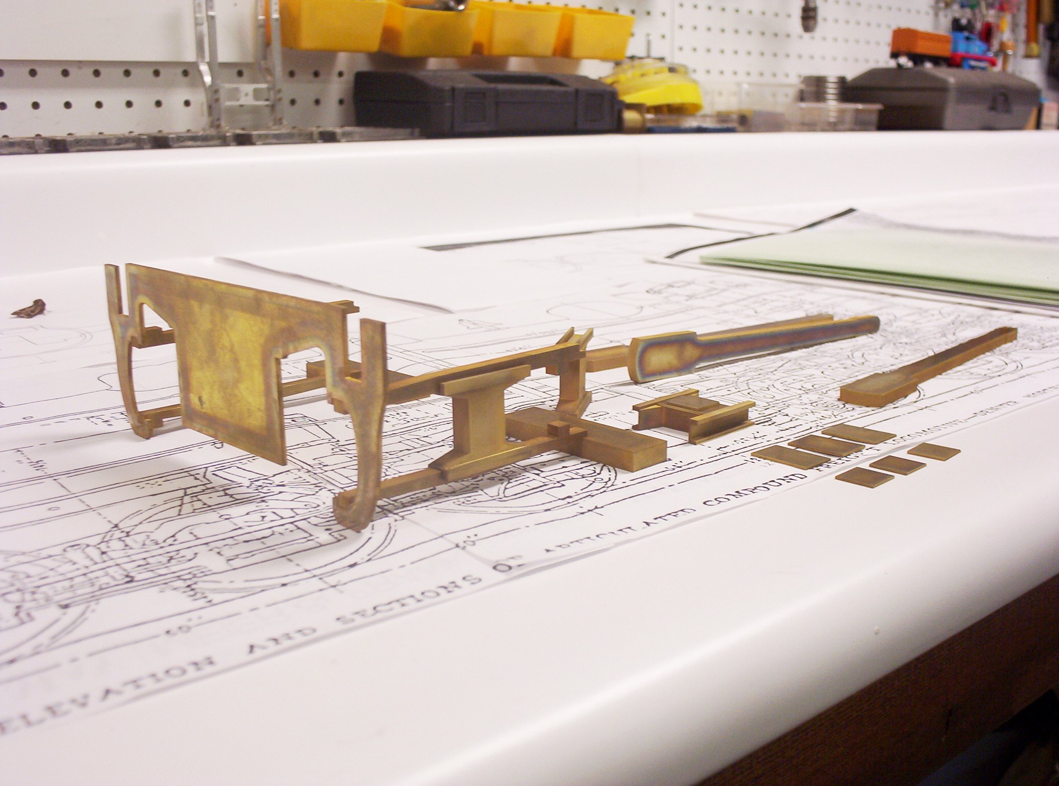
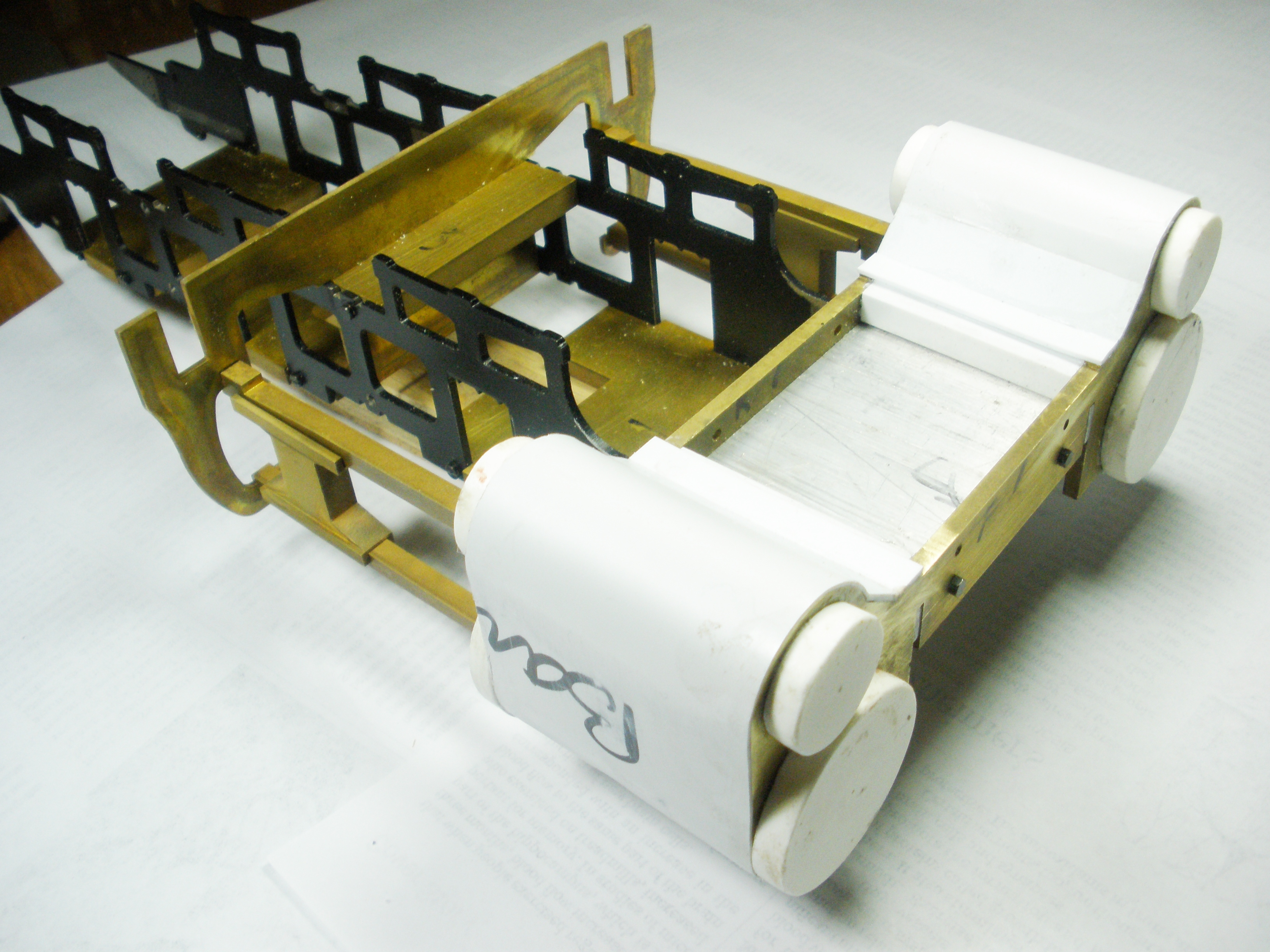
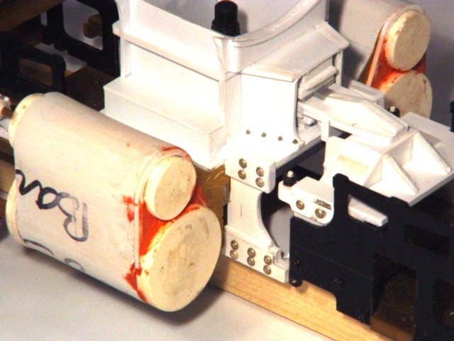
The Chassis The biggest challenge with George's project has been how to come up with a plausible chassis without going to all the trouble of building everything from scratch. The solution that George arrived at was to use two 1:29 scale Accucraft Pennsylvania Railroad K4s mechanisms since their axle spacing between the drivers was very, very close to the L-77's 5'-0" in 1:20.32. This is the point at which I got involved in the project, and my job has been to regauge and modify them into the high and low pressure units of a mini-mallet. I began by drawing both the Accucraft frames and frame spreaders (as is) in AutoCAD and then doing the same for the 2-6-6-0's frame, cylinders and crosshead guide spreaders in both elevation and section views (or at least as best as one could estimate these from the somewhat sketchy 0-6-6-0 drawings posted above). The challenge has been both to estimate the missing pieces from the D&SL engine and to figure out how the narrow (.080" thick) laser cut frame halves of the Accucraft model could be modified to look like the 4.5" thick bar frames of the prototype--which are both longer in some places, shorter in others, and generally ride higher than the Accucraft frames.
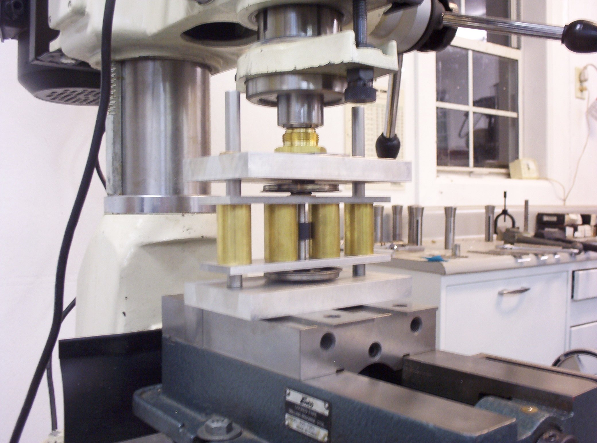
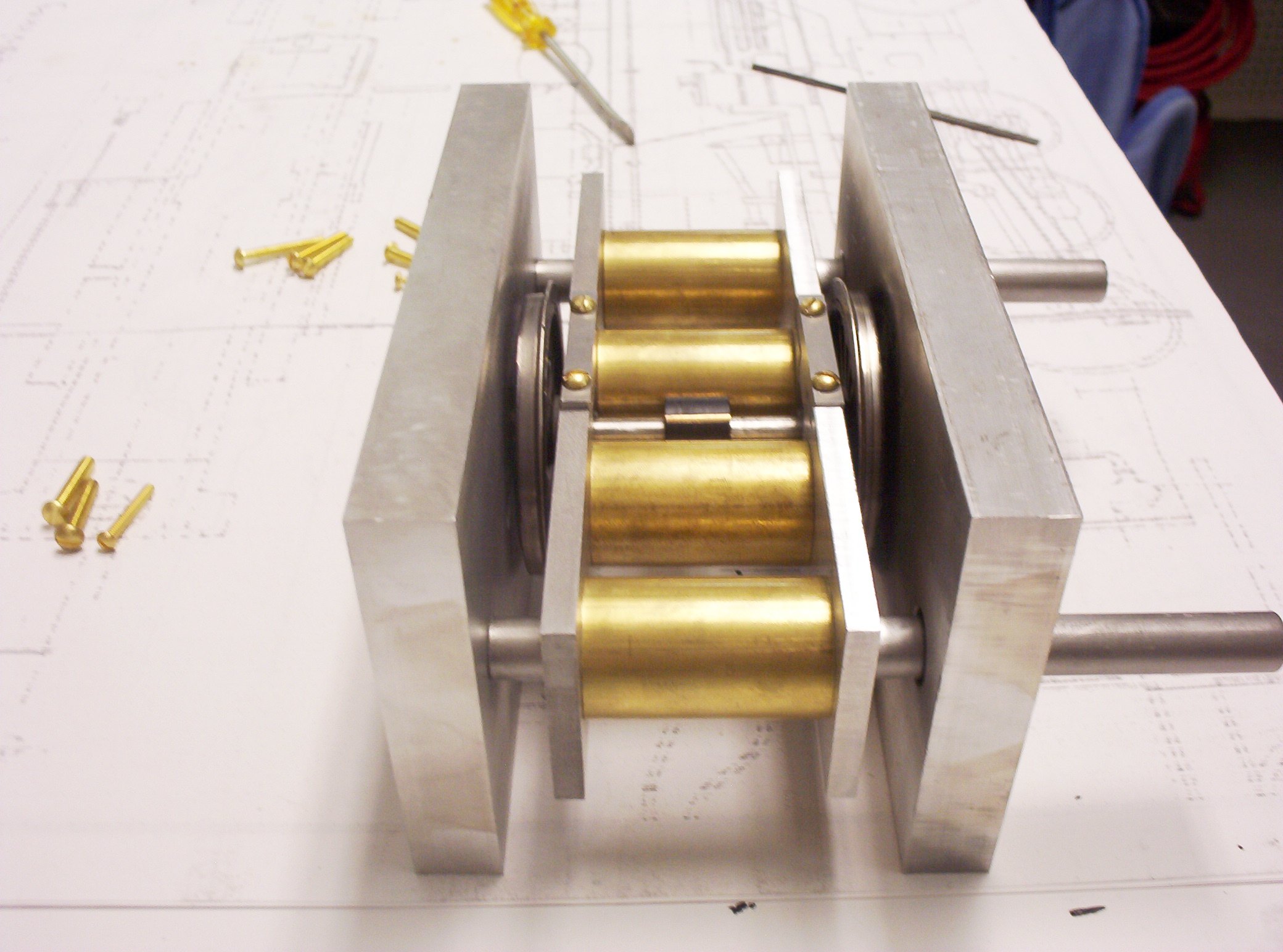
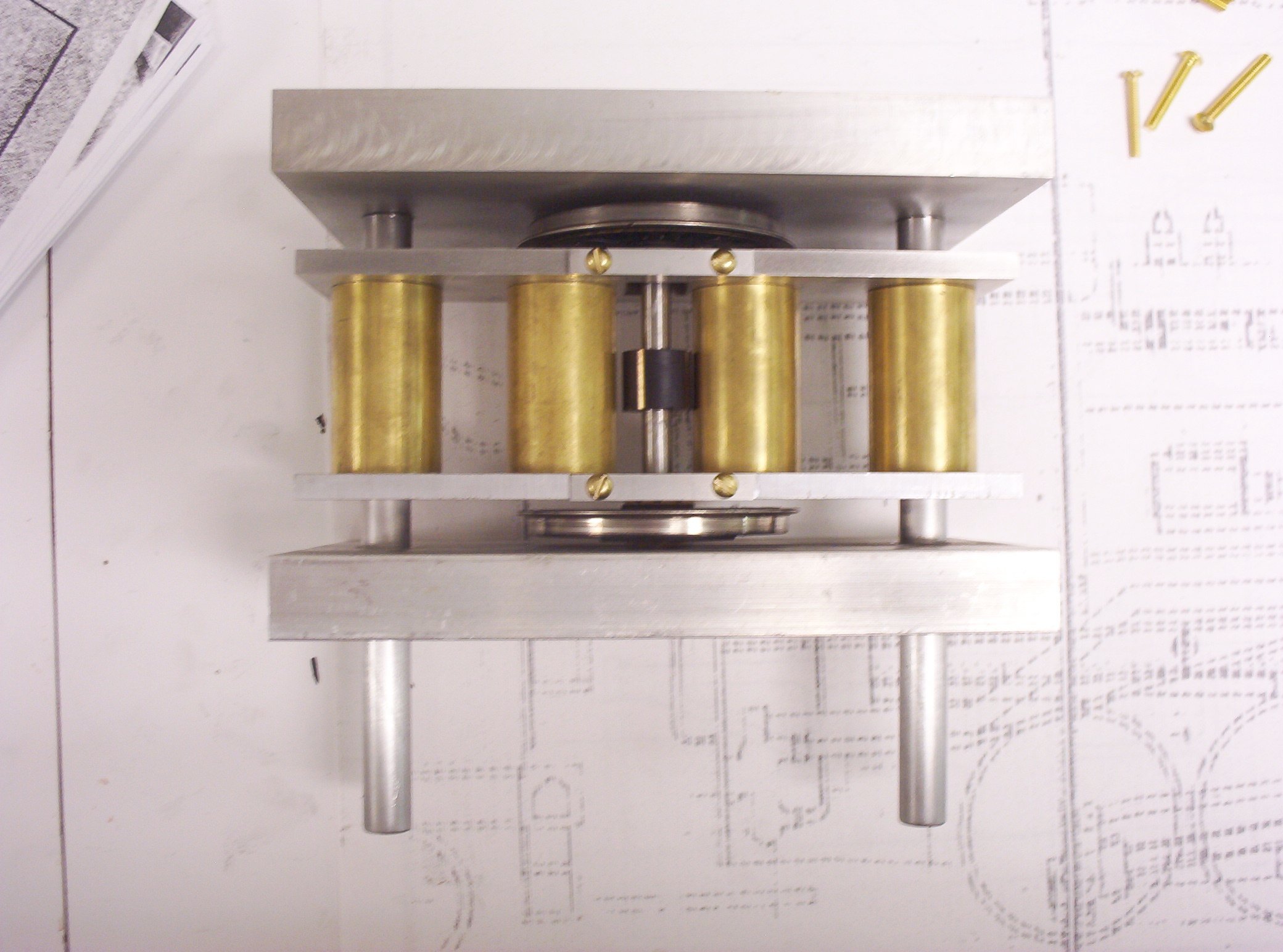
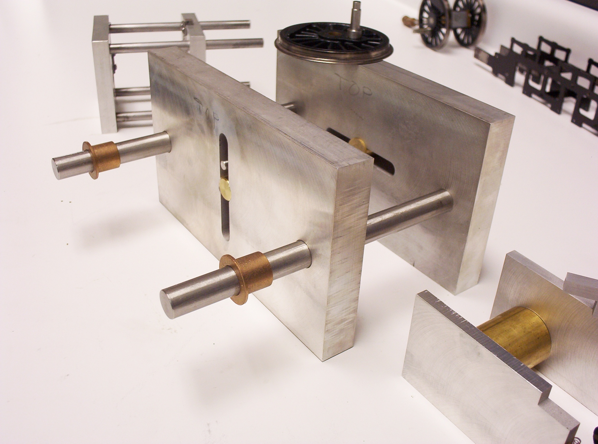
Two of the original Accucraft axles had been knurled on their ends using a straight knurling tool. So I decided to duplicate these axles first in F Gauge, using another Little Machine Shop aftermarket product (a "scissors" style knurling tool holder mounted in the lathe's tool post), but found the knurls actually to be unnecessary, and really something of a problem, when it came time to press the drivers onto their axles. The straight knurls, which raised the OD on the ends of the axles by almost .005", were a bear to press into each driver, causing so much interference that the 1/4" aluminum inner plates of my quartering jig were bent (hence the two additional brass spacers shown in the jig below). In the end, press fitting the 8mm axles into the Accucraft drivers and some red Loctite proved sufficient to hold everything together (so tight a fit that in a test with a spare pair of drivers, I could not twist that set of drivers about their axles with the substantial strength of my bare hands). The Quartering Jig
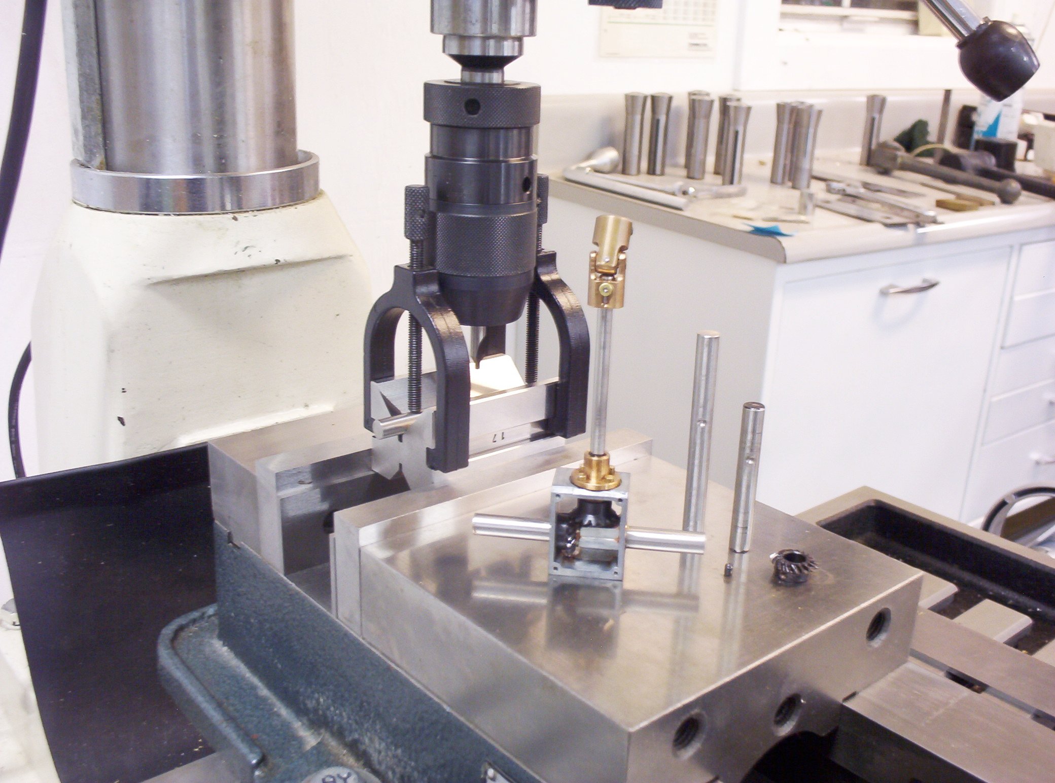
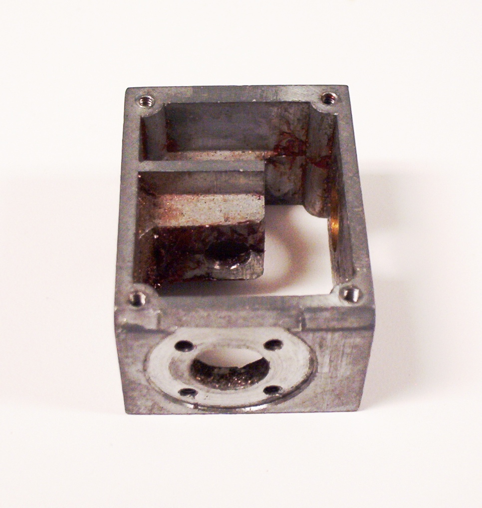
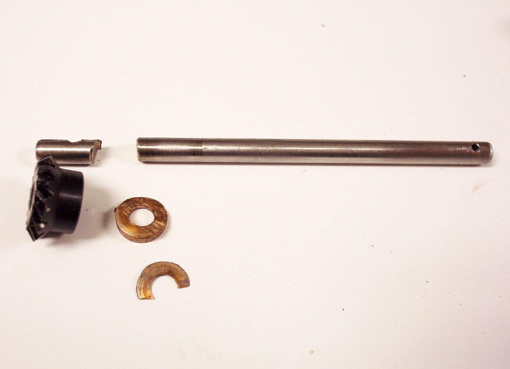
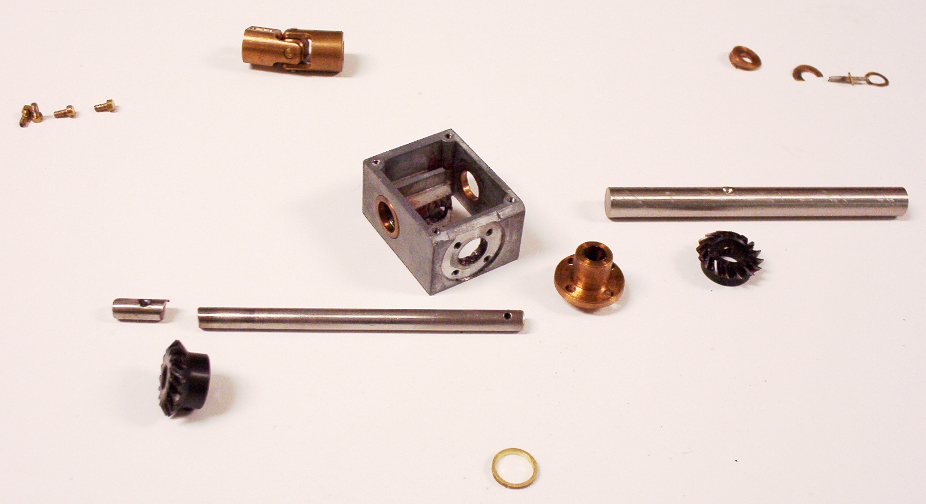
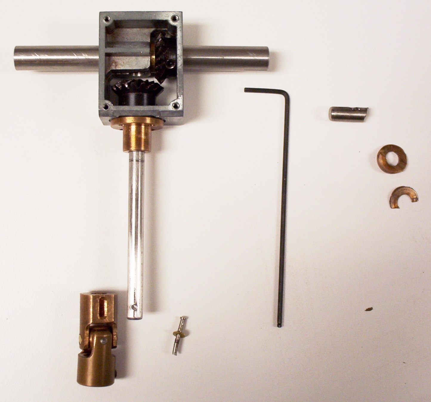
Modifying The Accucraft Gearbox
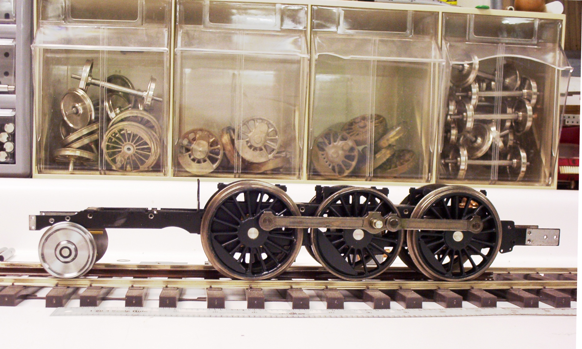
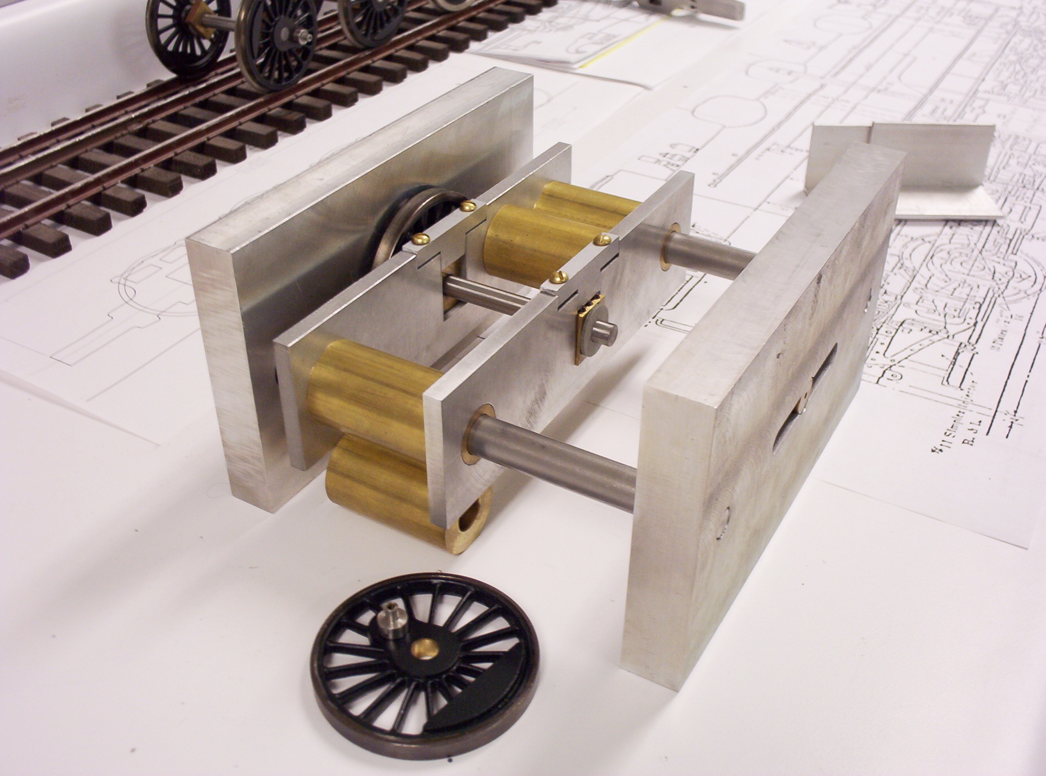
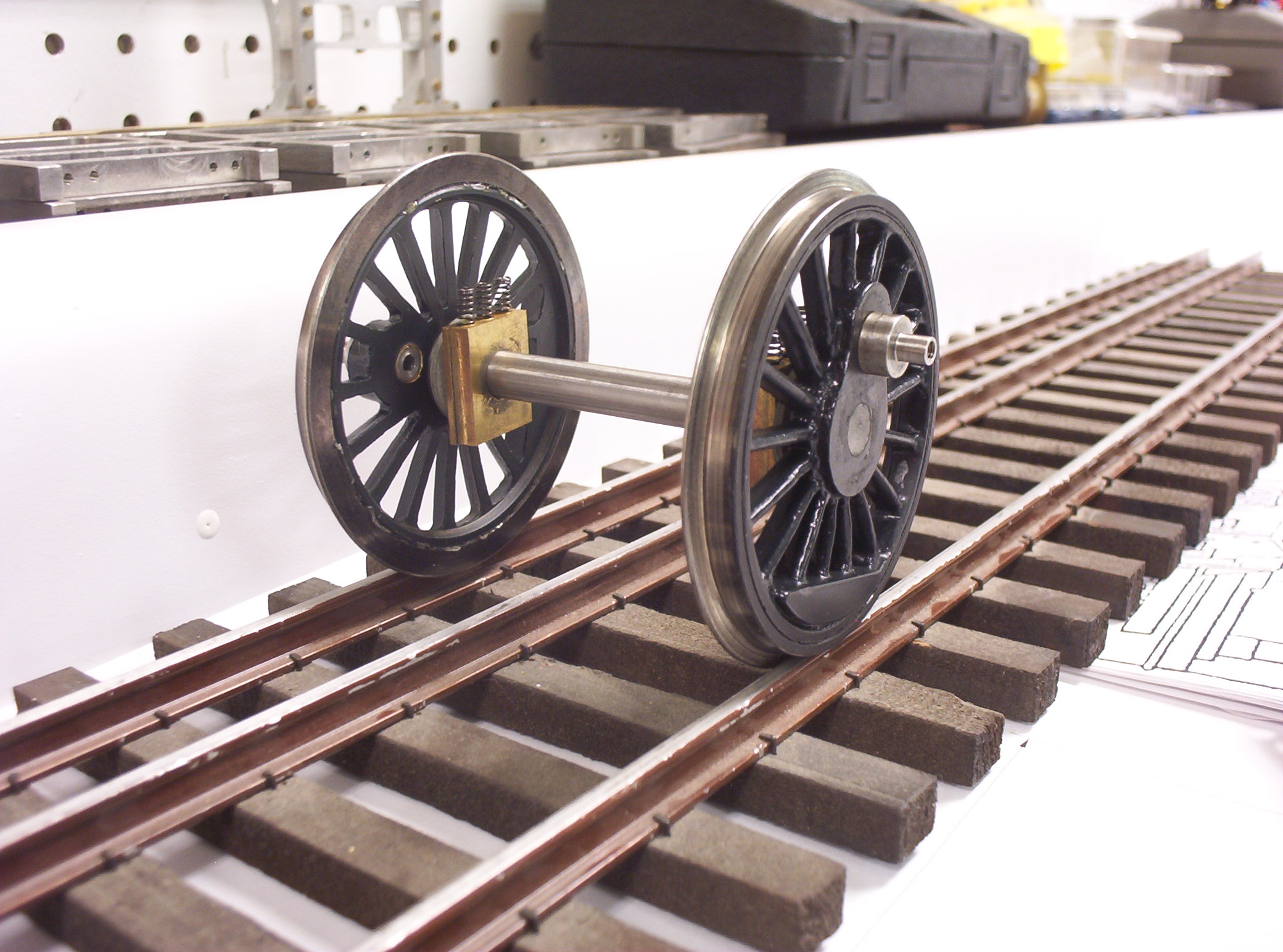
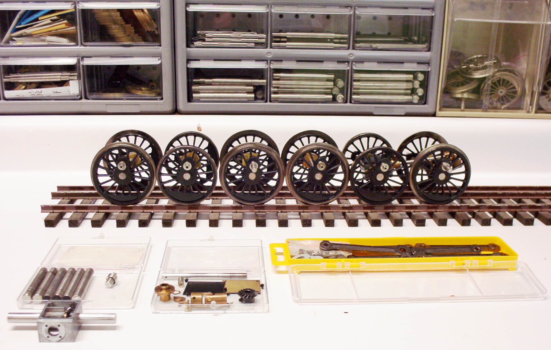
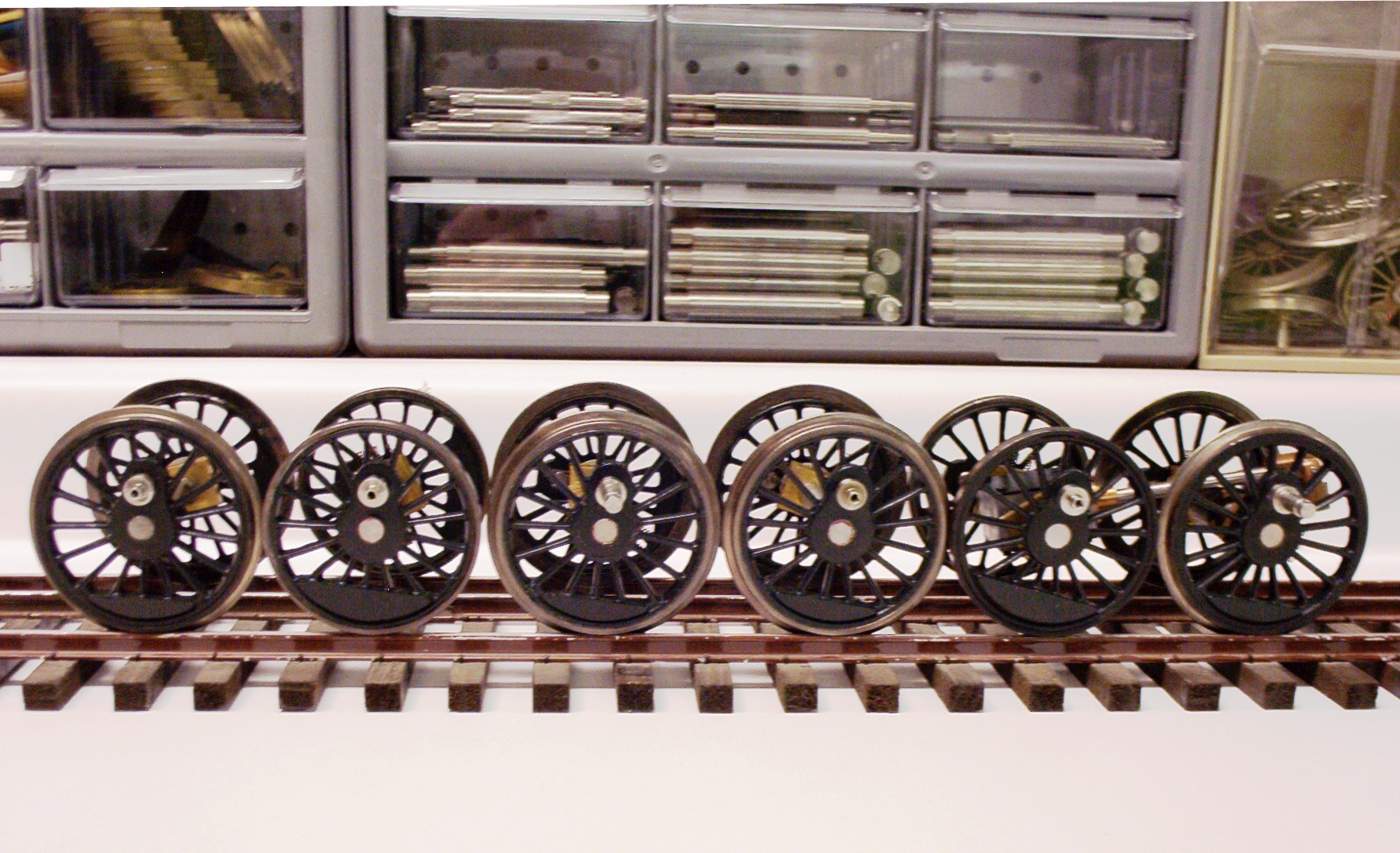
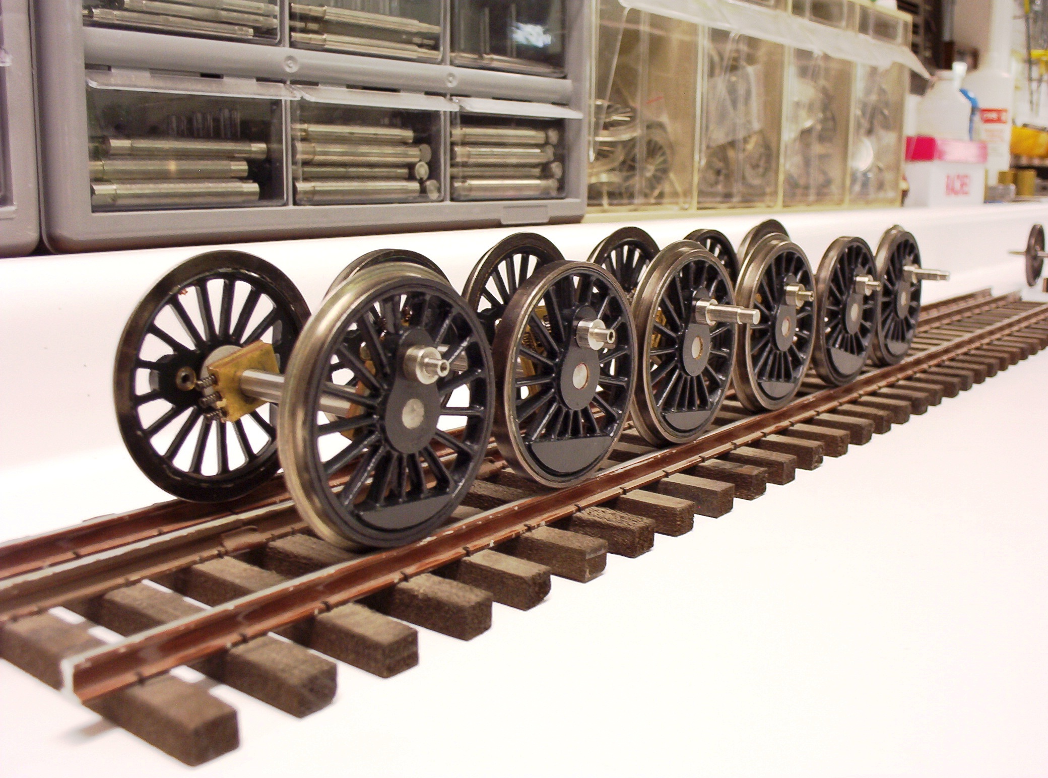
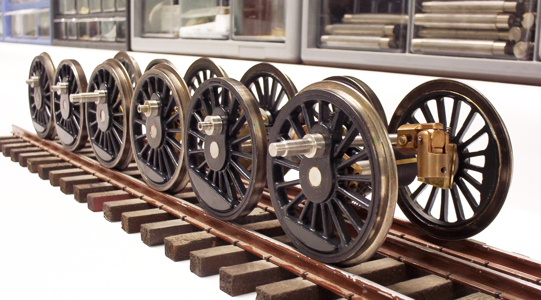
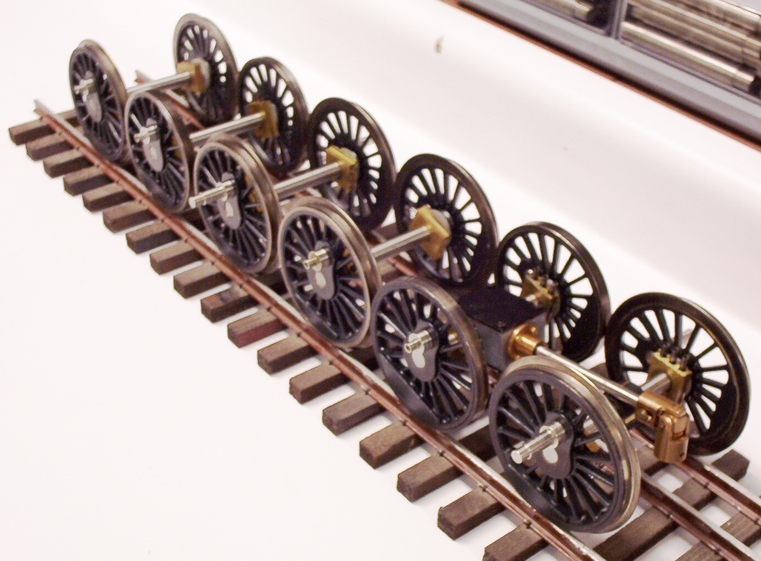
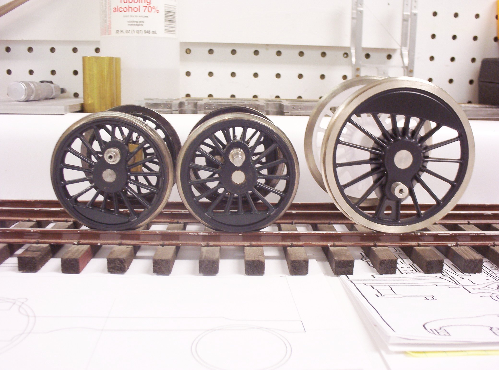
Assembling The Regauged Drivers The first two drivers were regauged and assembled in my shop during the fall of 2008. The last four were completed during the first week of February 2009. The last photo (bottom right) compares the size of the regauged 55" drivers to a 73" driver used on my Southern Railway Ps-4 pacific. The two photos which precede it show a spare set of blind drivers which I regauged for my own use (along with an Accucraft K4 sound cam).
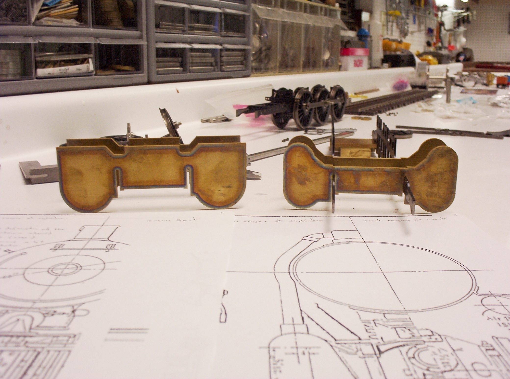
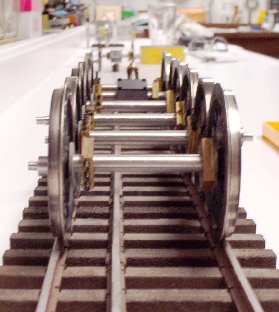
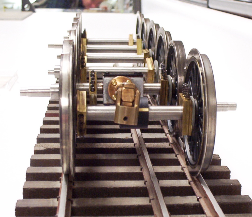
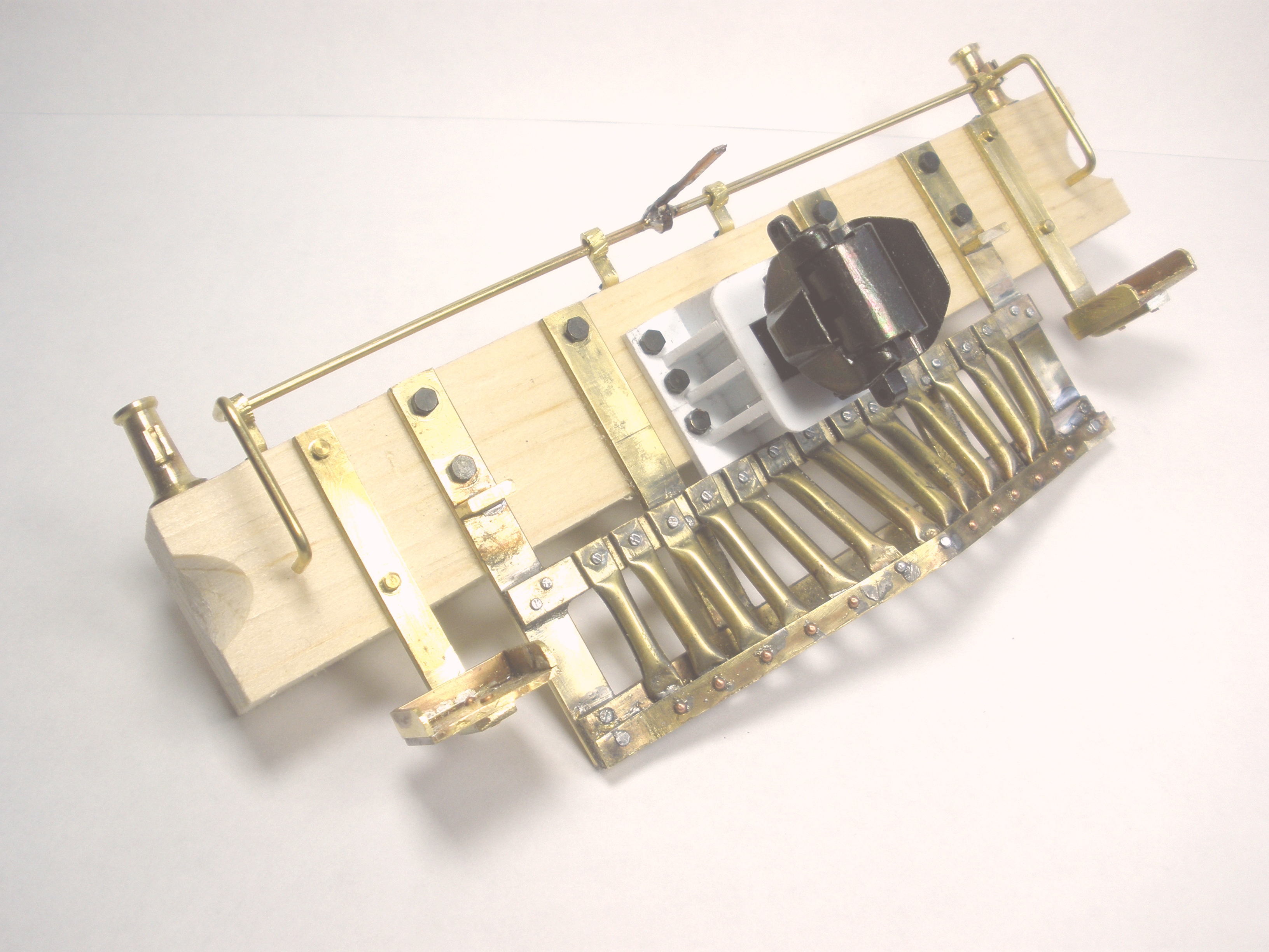
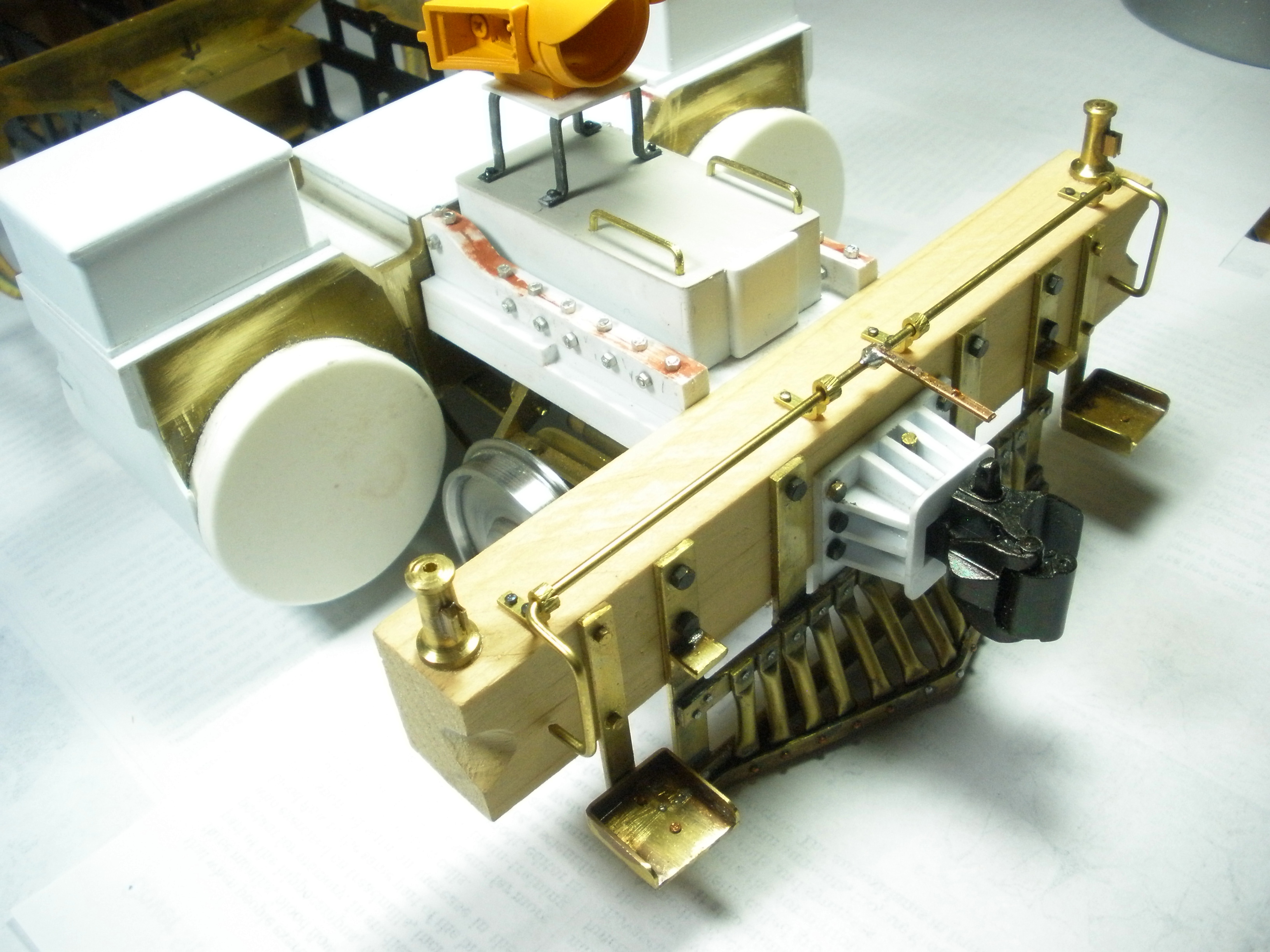
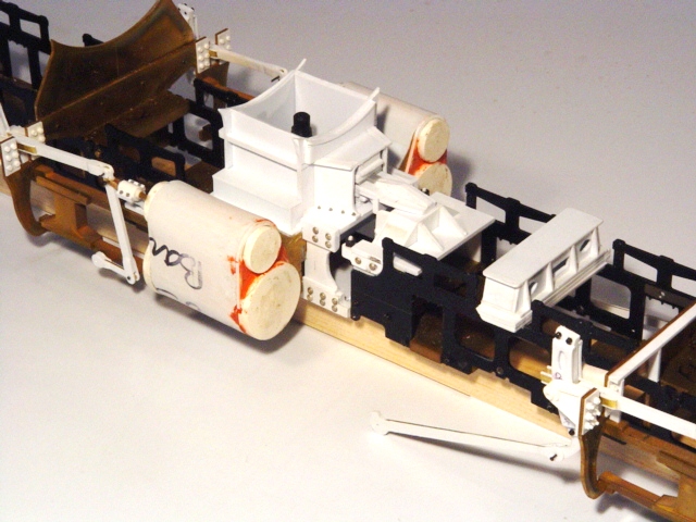
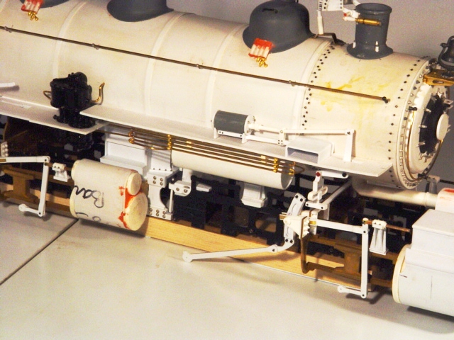
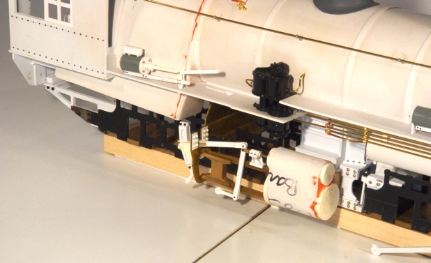
Assembling the Chassis As of October 2008, George had made good progress on getting his locomotive together. He had scratchbuilt his own wood and brass pilot and assembled the various bits and pieces of his regauged frames (first four pics below). By January of 2009, the chassis and its composite styrene and brass valve gear were together, the unique (and as close to prototypical as possible) articulated connection between the high and low pressure engines had been made, and the whole chassis readied for mounting to the boiler and cab assembly. All that remains is mounting the re-gauged drivers into the frames, finishing the main and side rods, and mounting the Pittman motor to the rear high pressure engine.
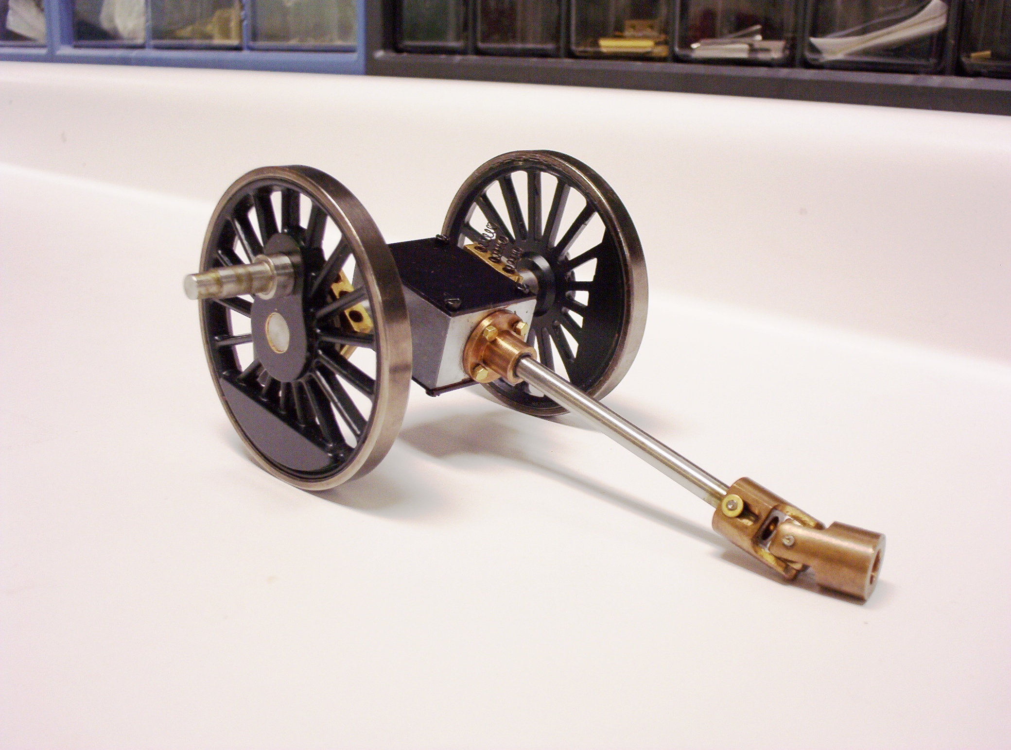
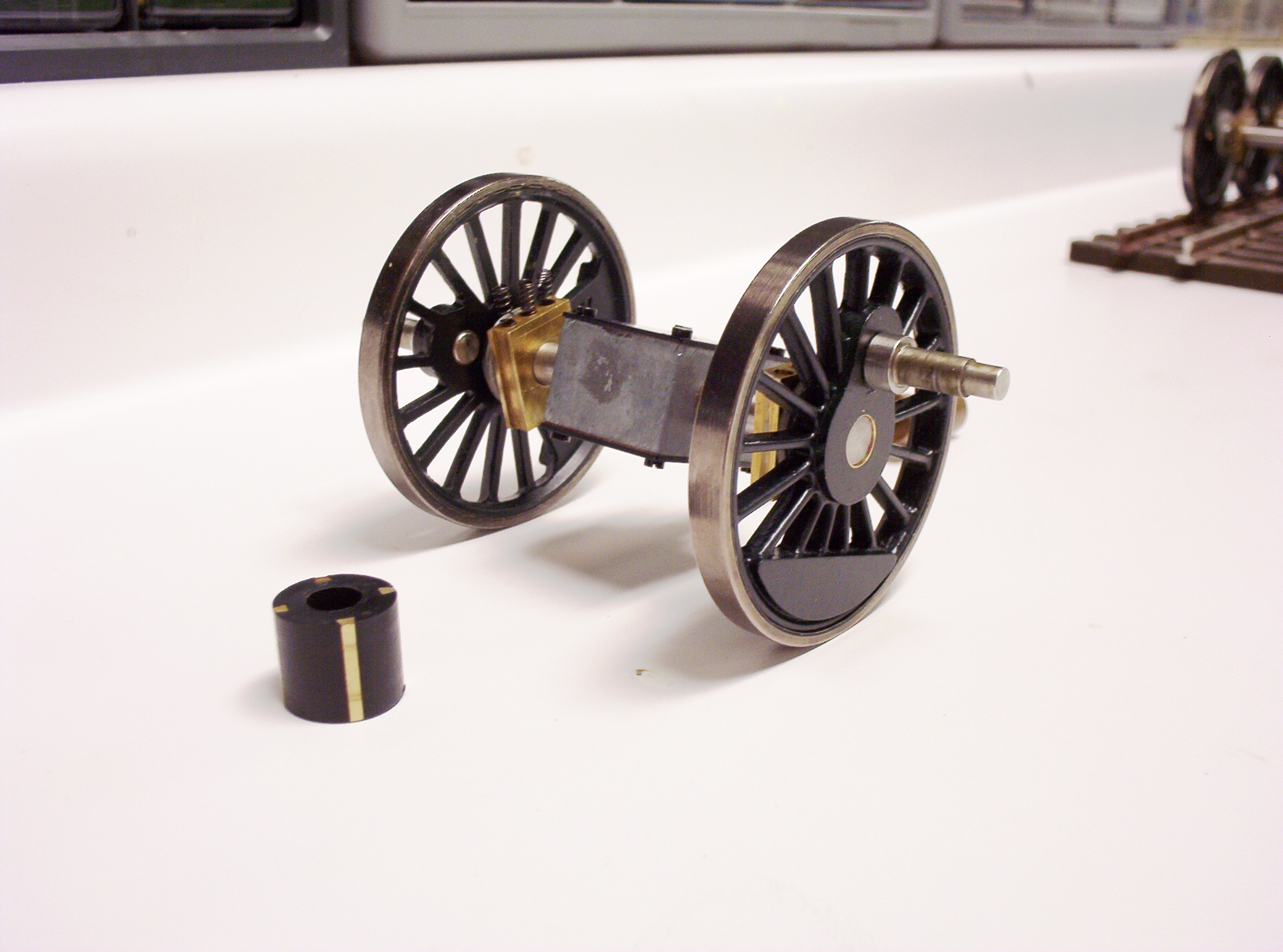
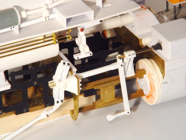
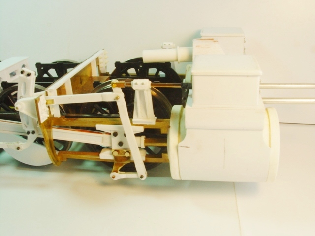
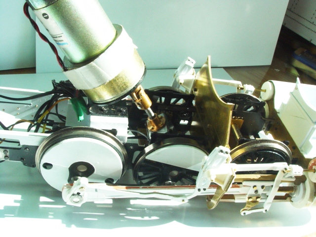
As of late February 2009, George had mated the re-gauged Accucraft K-4 drivers to the frames and attached the original K-4 side rods to them as well as his own scratchbuilt styrene main rods and valve gear. Since one of the Accucraft K-4 drive trains was to be reused, only the rear set of drivers are powered; and at that, the gearhead motor is mounted at a sharp angle in order to hide it in the firebox area. George writes about this part of the project:
Here are some specs. on the shaft cutting,
etc: The overall length of the gear box with shaft is now 3 1/4" Of
this, the gear box itself is 1 9/32" long, the end collar is 3/8"
and the rest is the shaft, some 1 3/32". Also, the shaft on the end
of the motor was cut down by 1/4" and a new flat was cut onto the
shorter shaft. That leaves 1/2' in the center of the coupling
(U-joint). I had to alter the frame spacer that sits directly under
the motor to allow the motor to pivot upright enough to be mounted
at this angle. With the motor mounted as it is, there is about 1/4"
of clearance between the motor and the inside of the boiler top, and
the motor and the inside of the rear of the firebox.
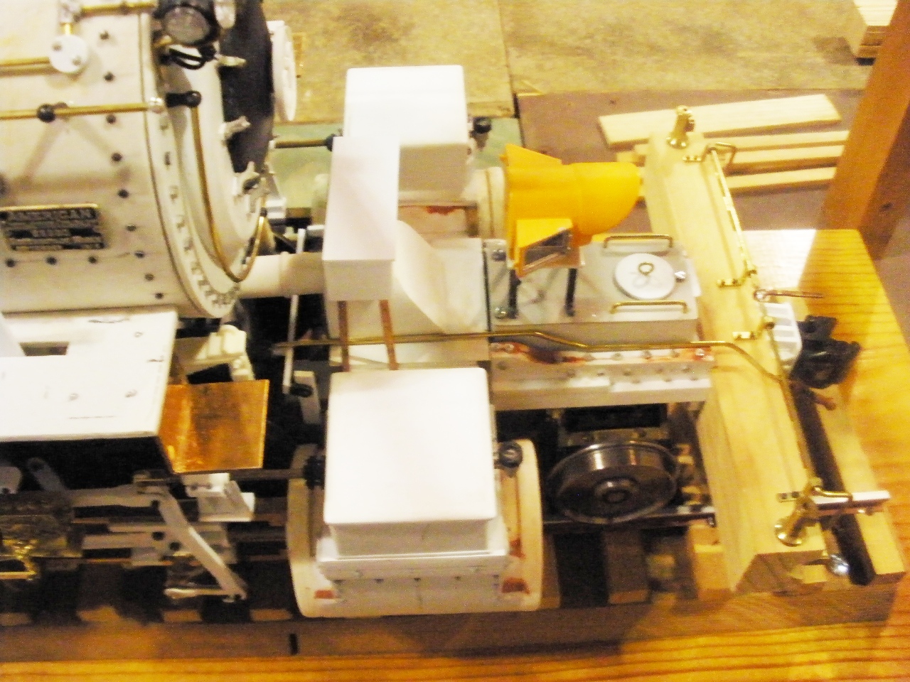
George has built his engine to include
"working" lubricators (and if he could find scale grease, George
writes that he would find a way to pump it!). Most of George's work
on the locomotive between February and May of 2009 has been on
detail parts, the little bits and pieces that transform a spartan
toy into a scale model. Among some of these parts are scratchbuilt
leaf springs, brake hangars, brake shoes, ash pans, steam pipes,
exhaust steam injector, and more!
|
|
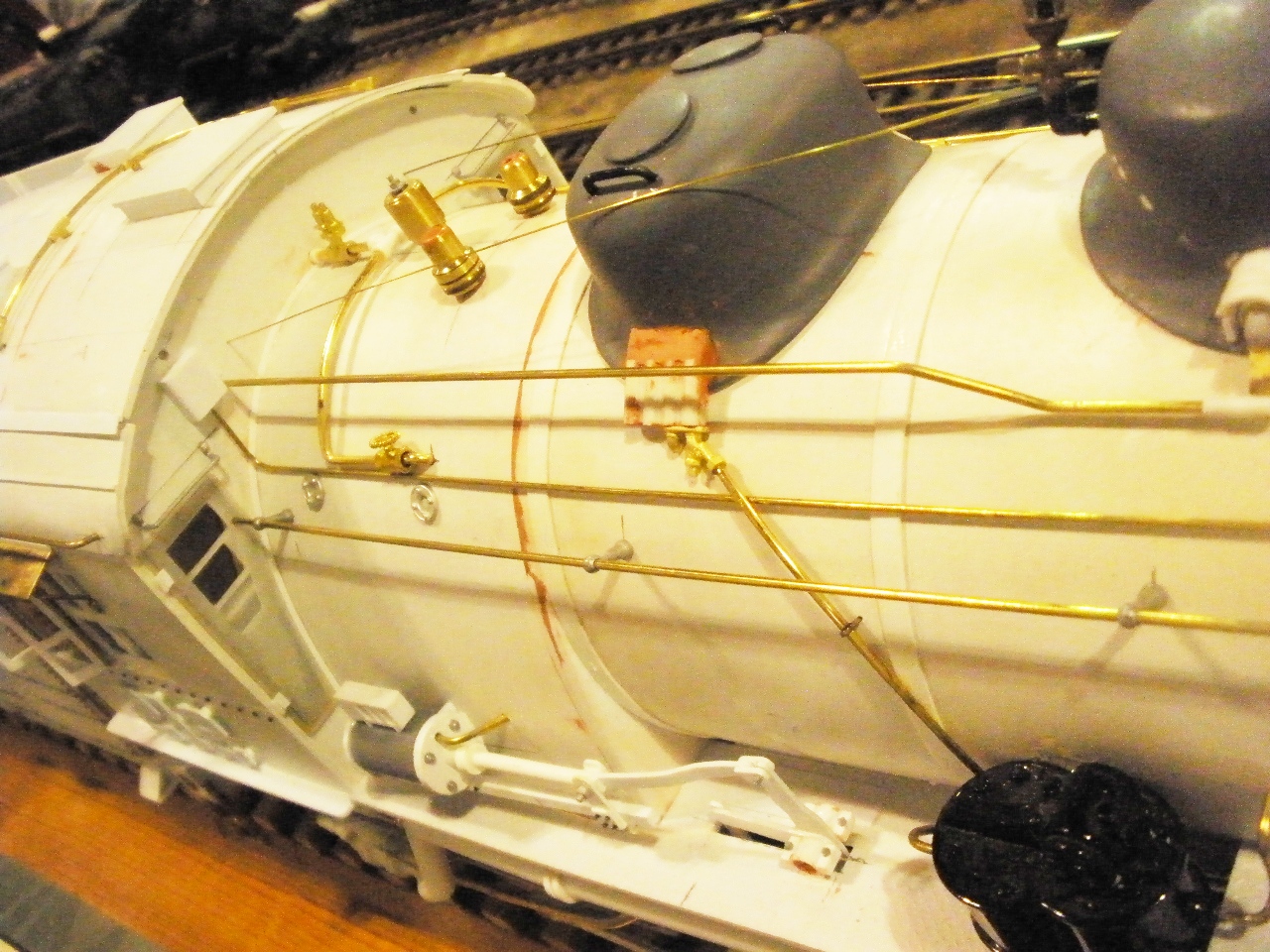
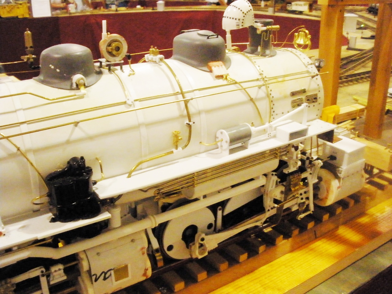
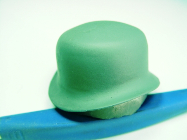
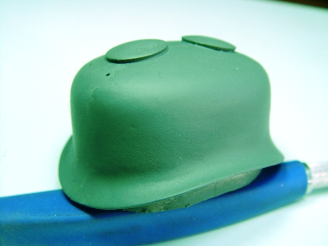
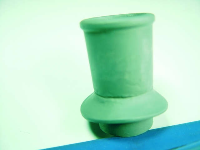
Boiler & Cab In 2007 George created patterns for the domes and stack on his D&SL mallet. These he copied in urethane. The boiler, as per the same techniques that Barry Bogs uses, is a styrene tube, likewise the cab, with Peco track nails to simulate rivets.
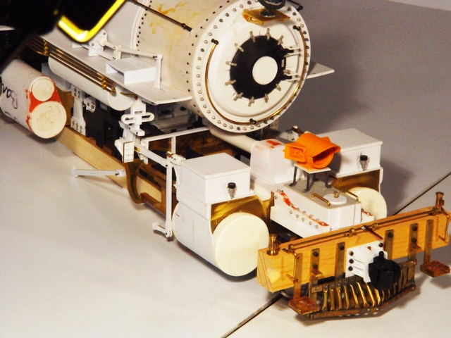
During April 2009 George was working on the numerous boiler and cab details. He writes: I am working on the confounded heater pipe for the passenger cars, which wends its way all over the right side of the loco from front to back, BUT before one does the pipe, one needs to do the ash pans, BUT before one does the ash pans one should place rivets on the bottom of the firebox, BUT before one places the rivets, one should build the attachment points for the ash pans, BUT before doing the attachments, one should place the "cheek" weights that are in the lower sides of the firebox, BUT..............I think you are getting the picture. All these things should be done today, I also then wish to build the rest of the cab windows (sliders, etc) armrests, and the front doors. Of particular interest are the Magnus and Nathan non-lifting injectors which George made from scratch. The early, large generator was made by adding a scratchbuilt turbine to a modified Accucraft casting. By May of 2009, George was nearing completion of all the locomotive's electronics. He writes:
The model now has ALL the wiring necessary installed. That includes
the sound system, cuff gating, back-up light, markers (scratch built
using a jewelry bead) and front headlight. The circuit board for the
lights is in the front part of the boiler, so wiring had to be run
all the way back to the motor, and then forward through both engines
to the light! Fussy work. |
|
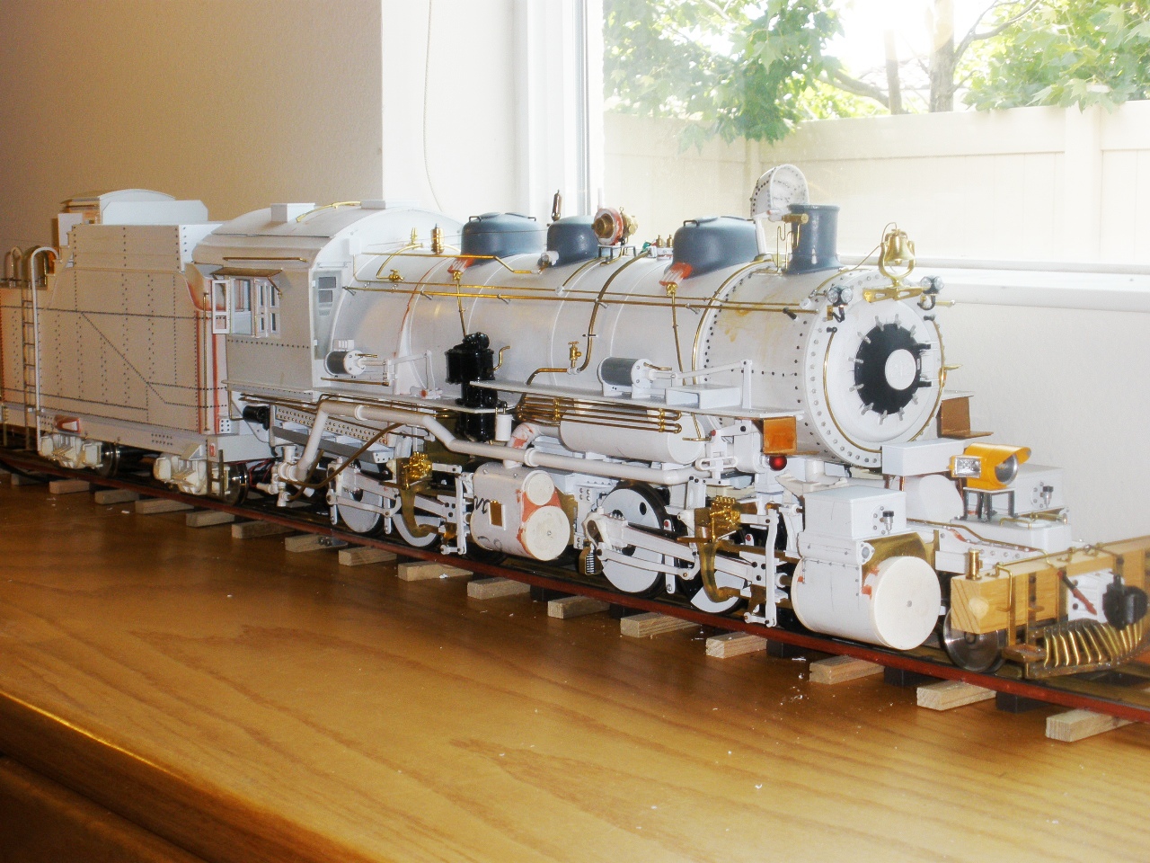
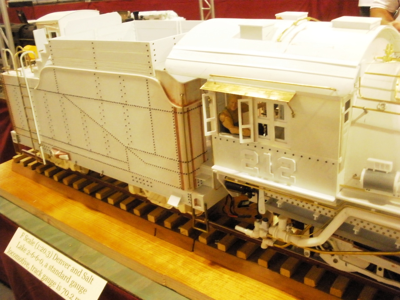
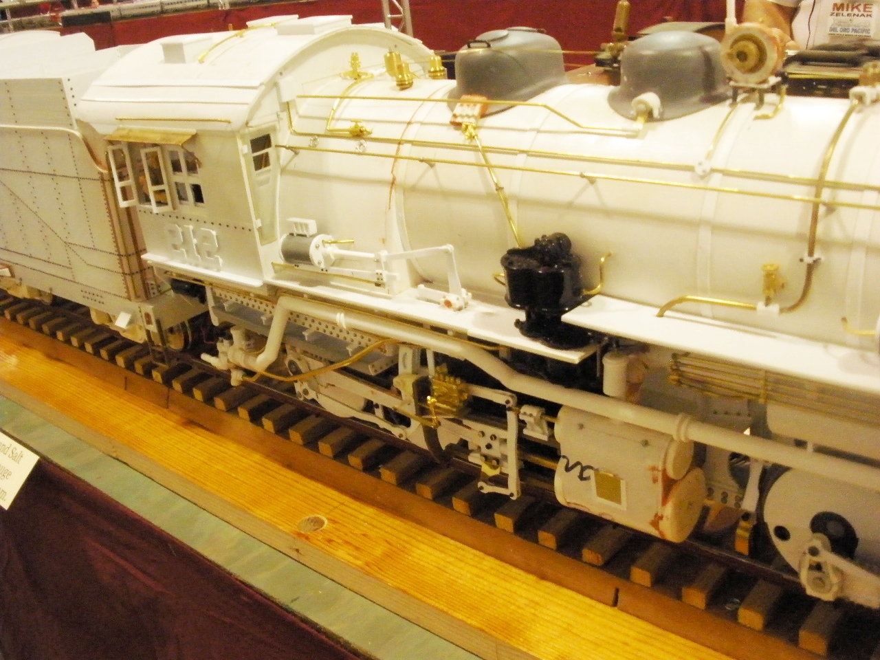
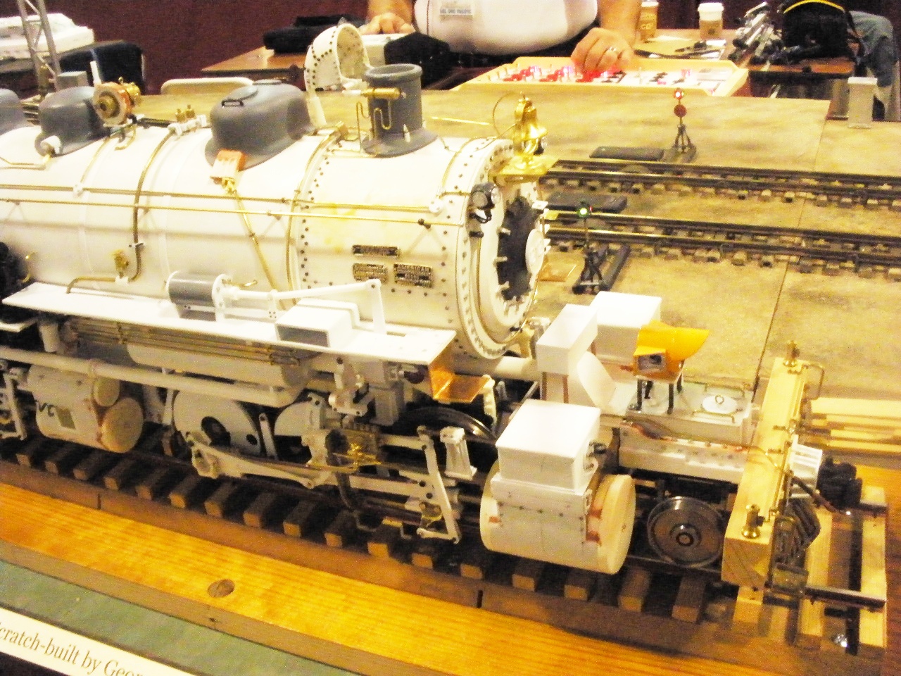
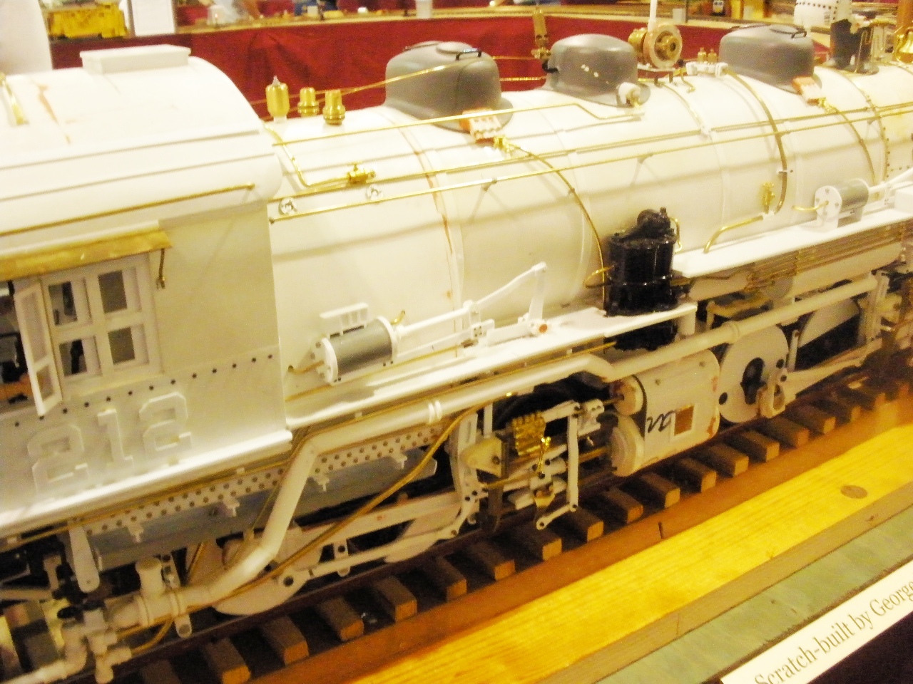
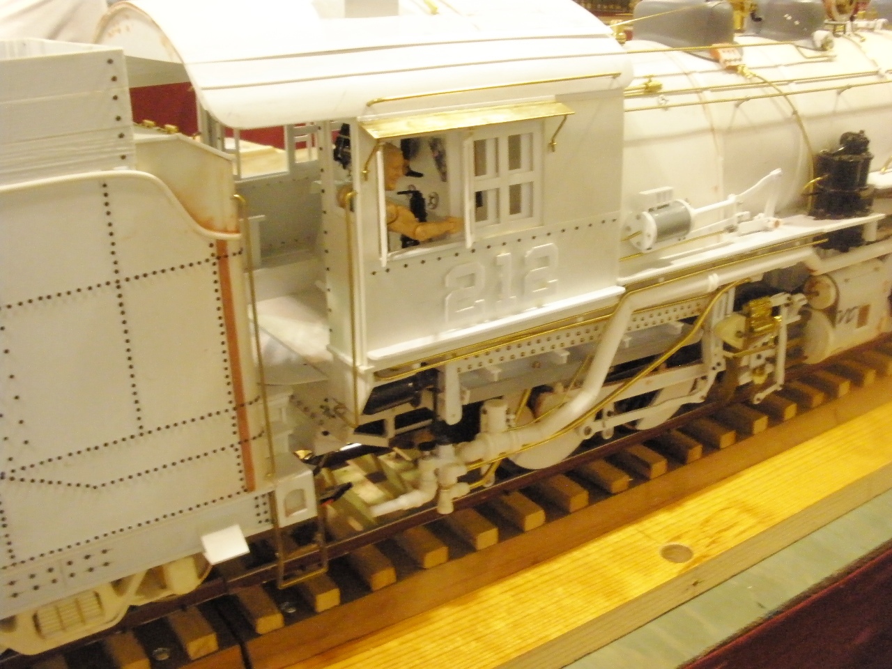
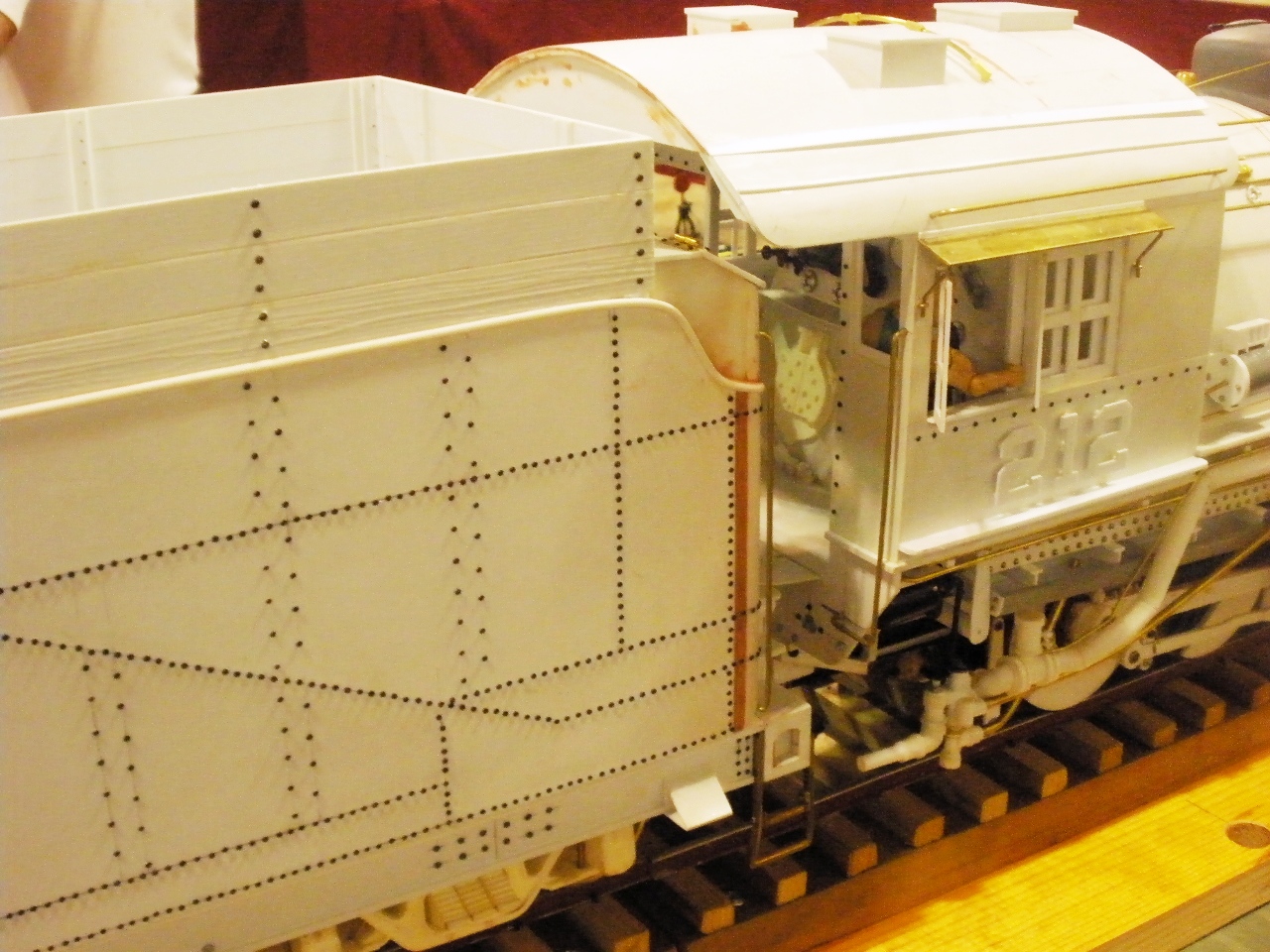
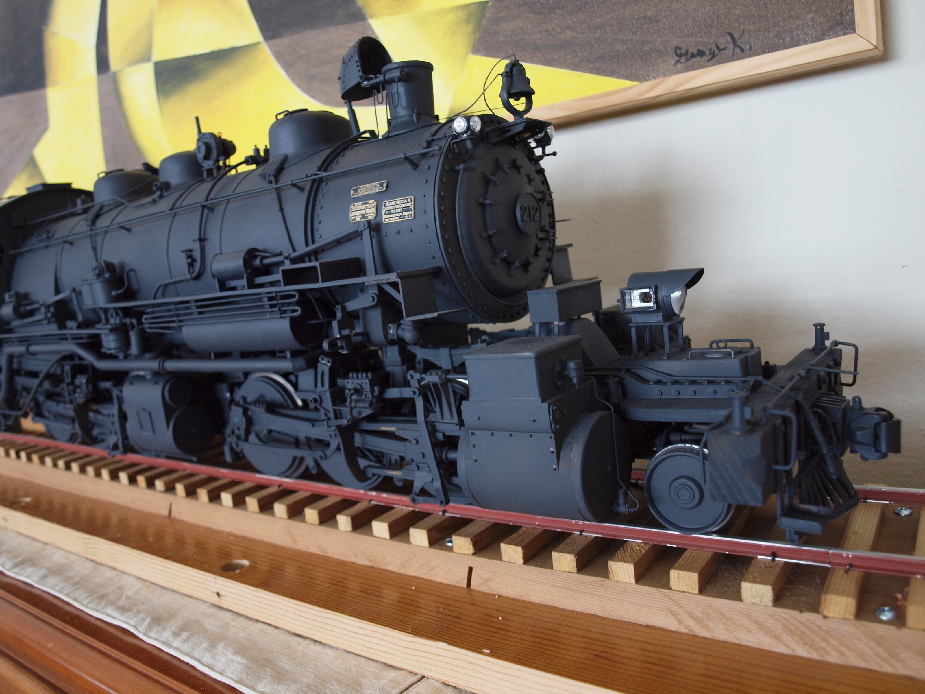
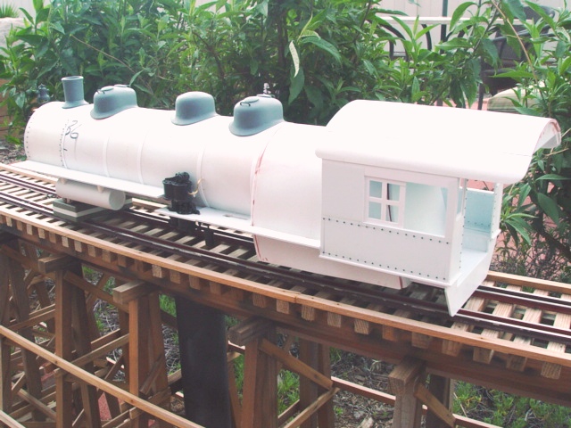
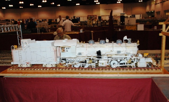
The Completed Locomotive Over the weekend of June 6-7, 2009, George exhibited the completed D&SL mallet #212, sans paint, at the Big Train Show in Southern California:
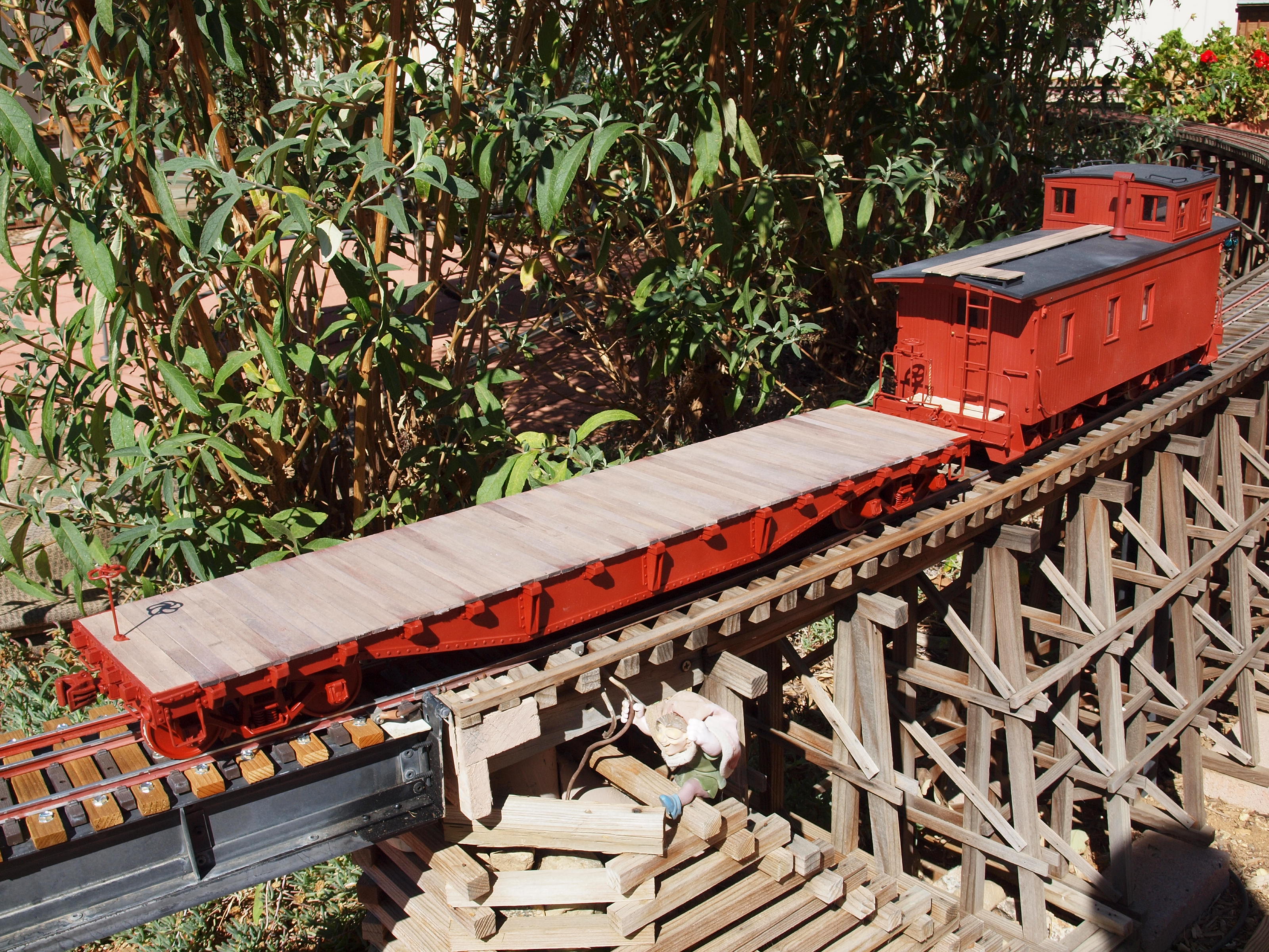
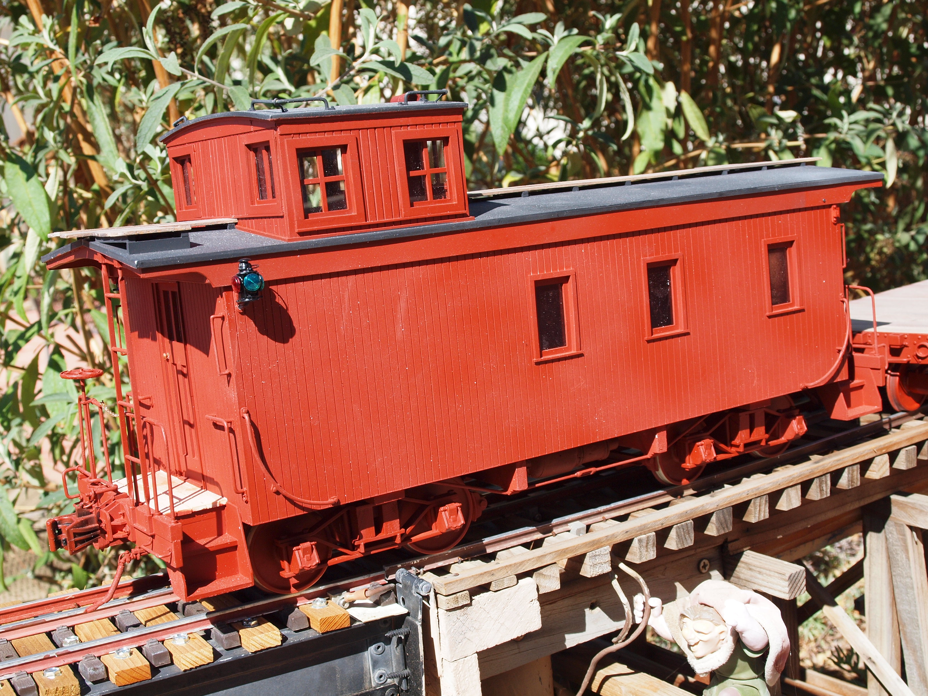
As of October 2009, George has the D&SL mallet painted and lettered. George has also built some 1/20th scale freight cars to go with his mallet:
|
|
Last update: 29 October 2009
|
|
Copyright 2004-2009 CumberlandModelEngineering.com. All Rights Reserved |
.jpg)
 D&SL
2-6-6-0:
D&SL
2-6-6-0: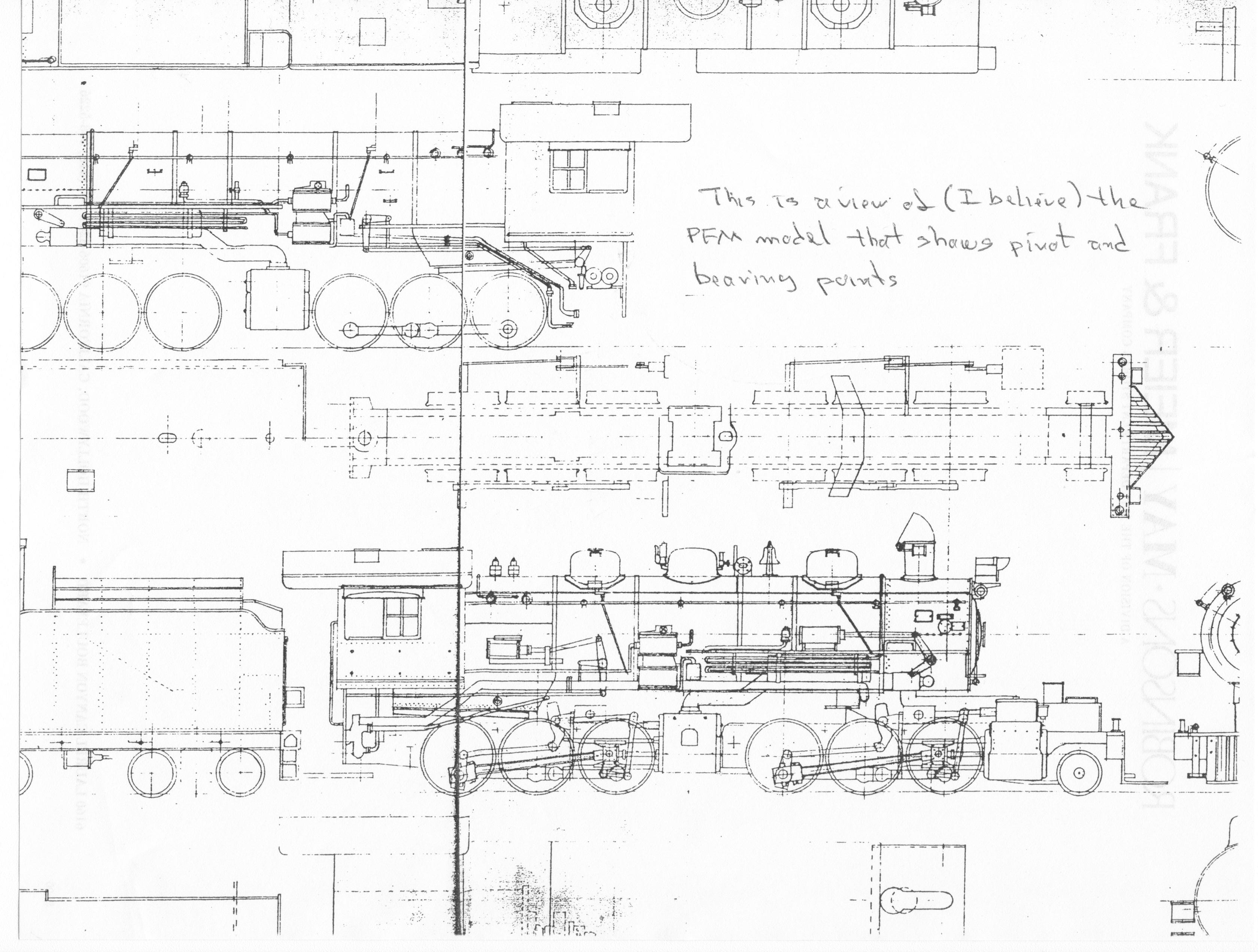


.JPG)
.JPG)
.JPG)

%201.JPG)
%202.JPG)
%203.JPG)
.JPG)


.JPG)

.jpg)

.JPG)
.JPG)
.JPG)
.JPG)
.JPG)

.JPG)
.JPG)
.JPG)
.JPG)
.JPG)
.jpg)