.JPG)
"Your source for standard gauge modeling in 1:20.3"
|
|
|
"Your source for standard gauge modeling in 1:20.3" |
|
|
.jpg) |
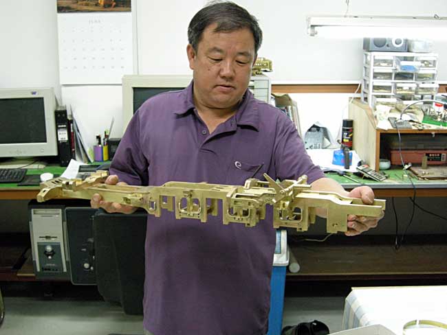
Doug Hemmeter (at left with his wife Mary) is a marine engineer hailing from the Houston area; and over the last several years he has begun to distinguish himself as first a kitbasher of Fn3 locomotives--most notably with a series of D&RGW C-25s based upon the Bachman 2-8-0 drive, built with an all new boiler, cab and tender--and now as a scratch-builder of standard gauge locomotives in F scale. His series of D&RGW M-68 4-8-4s are his first foray into standard gauge. As of November 2011 he has completed two standard gauge 4-8-4s with two more close behind. What comes next: The D&RGW L-105 Challenger, big UP steam, and a C&O 2-10-4. Doug may be contacted at whemmeter@sbcglobal.net and at wdh_marine@sbcglobal.net |
.jpg) |
|
Doug's model of the L-105 represents the first batch of locomotives produced by Baldwin in January of 1938. They are different from the second batch (#3710-3714 arriving on the property in early 1942) with their Baldwin Disc drivers (the later engines had boxpoks) and prominent Elesco feedwater heaters. These Baldwin built challengers were well suited to the Grande's mountainous profile, developing 8,000 lbs more tractive effort than their lighter, Alco designed cousins on the Union Pacific. With the construction of the L-105 4-6-6-4, Doug has achieved another first in F scale: The first 1:20.3 standard gauge articulated locomotive. Well done, Doug! With A Little (More) Help From My Friends Having friends to contribute to a project as complex as a 1:20.3 scale standard gauge 4-6-6-4 makes all the difference in world. In the first place, Doug has the singular good fortune of a patron, Mr. Gary Bartlow, who commissioned the building of the L-105 as well as the four M-68 models. Gary now has the singular distinction of owning the most standard gauge models in F scale of anyone in the country. We hope to see Gary building a layout soon to run these monsters on! So far, eight different people are at work on or have contributed components to the L-105: |
|
|
● Dave Queener of Cumberland Model Engineering (your host) is responsible for machining and assembling the 70" drivers, main & side rods, construction of the four wheel lead truck and initial CAD work on the L-105's lead engine unit. |
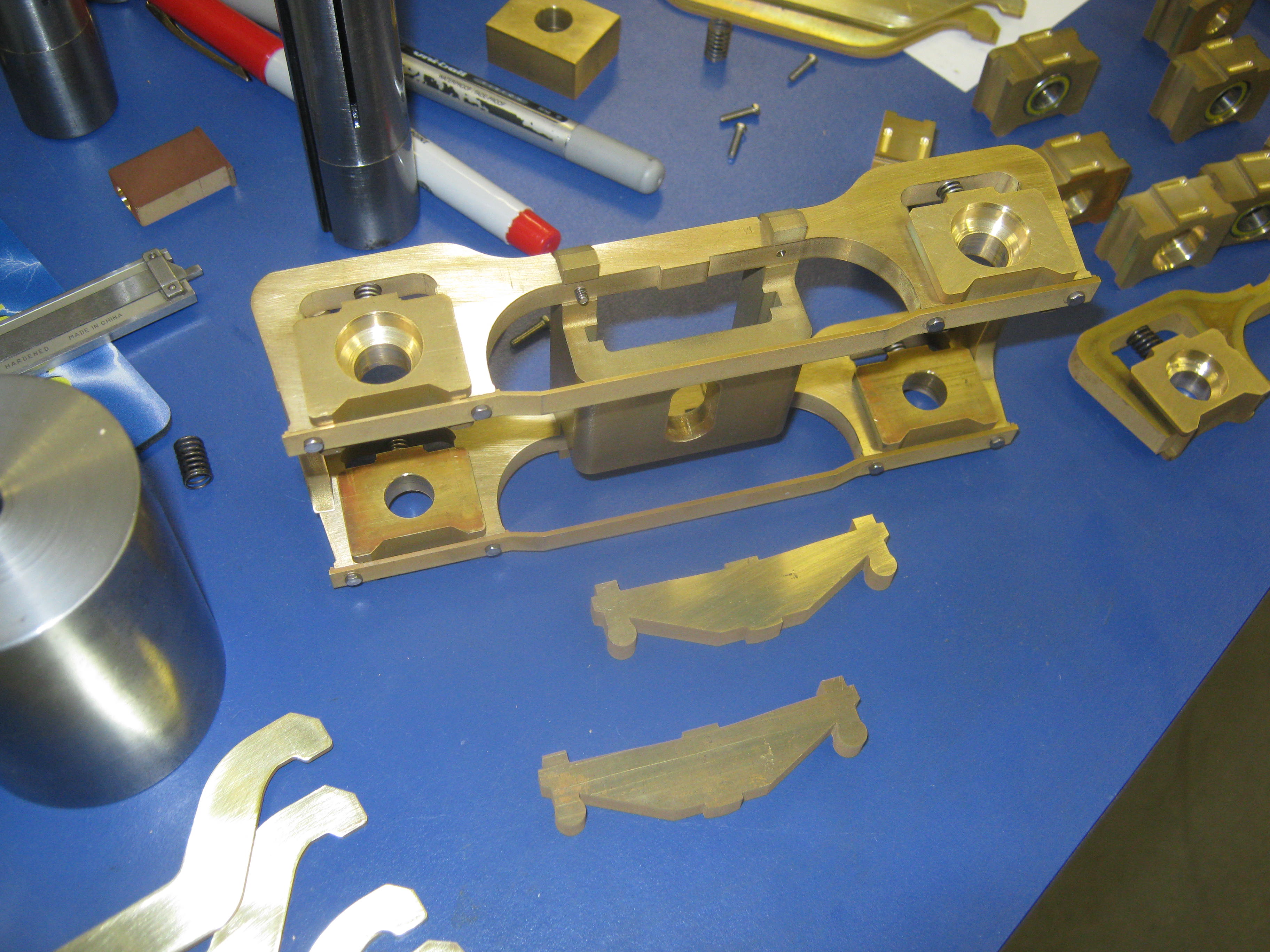
● Michael Aronson is drawing the remainder of the chassis in CAD and providing both the bearing boxes as well as the frame's pedastal binders in cnc machined brass. |
| ● Bill Brisko of Pacific Locomotive Works provided additional Baldwin Disc driver center castings, same as were used on the D&RGW M-68. Bill also provided 36" and 42" steel wheels for the lead & trailing trucks. | ● Rodney Eddington of R and K Railroad Products will be milling the frames and assembling the chassis. |
| ● Ward Hammond has laser cut the cab and tender sides from styrene. | ● Barry Olsen of Barry's Big Trains has provided the double reduction gearboxes (four per locomotive). |
| ● Barry Bogs is doing the battery, Airwire and sound installation on the L-105. | ● Doug Hemmeter of D&M Railroad Backshop is doing all the rest! |
|
Research Materials
(updated 12-8-11) Drawings for this project have come from several sources: First, Hundman Publishing's The Locomotive Cyclopedia--Volume II (article by Robert L. Le Massena, drawings by David Day) has been quite helpful in giving an overall view. Second, the Colorado Railroad Museum's Richardson Railroad Library provided prototype elevation and section drawing as well as several component drawings: front frame, trailing truck frame, main & side rods, and others. Finally, the lion's share of part drawings is coming from the Denver Public Library's Western History Collection. To these we should add drawings of the distinctive Baldwin disc drivers which were found in a late 1930s era Locomotive Cyclopedia. Additional help has come from a brass O scale model of an L-105 imported years ago by Max Gray. Here's a sample of some of our main resources:
|
|
.jpg) .jpg) 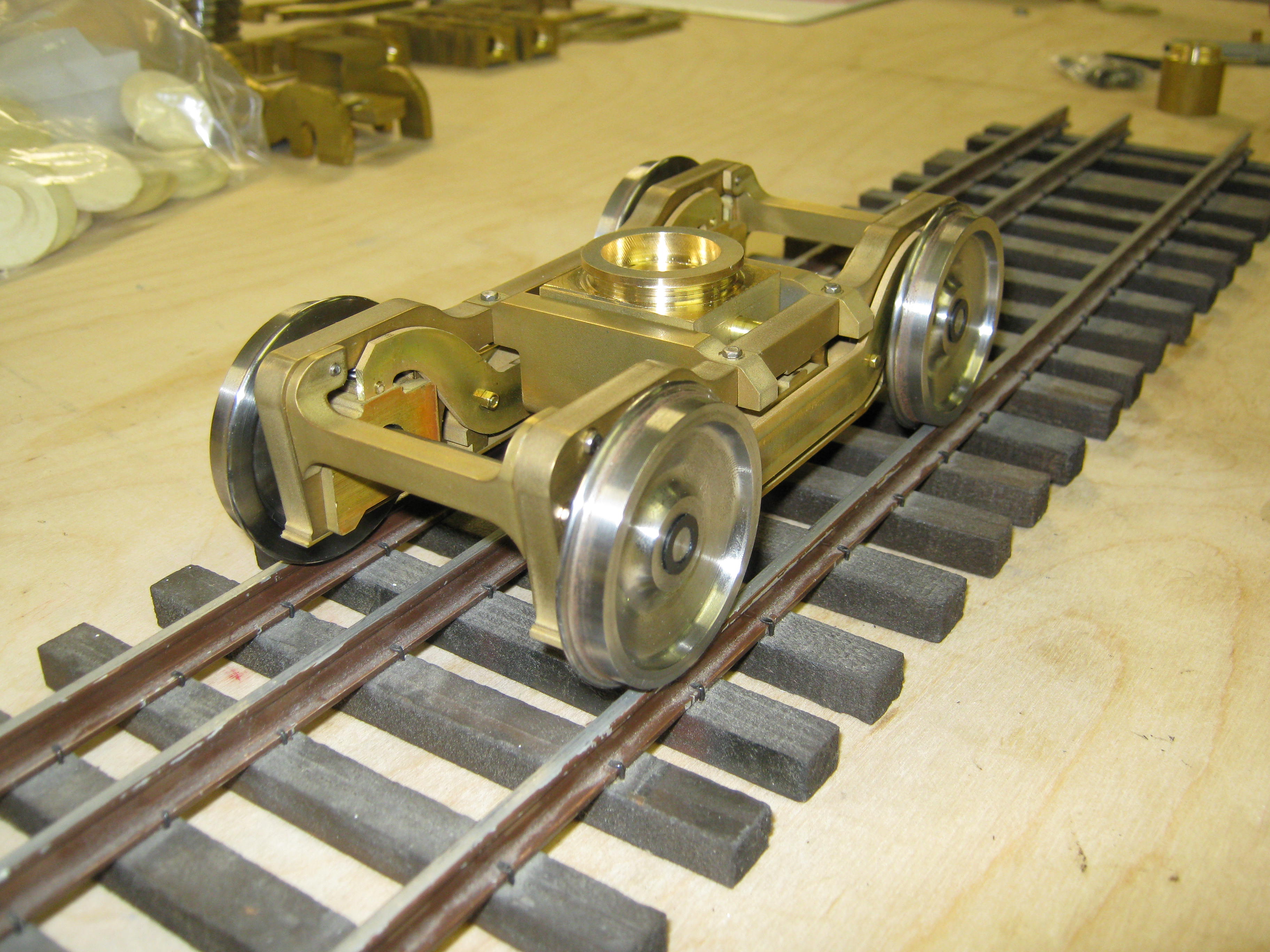 L-105
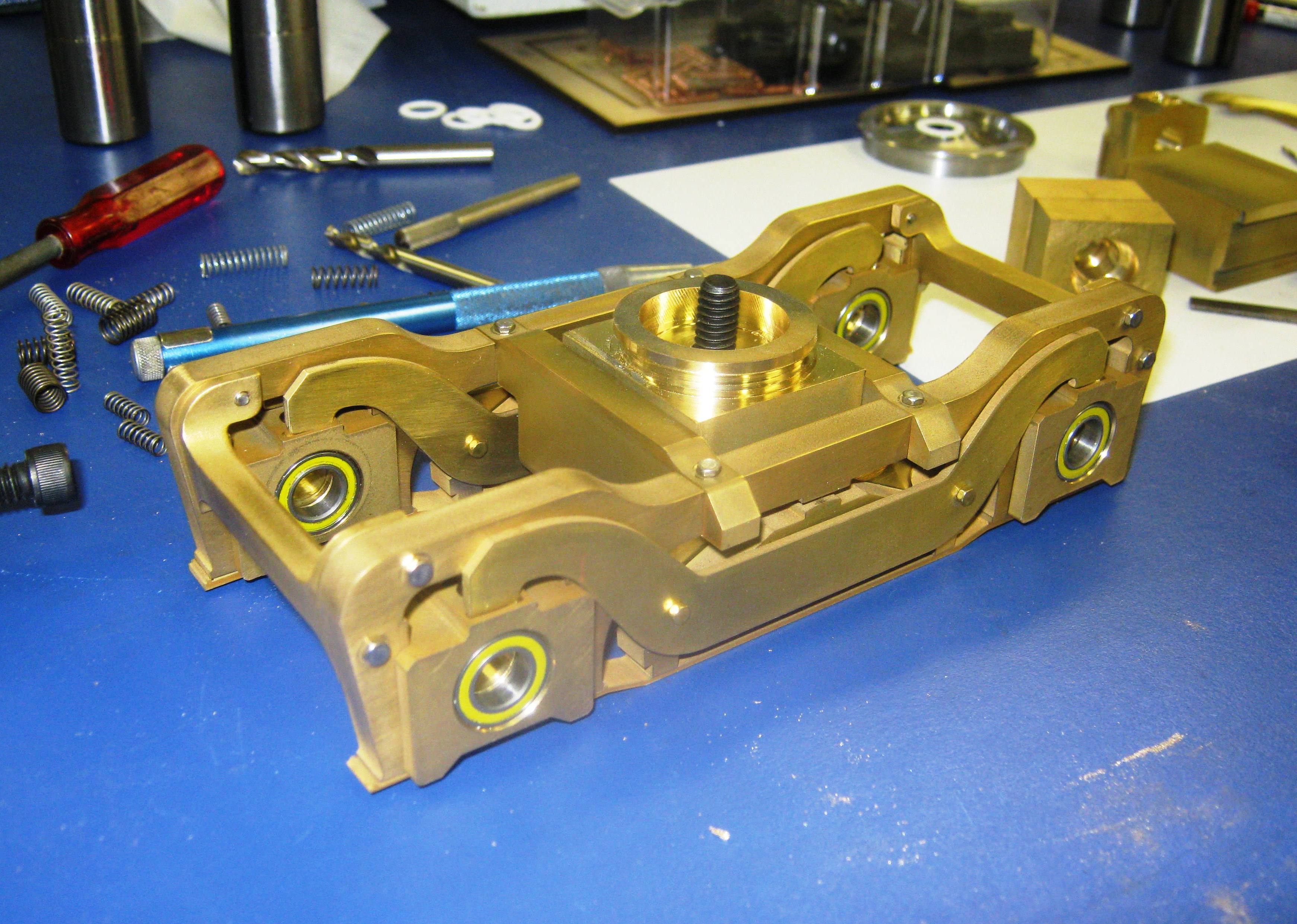
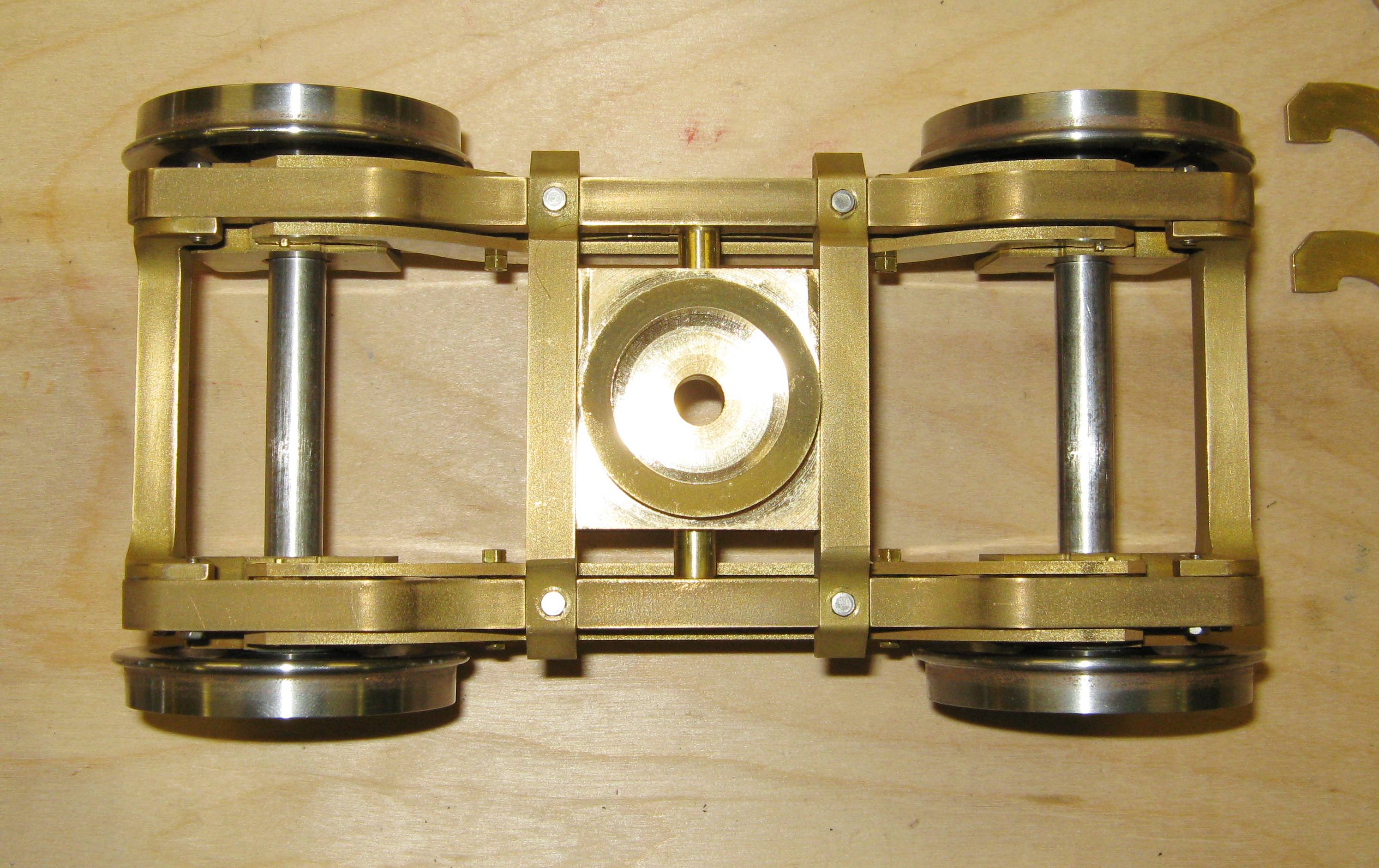
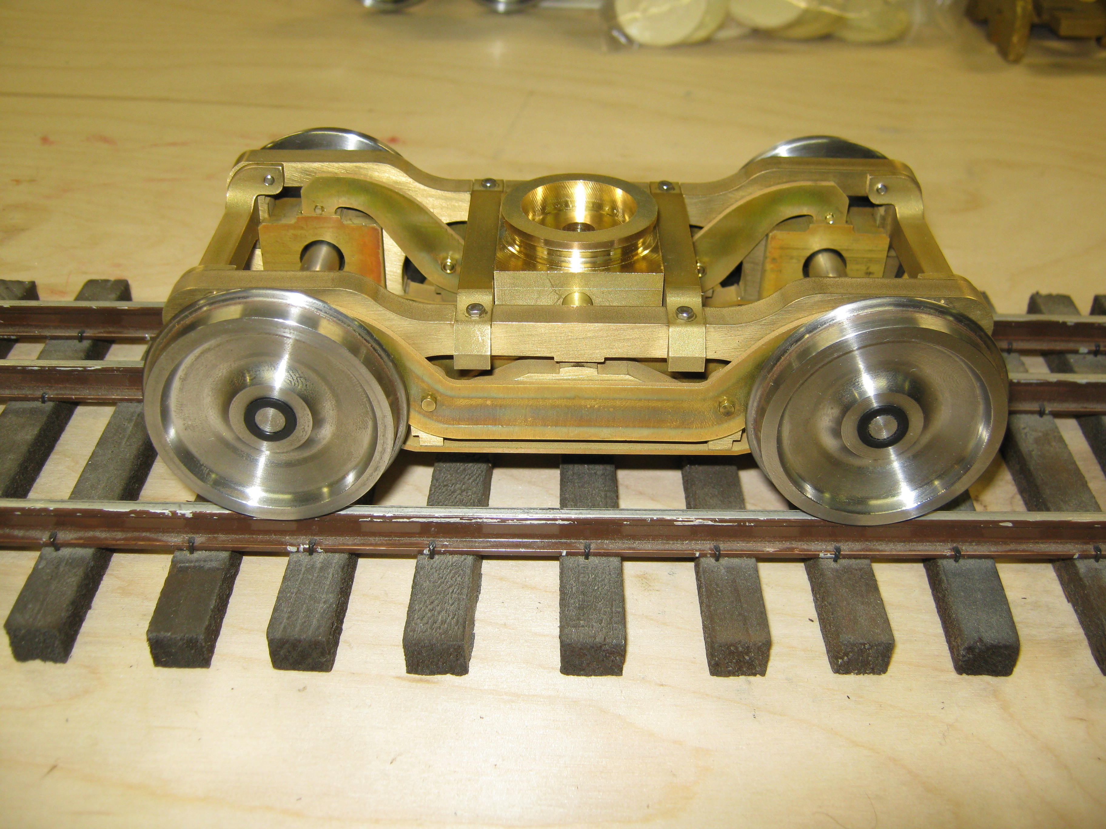
Lead Truck Completed
(updated 2-22-11) L-105
Lead Truck Completed
(updated 2-22-11)
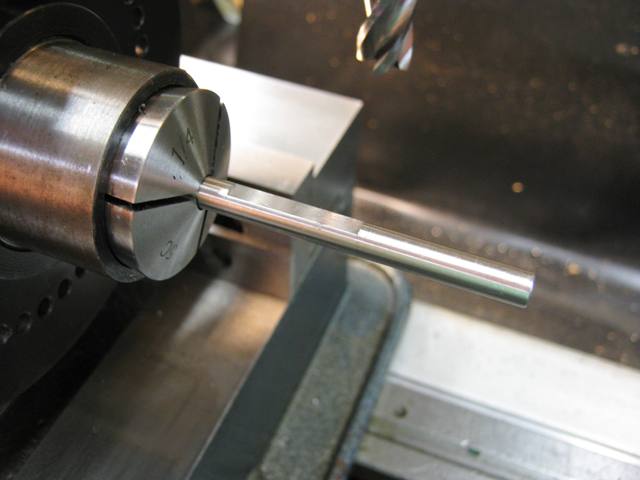
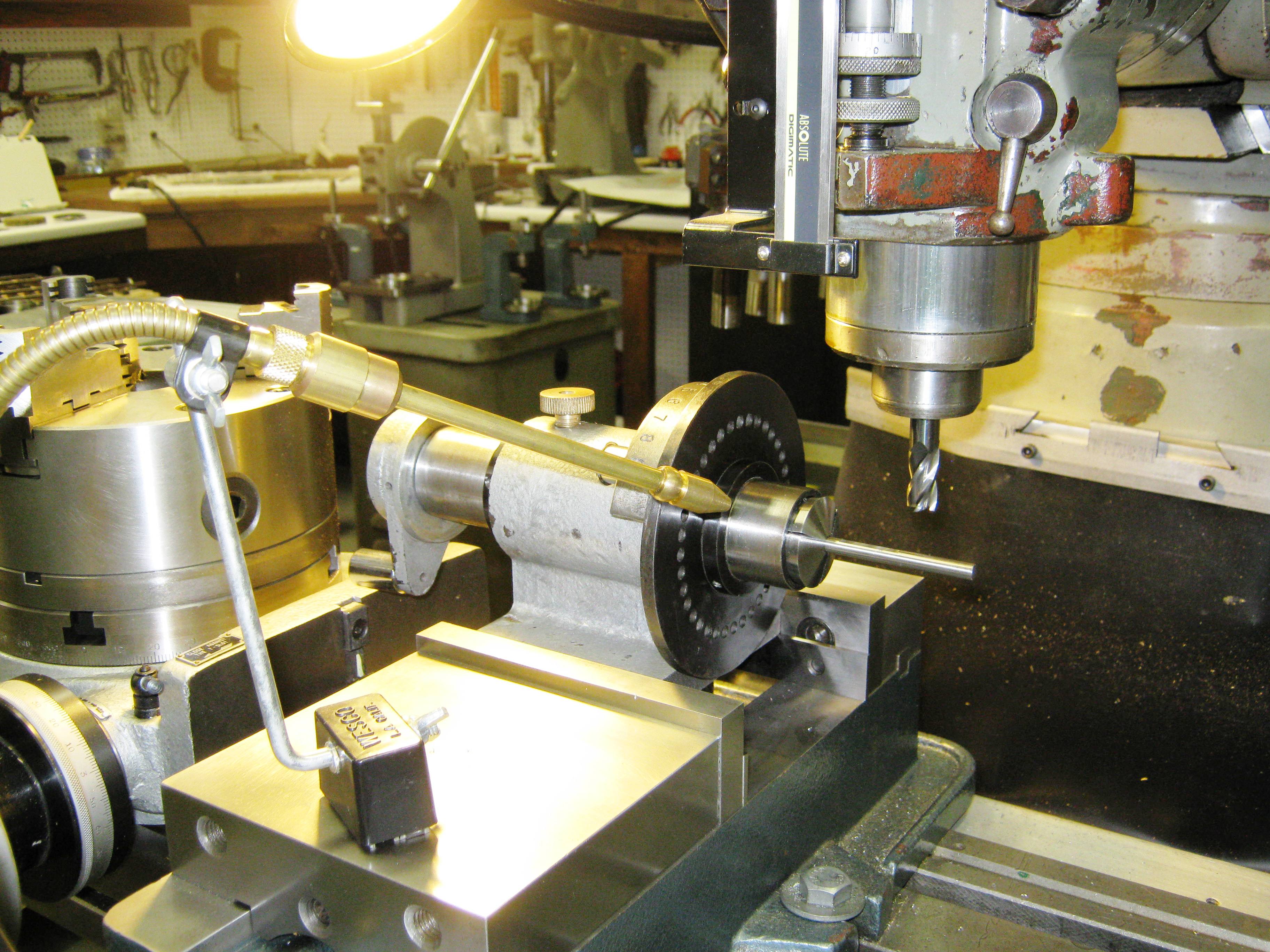
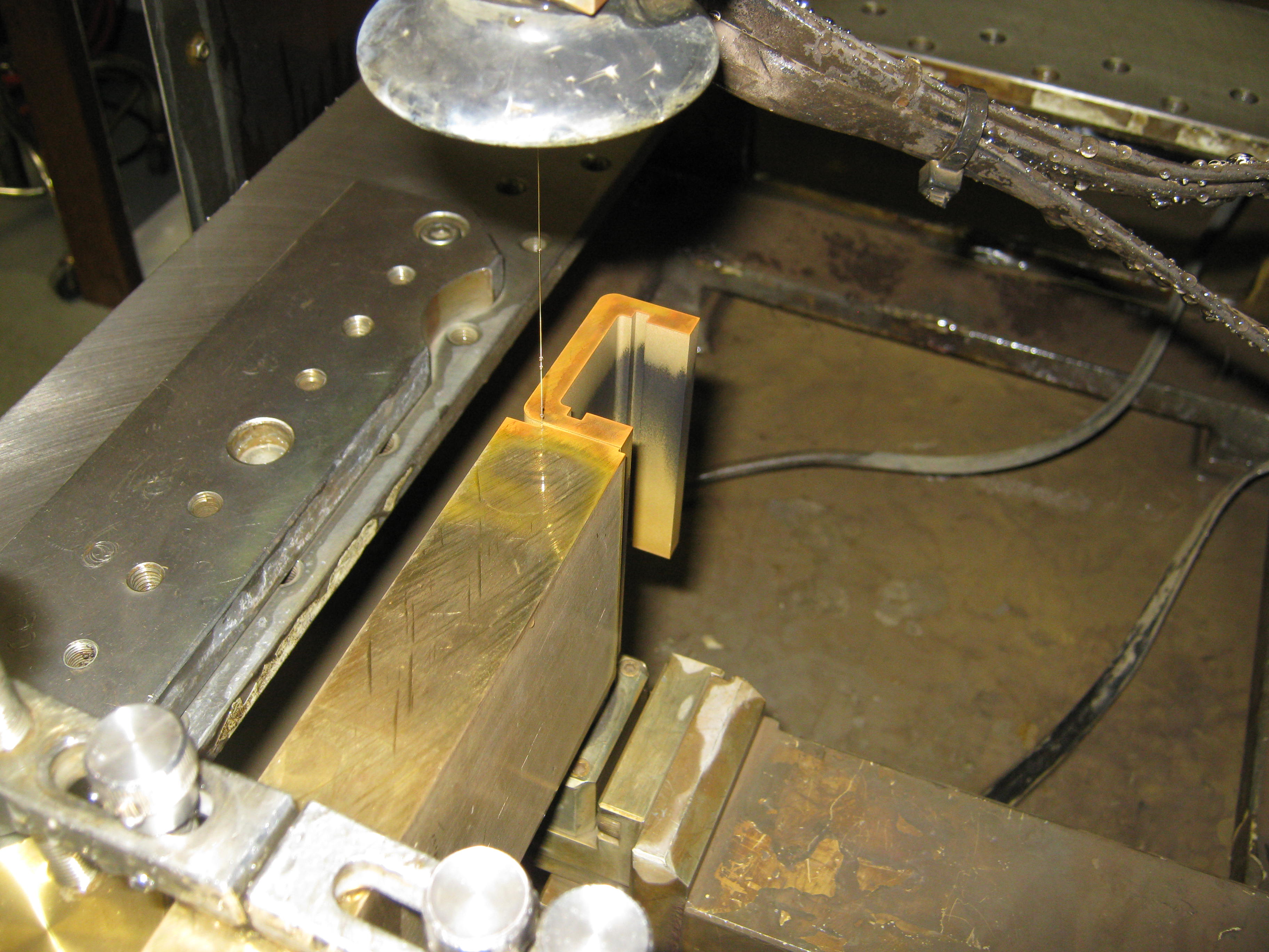
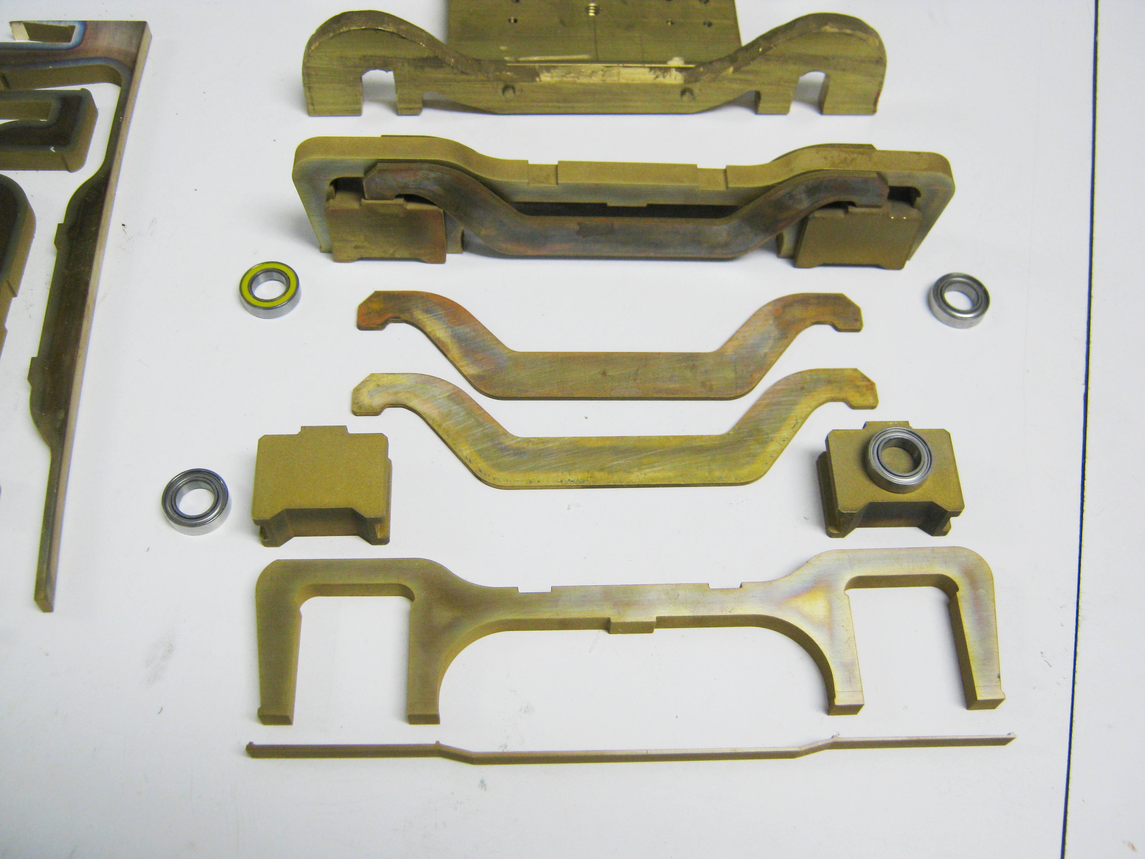
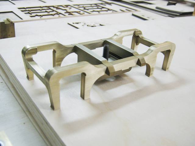
The first order of business on my portion of the L-105 project was to complete the Baldwin designed lead truck. This same lead truck was, like the trailing truck and tender, also used on the M-68 4-8-4, the two classes of locomotive being purpose built by Baldwin to have many interchangeable parts. Since I did not have part drawings of the L-105 lead truck--only the elevation and section drawings above--about 25 hours of CAD work were required to trace and guesstimate the truck's design. 115 man-hours of machining and assembly work later, the first truck was finished by me in mid-January of 2011. This is only the second 4-wheel lead truck that I have built, the first being a somewhat stiff affair I filed from brass bits and pieces about ten years ago for a model of Little River Lumber Co. baby 4-6-2 #110 (see thumbnail above). By contrast, the L-105 lead truck is sprung, equalized, and features a spring-loaded centering device. Heart-shaped rockers for the centering device were deemed too fiddly for a rugged outdoor, operating model.
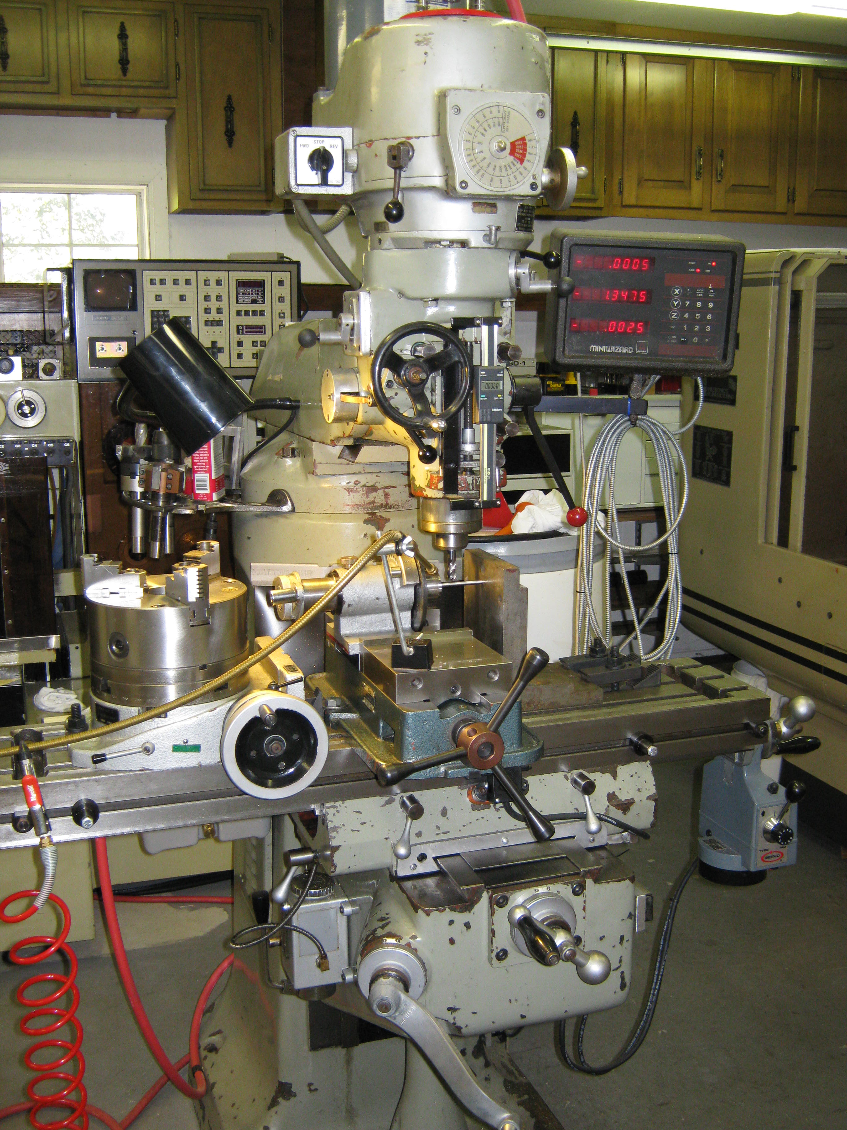
Most of the lead truck's brass parts were cut on my Japax wire EDM with a bit of additional mill work done on a Bridgeport clone. 36" lead truck wheels were supplied by Bill Brisko of Pacific Locomotive Works. Bushings and axles were made on my Monarch 10EE turret lathe. I'm confident that if I had it to do it over again, I would make the frame and centering components as casting patterns, and then have additional copies investment cast, which would greatly amortize the cost of so much machine work. Even so, I'm pleased with the results. My thanks go to Capt. Tom Mix (USMC, Retired) and master-modelmaker Kelley Morris for their suggestions, insight and superb examples from the smaller scales--and of course to Gary Bartlow for making this all possible. |
|
300.jpg) .JPG) L-105
Lead Engine Unit CAD Drawings
(updated 12-8-11) L-105
Lead Engine Unit CAD Drawings
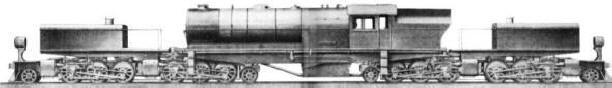
(updated 12-8-11)• The Prototype--The L-105 was an early recipient of integrally cast cylinders, frames and valve gear supports. These massive steel castings were a honeycomb of pockets, undercuts and cores, including fully enclosed voids which served as air tanks. Designed to maximize frame strength and overcome one of the chief maintenance headaches common to built up frames, integrally cast ones overcame the natural tendency of bolted together frames & cylinders to work themselves lose due to vibration. Out of tram frames meant binds, hot bearings, worn bearing surfaces & misaligned cylinders. Baldwin subsidiary General Steel Castings provided these huge sand castings, pouring them in sand filled pits on the foundry floor. As an aside, the Pennsy's S1 6-4-4-6 duplex of 1939 World's Fair fame holds the record as the single largest one-piece locomotive frame ever cast. Sadly, General Steel Castings is no more and no foundry in America any longer has the capacity to do such large, open pours.
|
|
.jpg) 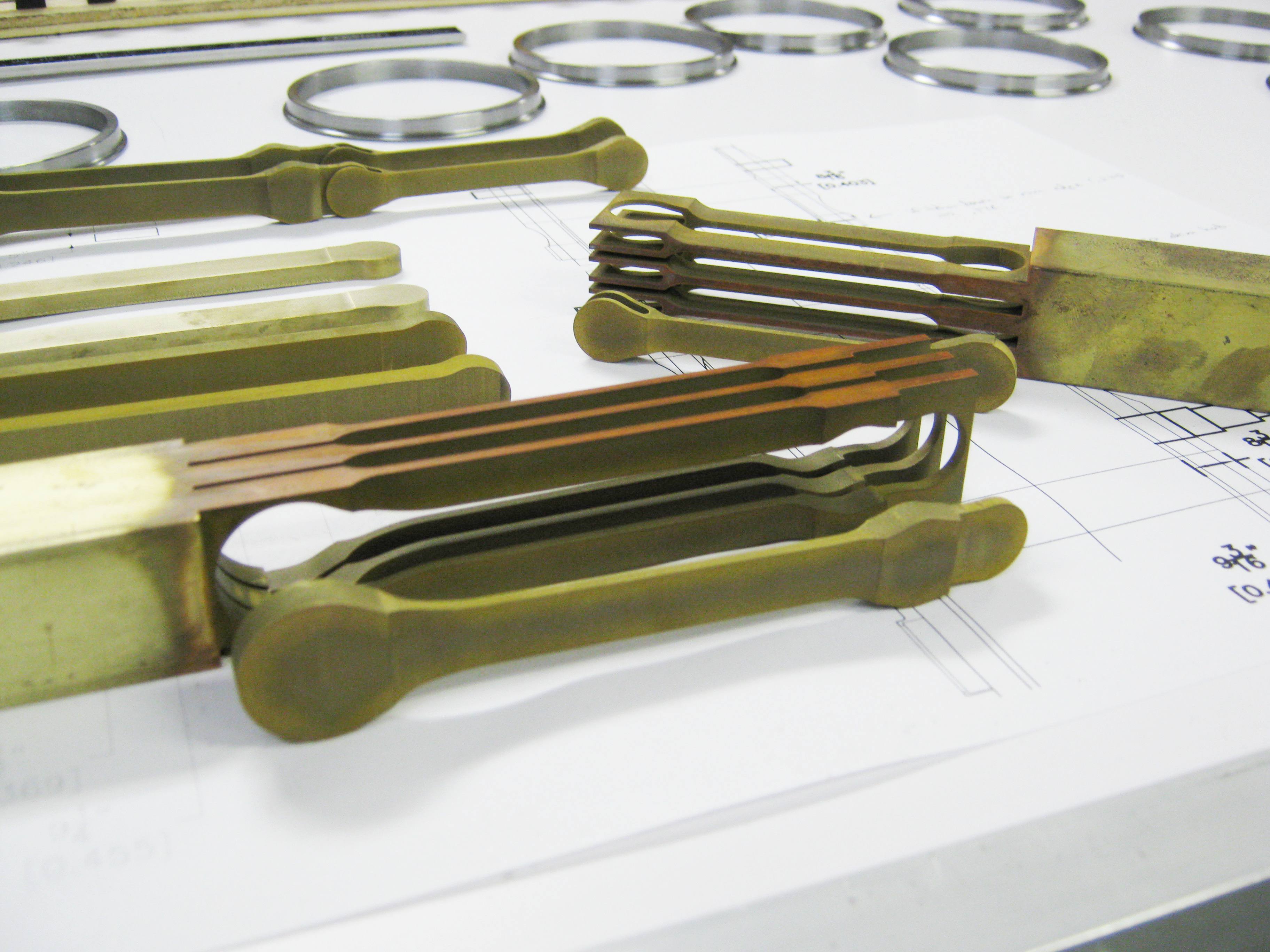 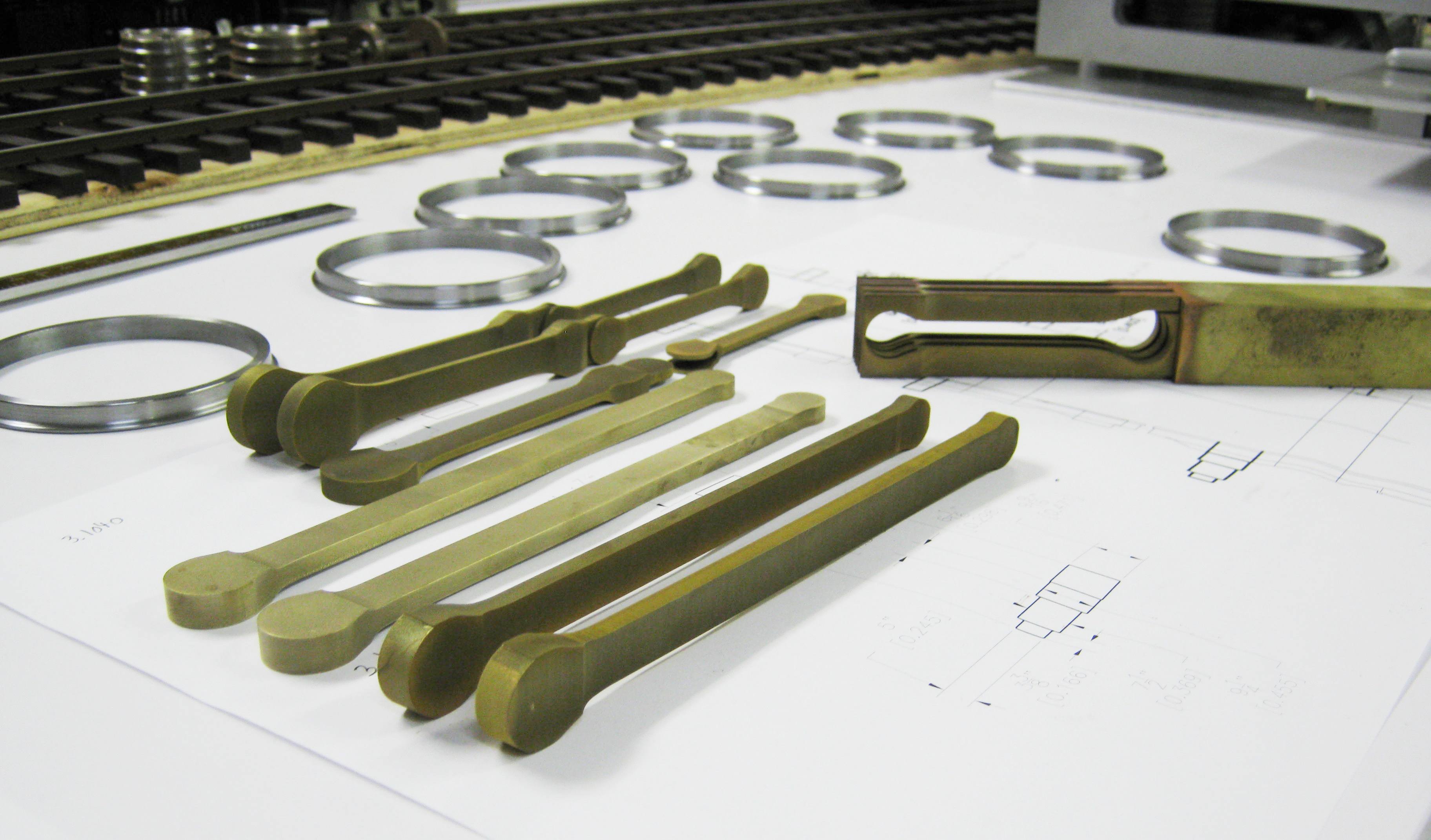 .JPG) L-105
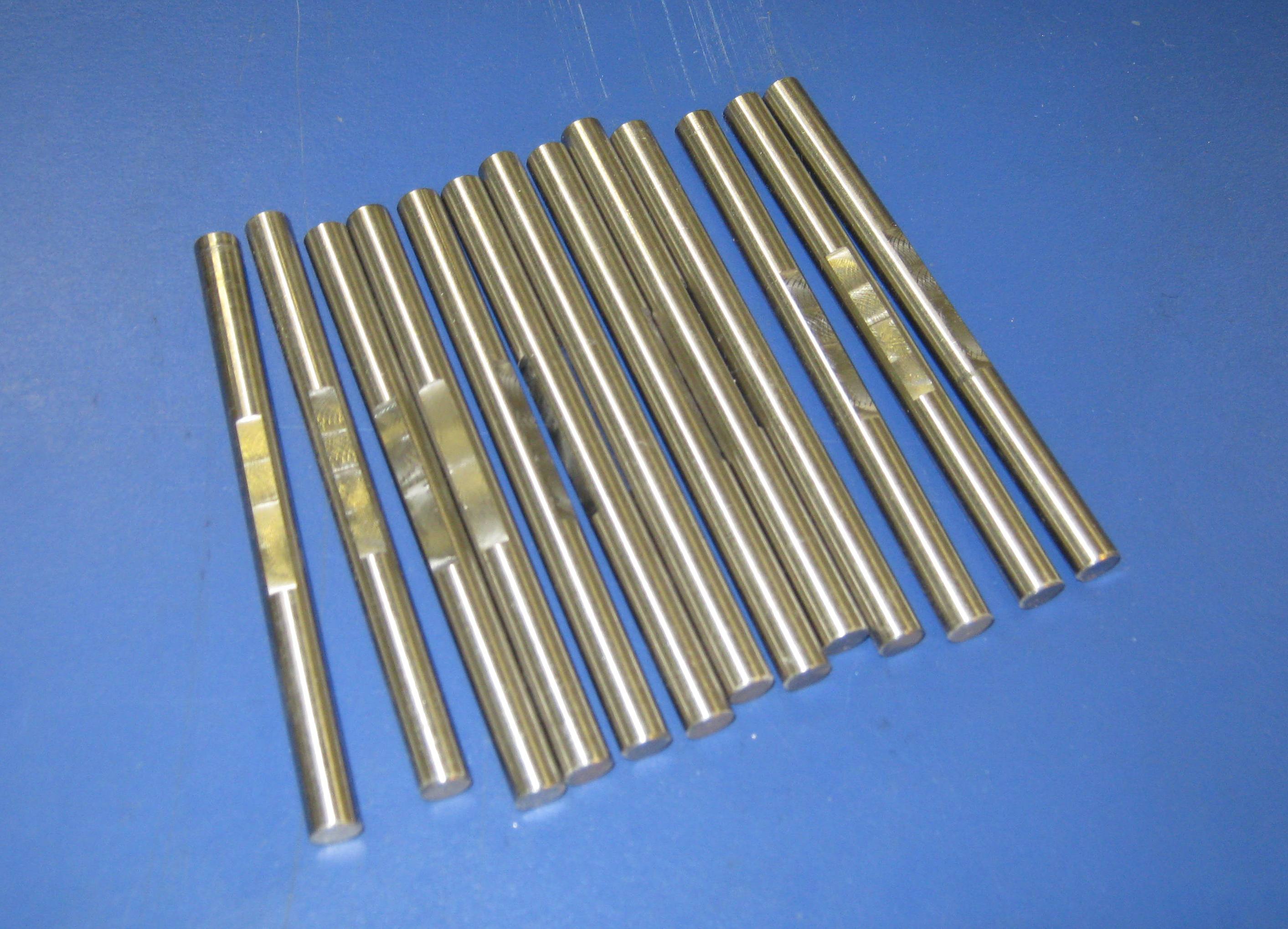
Side & Main Rods
(updated 11-28-11) L-105
Side & Main Rods
(updated 11-28-11)My Japax wire EDM was kept hot during October of 2011 producing the four main rods, front side rods, and four back side rods for the L-105. These were first drawn in AutoCAD by tracing the original D&RGW blueprint provided by the Colorado Railroad Museum and then cut on two sides from 1" square brass bar. These were not casting patterns but the actual production rods. One of the lessons learned here is that it is more economical to make a casting pattern for each rod on the wire EDM rather than to burn every one individually since only about 4ľ hours of programming time was required for the three different rods but 36Ľ hours were necessary for cutting all 12 production rods. Nevertheless, I am pleased with the results, and here are a few thumbnail pics of the results. Some milling remains, namely for the fluting on the main rods, and the fitting of bearings. |
|
|
|
|
| (to be continued . . .) | |
| Next Stop: Even Bigger Steam: The UP Challenger & Big Boy | |
|
Last update: 8 December 2011
|
| Copyright 2004-2009 CumberlandModelEngineering.com. All Rights Reserved |
.jpg) D&RGW
L-105 4-6-6-4
D&RGW
L-105 4-6-6-4.jpg)
.jpg)
.jpg)
.JPG)
.JPG)
.JPG)
.JPG)
.jpg)
.jpg)
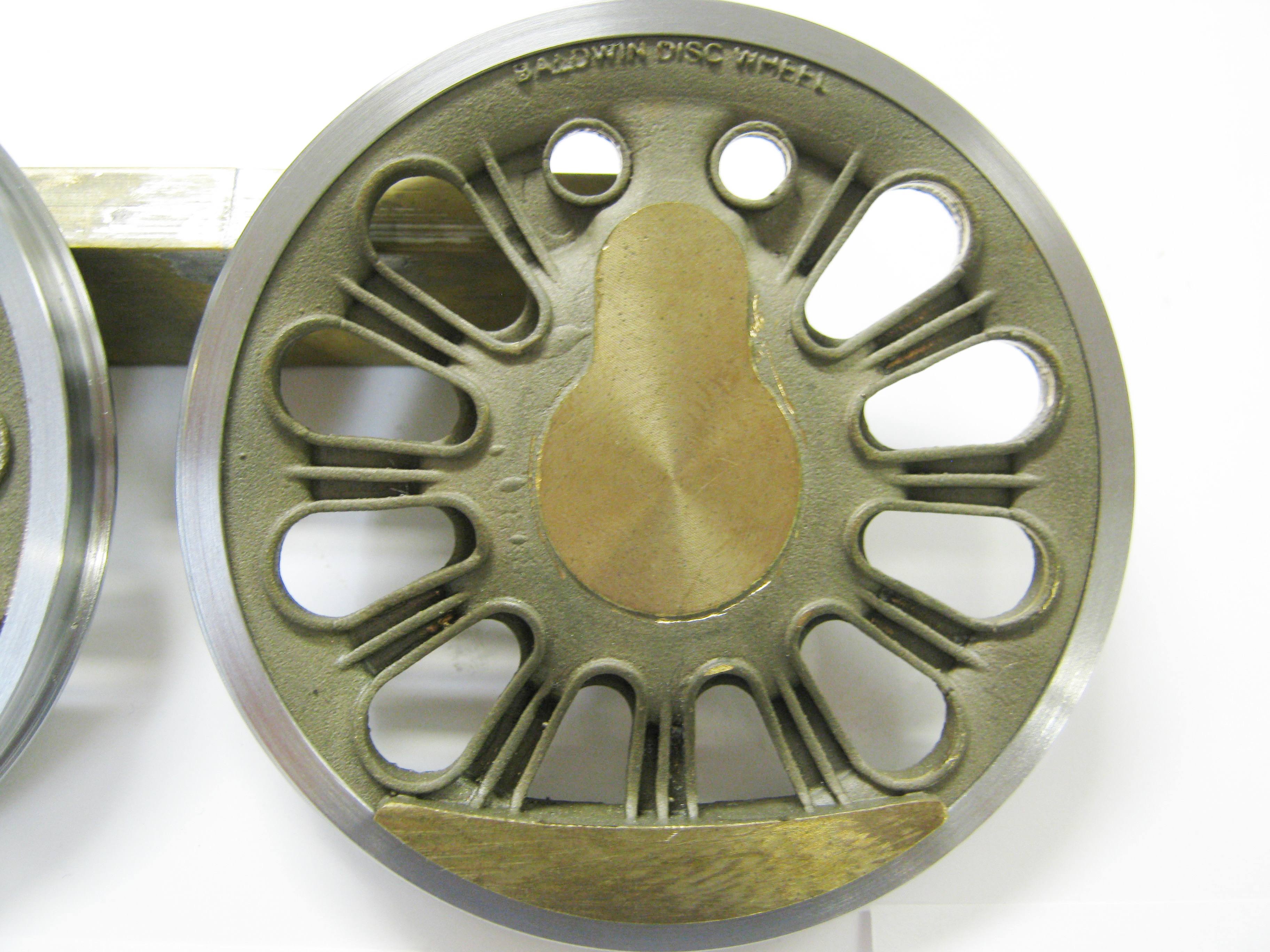
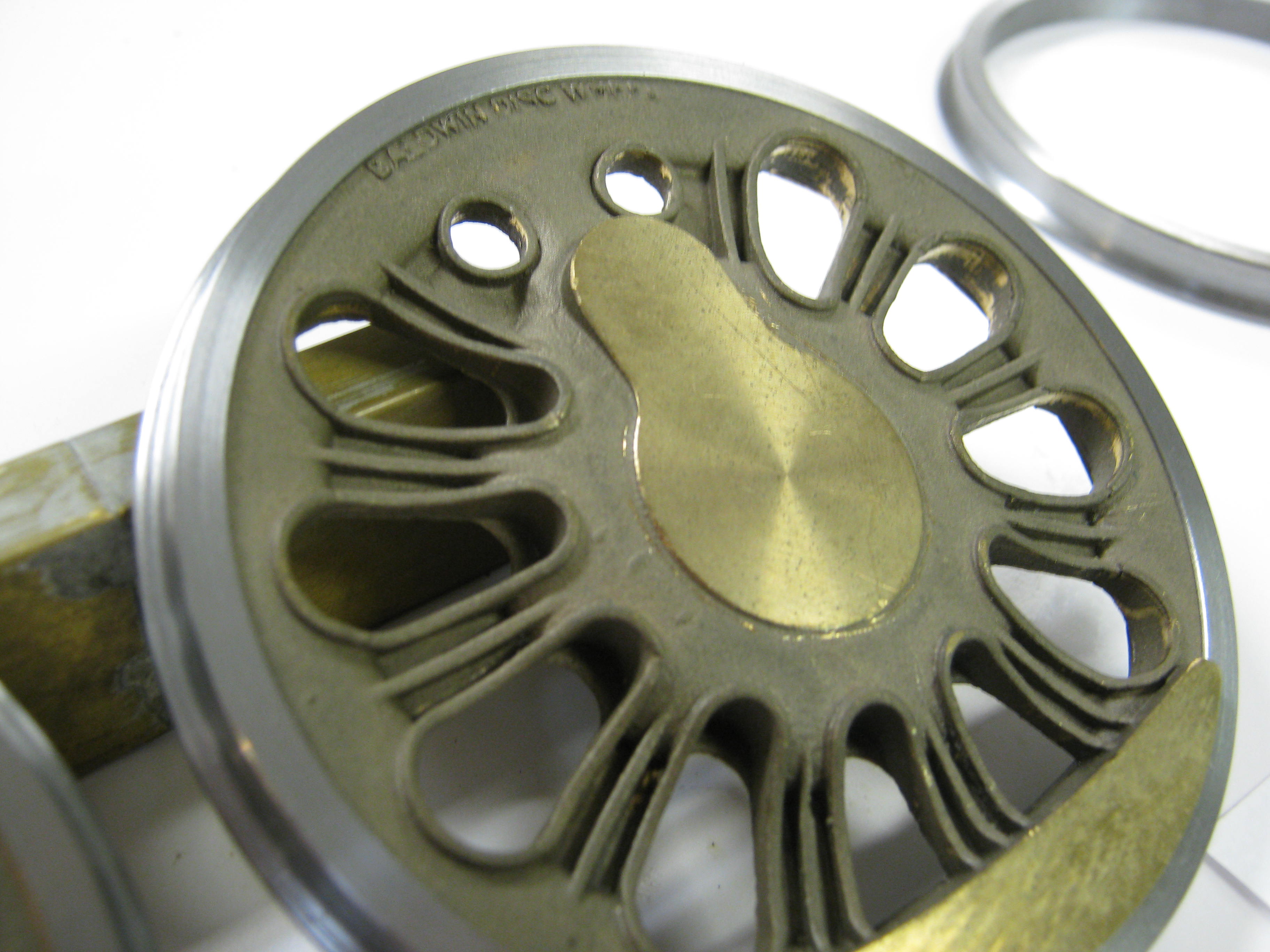
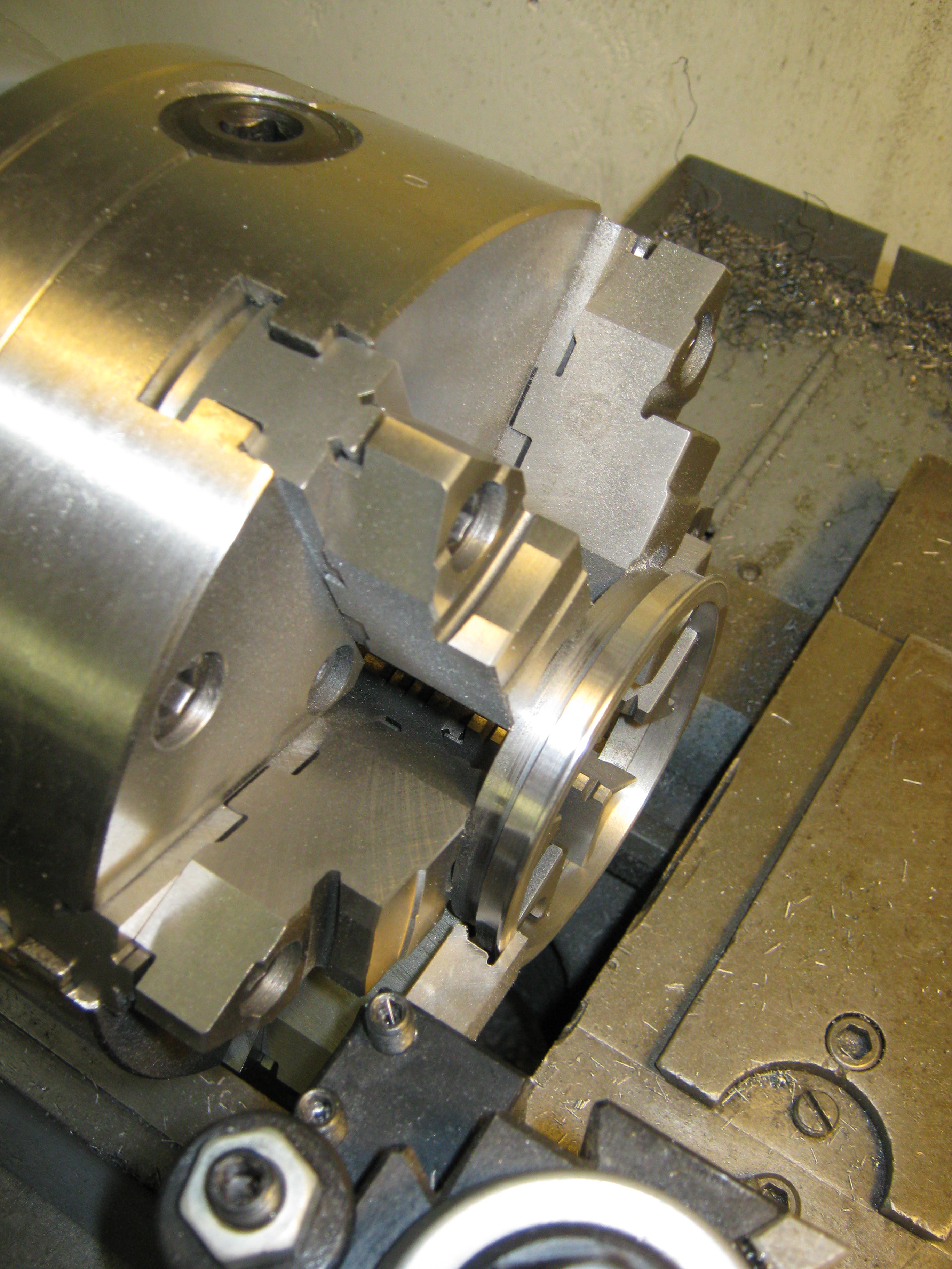
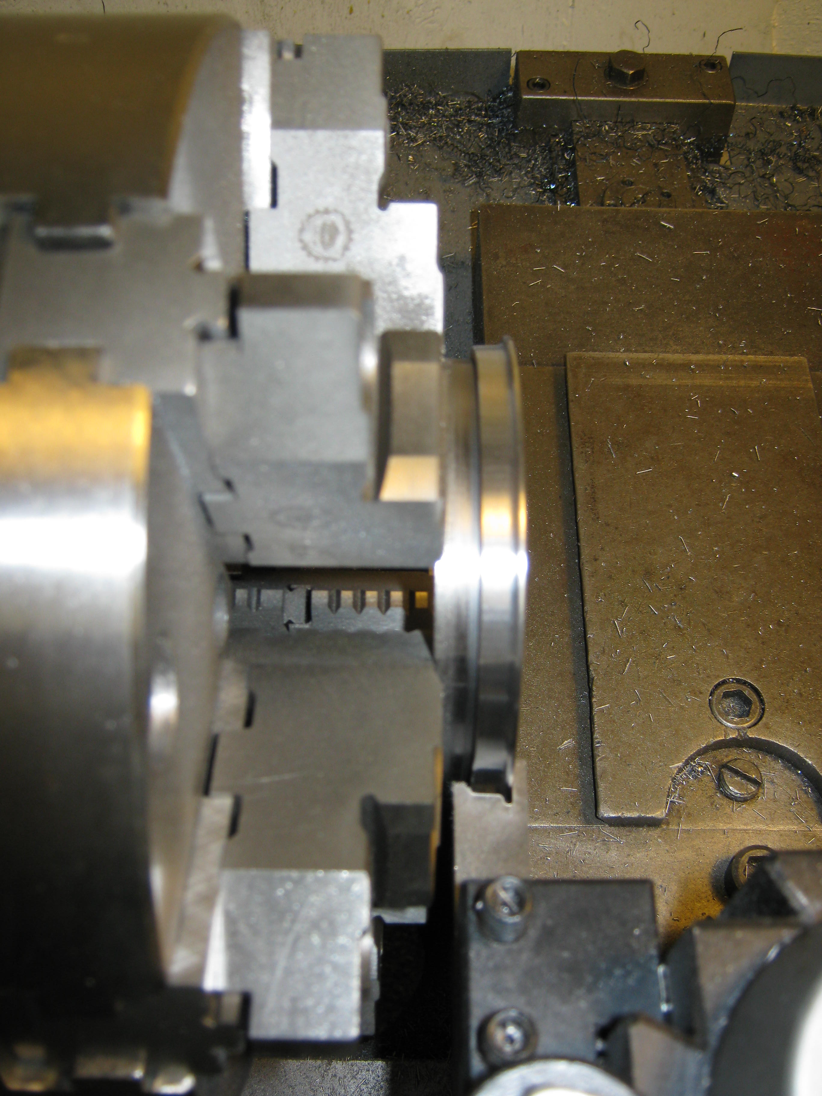
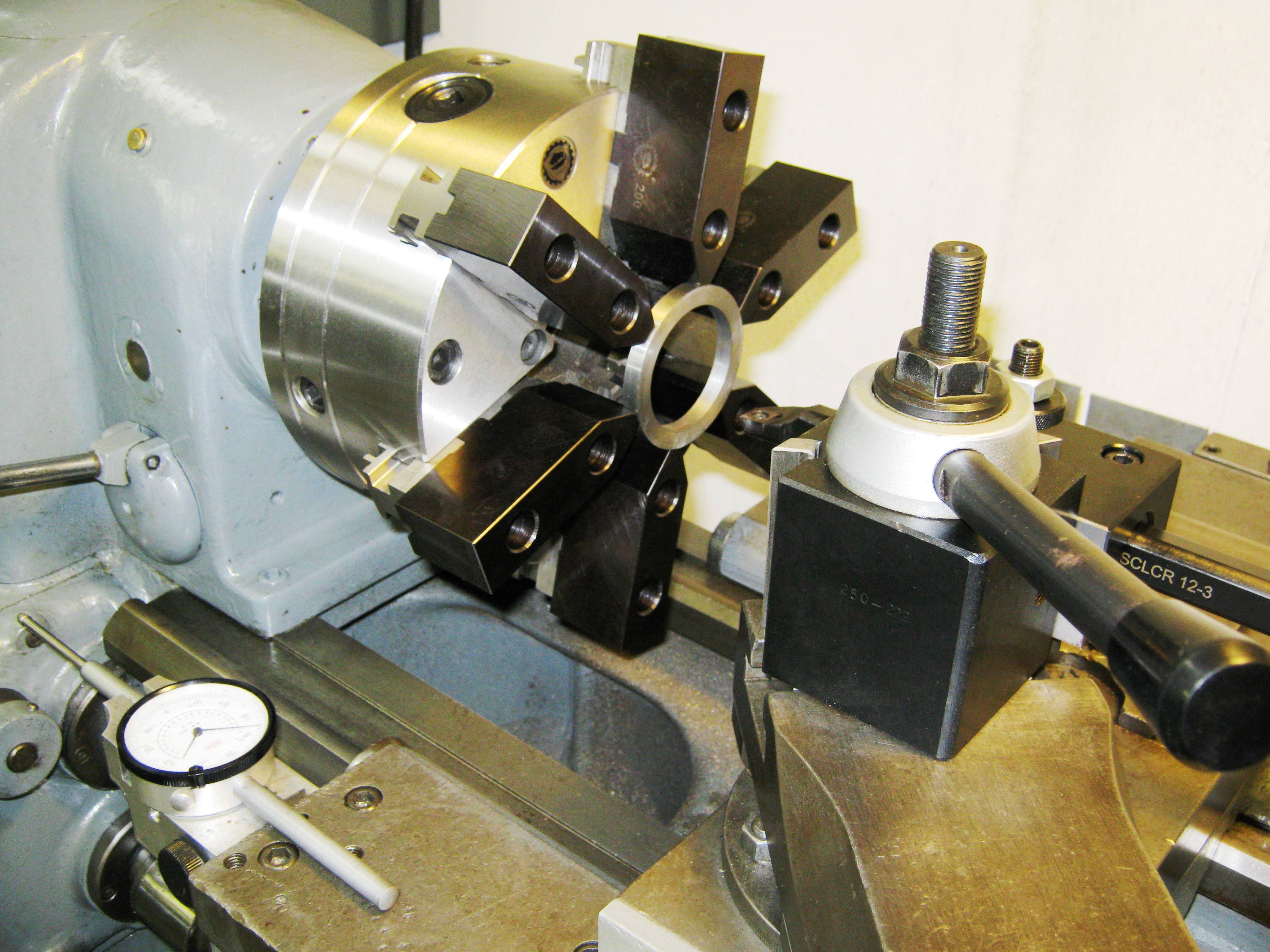
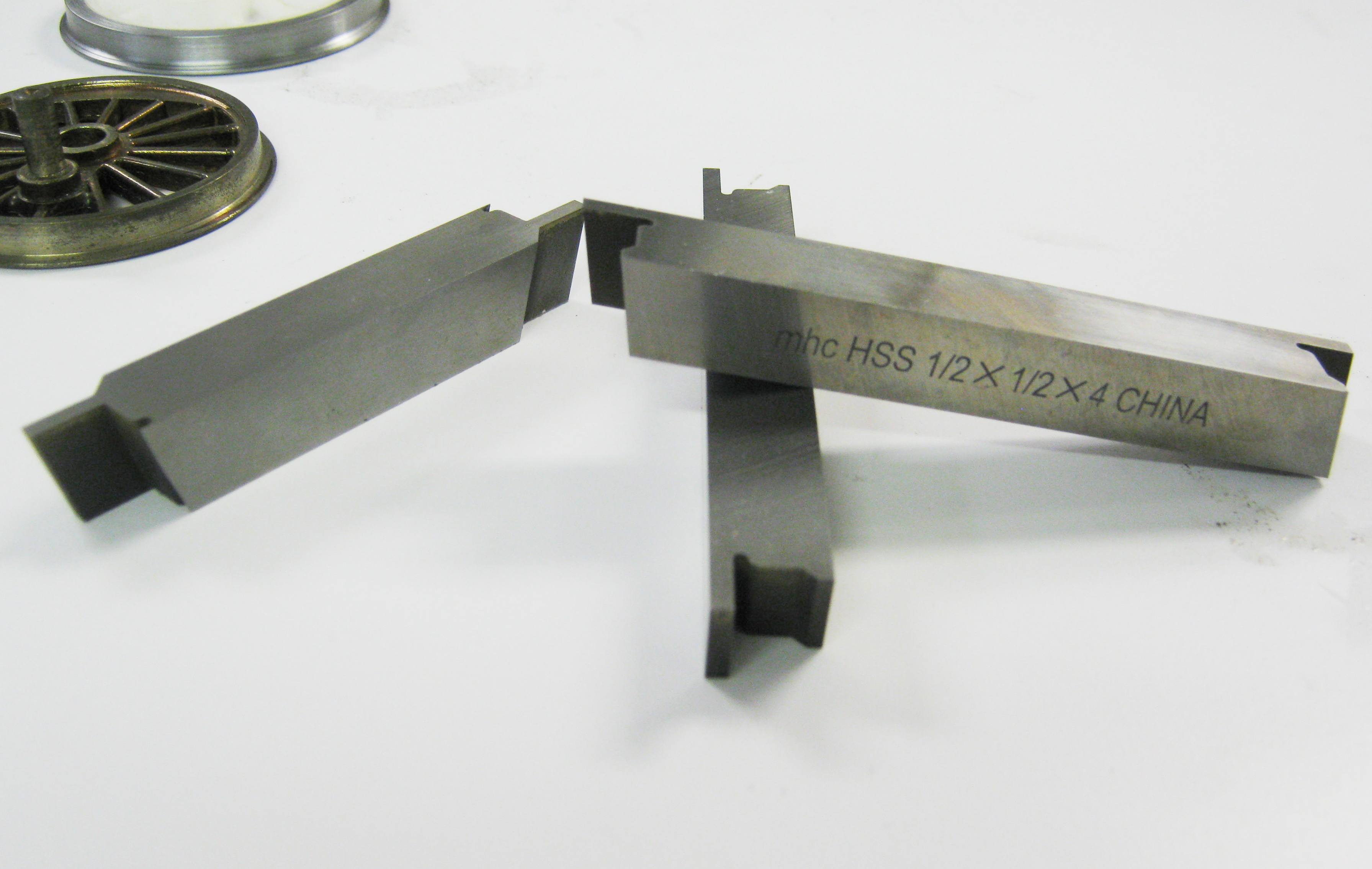
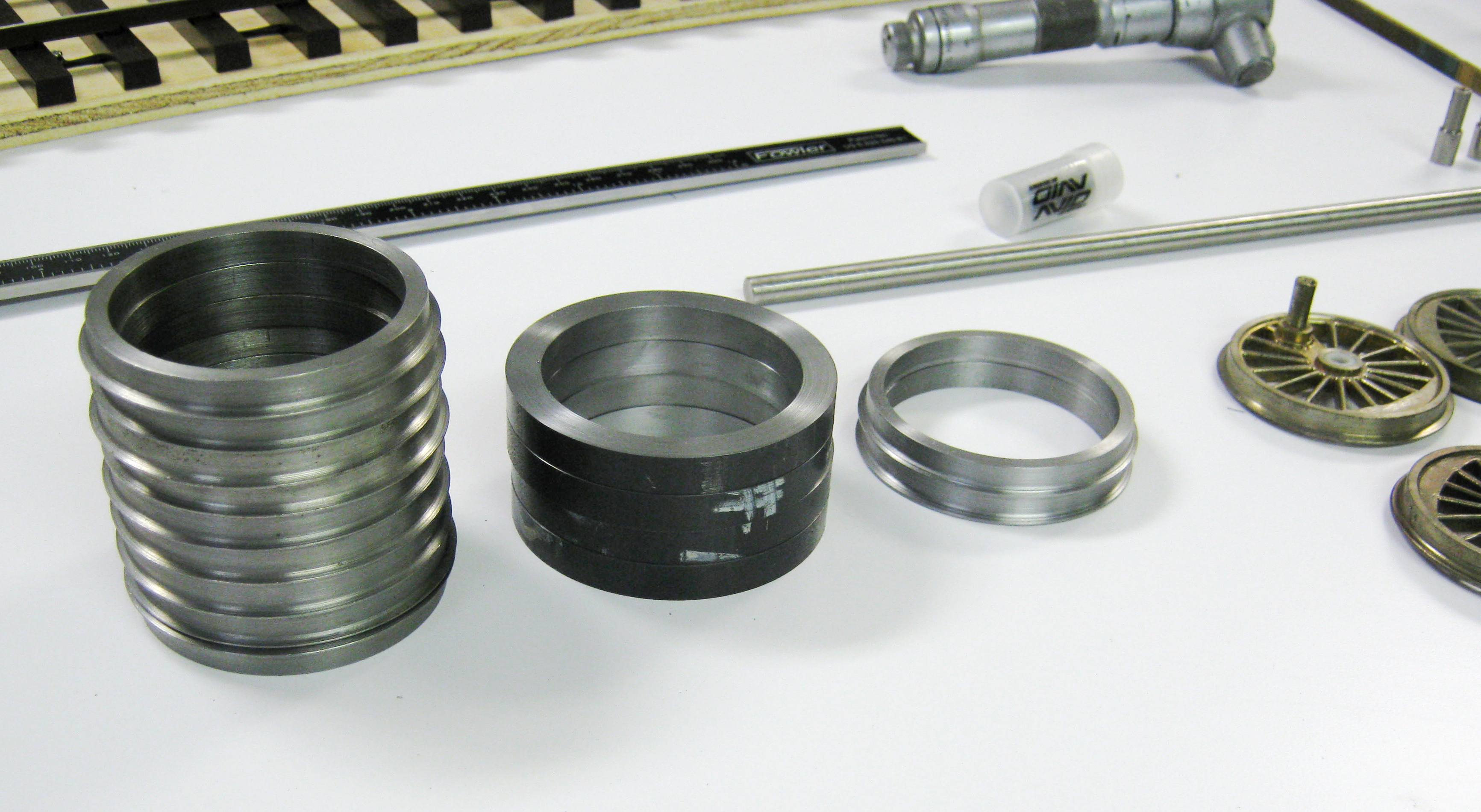
.jpg) 70"
Baldwin Disc Drivers & Axles
(updated 11-28-11)
70"
Baldwin Disc Drivers & Axles
(updated 11-28-11)%20003.jpg)
%20007.jpg)
%20002.jpg)
%20006.jpg)
%20003.jpg)
%20013.jpg)
.JPG)