.JPG)  |
|
"Your source for standard gauge modeling in 1:20.3" |
|
|
|
|
|
|
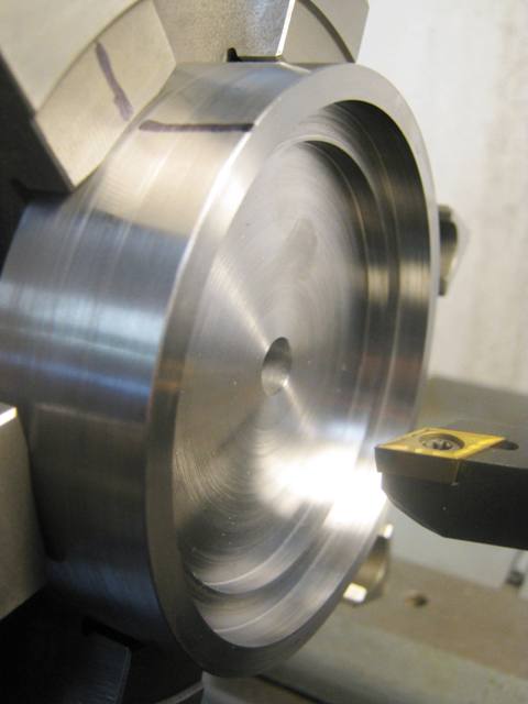
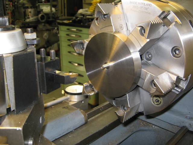
Machining Drivers
(from 7-8-12)
|
(How To Machine a Cast Driver Center, Part I--July 2012) |
.jpg) 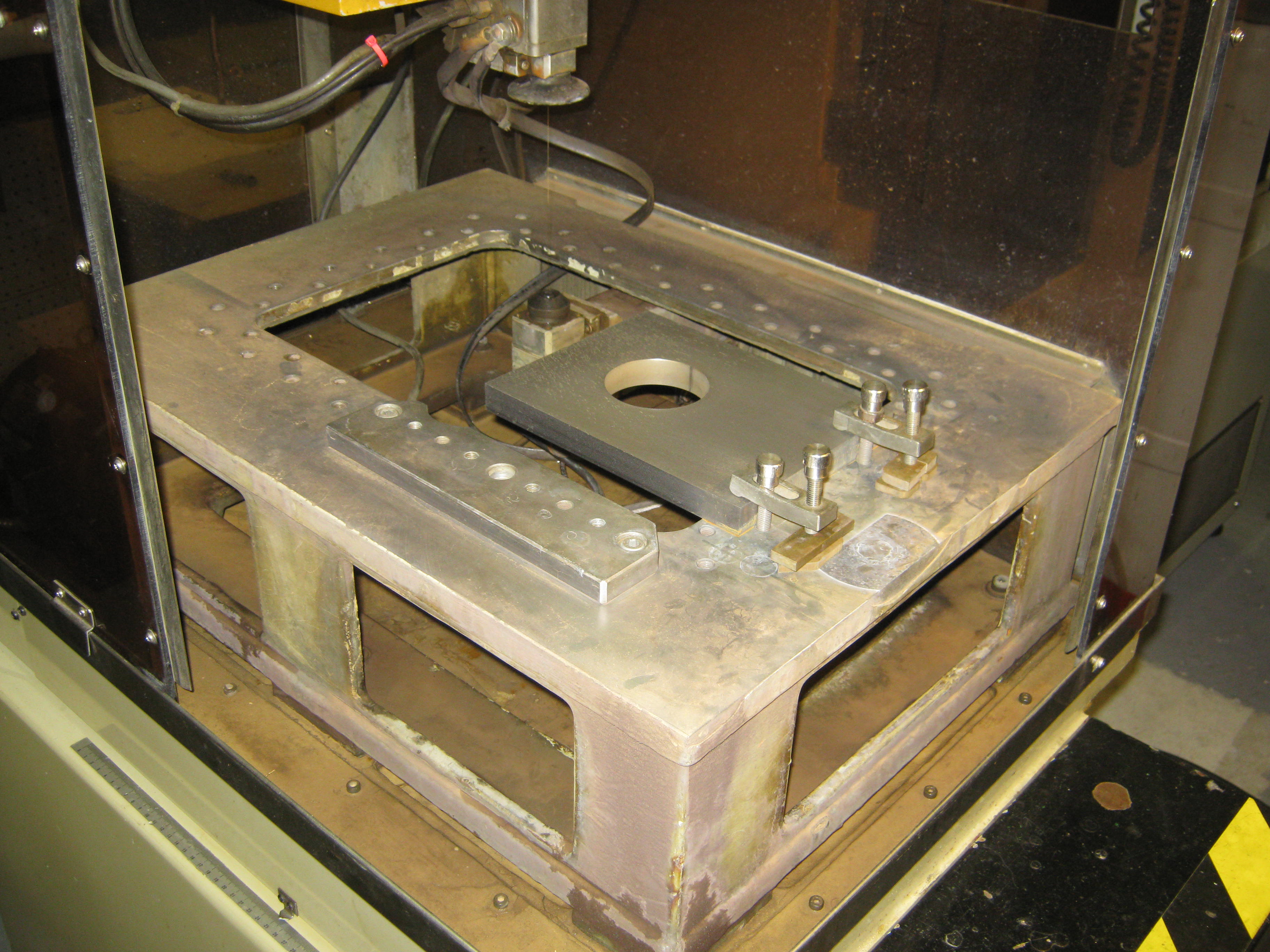 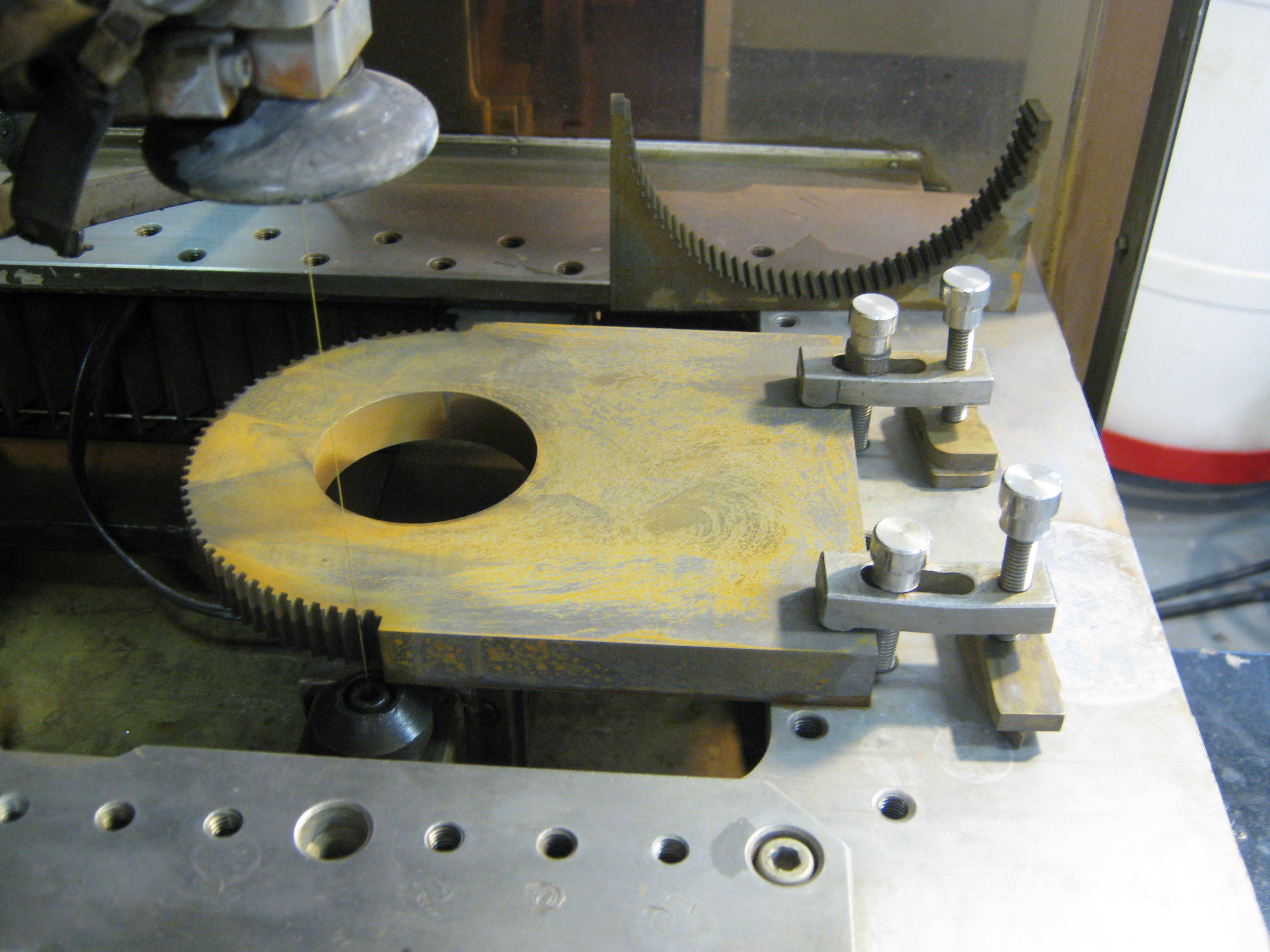 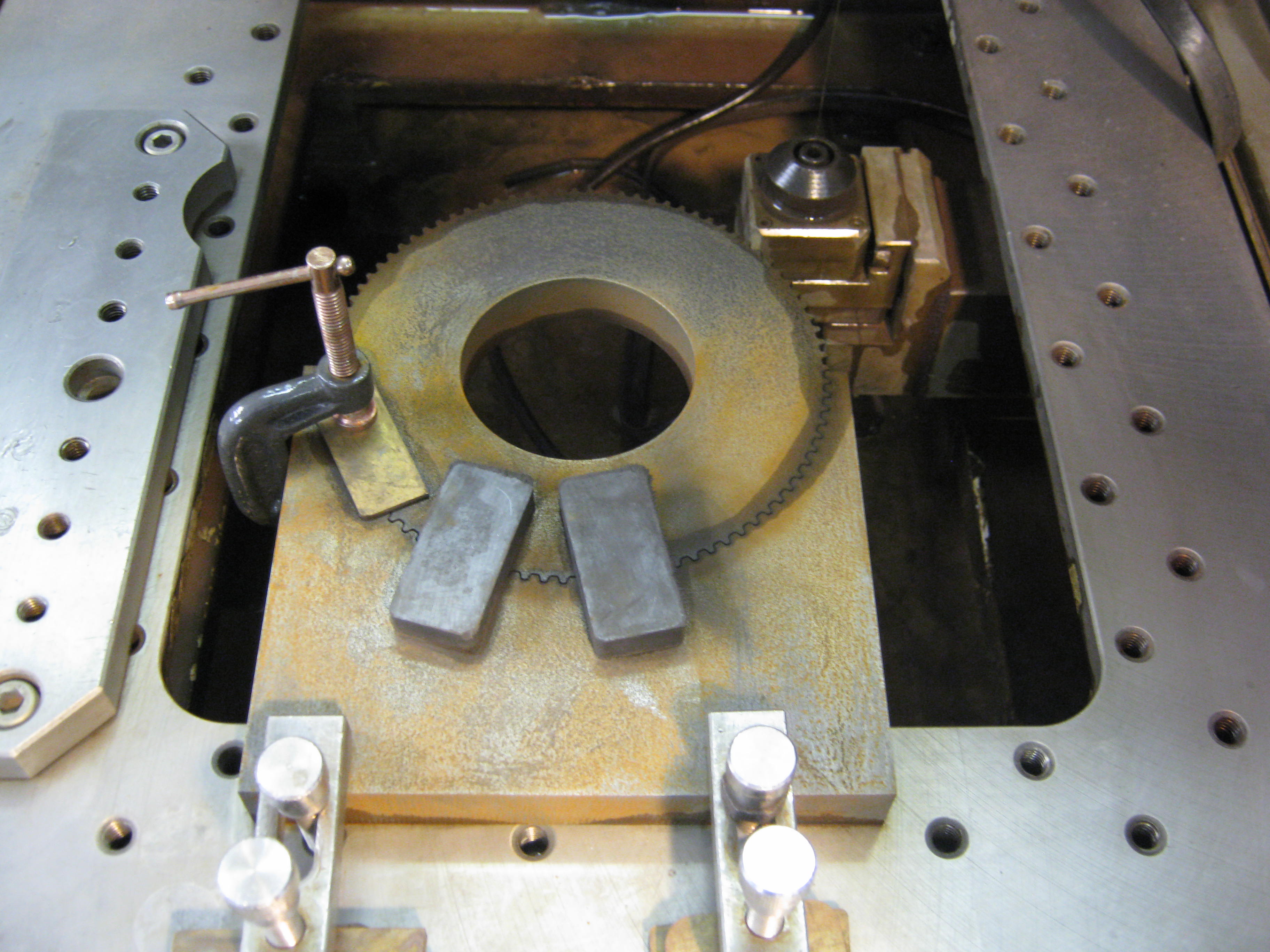 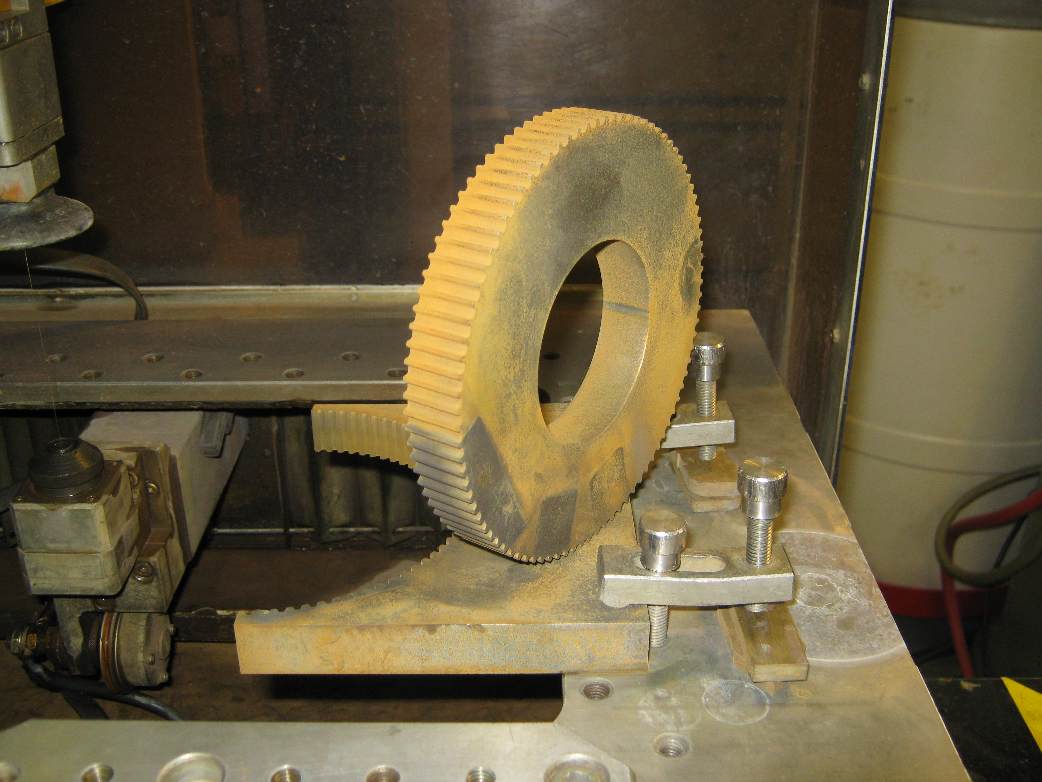 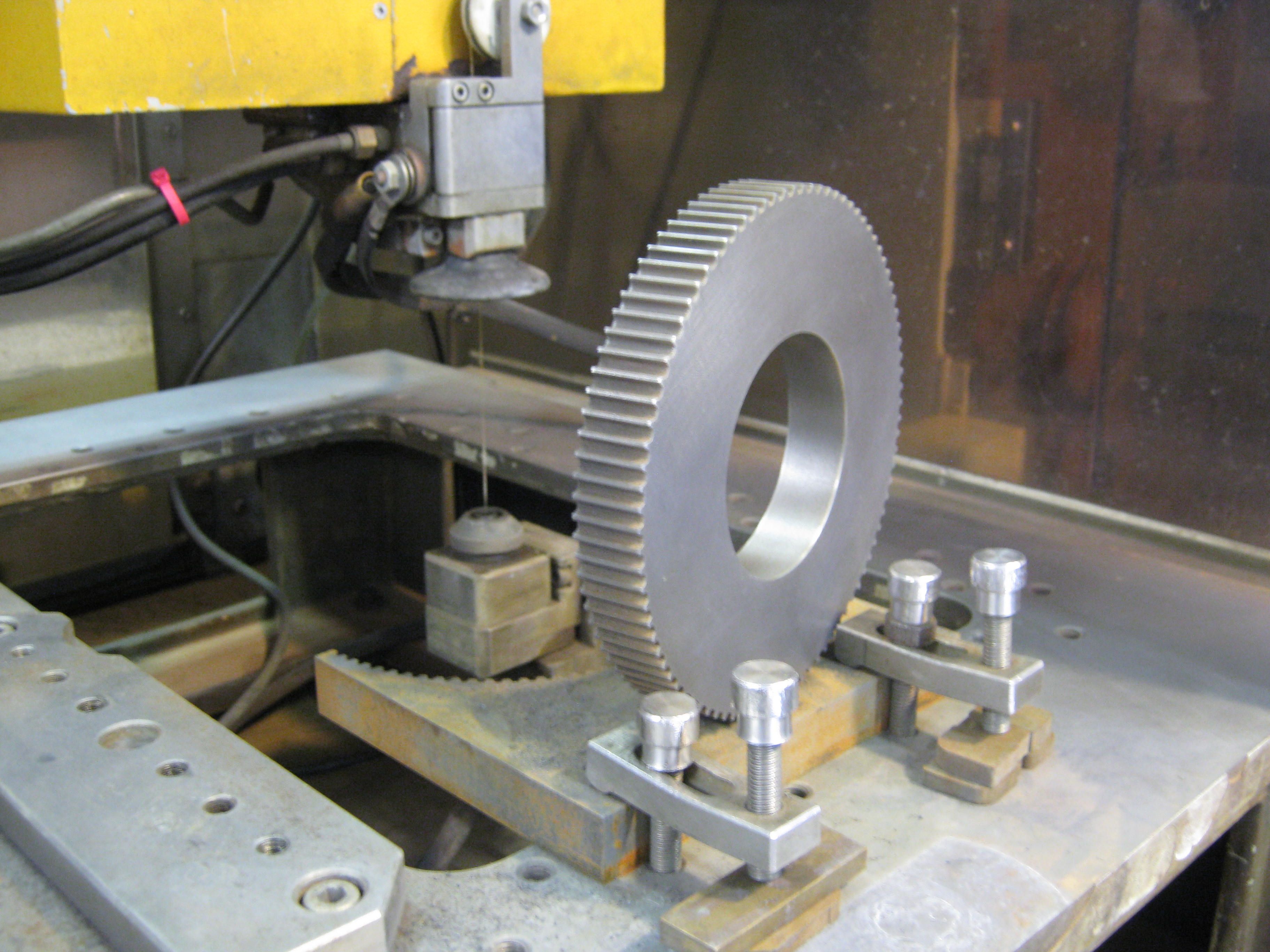 Get
It In Gear
(updated 6-13-12) Get
It In Gear
(updated 6-13-12)My friend and fellow home shop machinist Randy Gordon-Gilmore asked me to help him with a CNC project which involves taking a small manual lathe and retro-fitting it with x and z axis servo motors so that it can be run as a CNC 4th axis on his Tormach "personal CNC" mill. Randy, as readers of this site may recall, is the talented individual behind the first fully CNC machined driver center patterns in F scale, milled in 3D from brass plate for my Southern Railway Ps-4 Pacific locomotive. Randy is no slouch, but he needed a big spur gear for a toothed belt which was not commercially available in the right OD and diametrical pitch: voila . . . wire EDM to the rescue. Wire EDM is often used for custom-making one-off gears when access to gear hobs is either too expensive or not possible. So with a little help from BobCad-CAM and my Japax, a 1" thick slab of cold-rolled was transformed into this. I also learned something about mid-1980s NC technology: Memory was then very expensive and at a premium. The NC controller on the Japax LU3B could only store about 120 lines of G code in its RAM; and so an old stand-by had to be used: the magnetic tape reader. This was a first for me. I has a number of blank data cassettes left over from the Japax's days at Pellissippi State Technical Community College. After a bit of tutoring from the folks at McWilliams Machinery, who still service and sell refurbished Japax EDMs, we were off and running. Each subprogram cut about 1/4 of the circumference of the gear (now that's a lot of I and J moves for each tooth in the gear). Magnets held the gear in place while the final cuts were made. With a bit of surface rust cleanup, it's done! |
|
.jpg) SRHA
Convention
(updated 5-22-12) SRHA
Convention
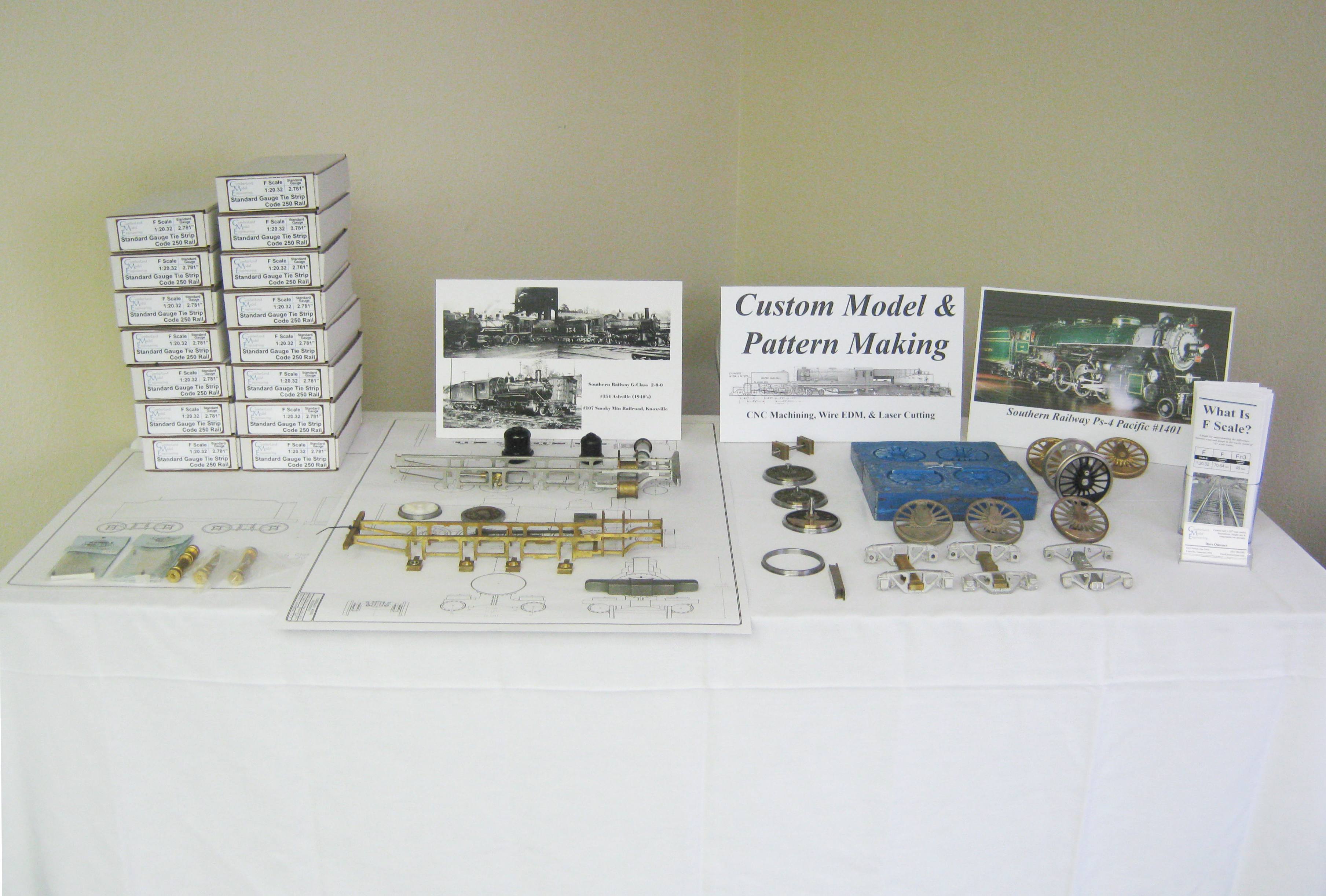
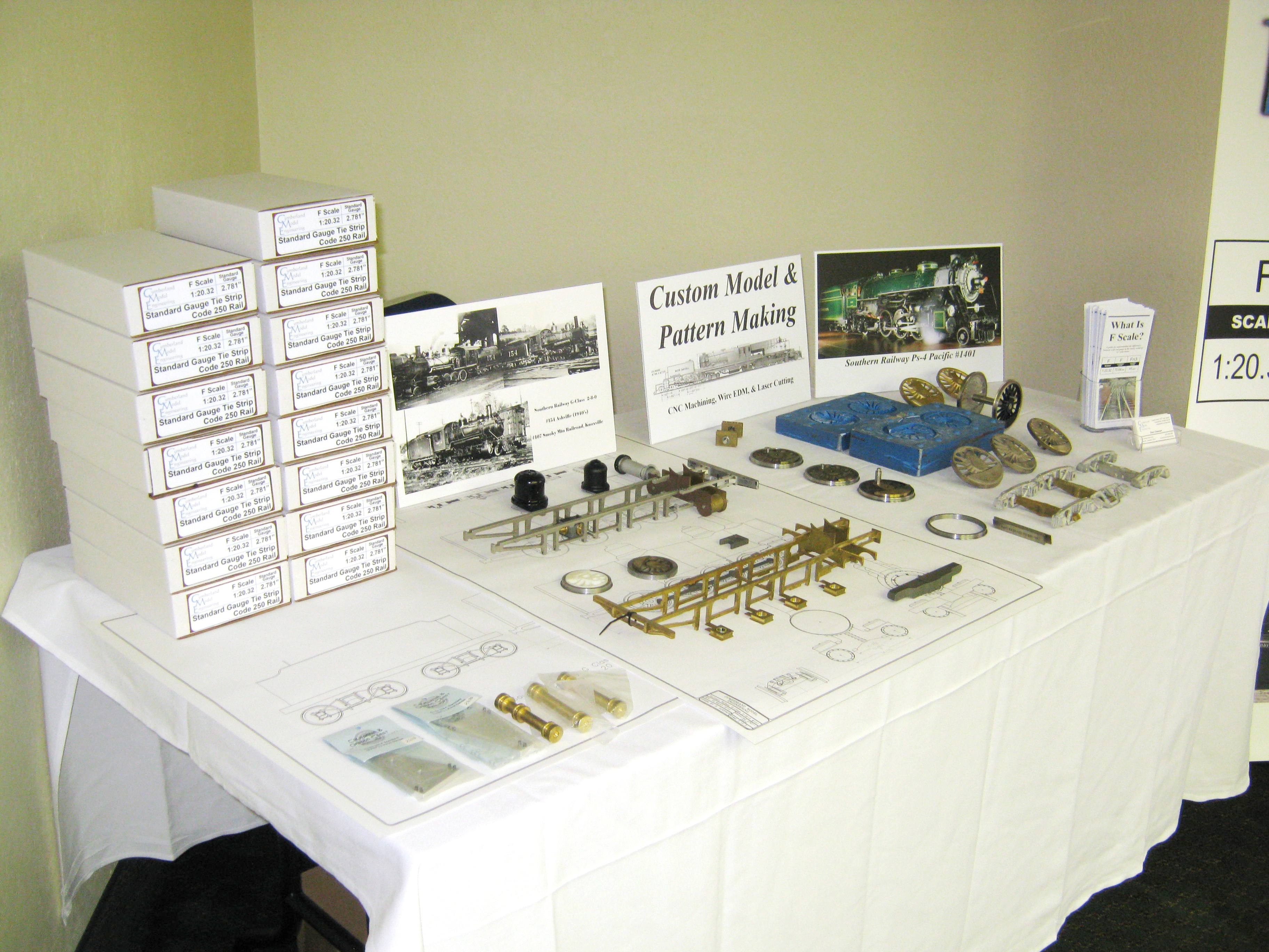
(updated 5-22-12)The Southern Railway came back to life for a few short days this past weekend, May 18-20, thanks to the generosity of corporate successor Norfolk Southern, its president and CEO, Mr. Wick Moorman, the Tennessee Valley Railroad Museum, and the Southern Railway Historical Association. A delightful ride around Chattanooga on Saturday behind SR GP-38-2 #2594 over the trackage of NS, TVRM, the Chattanooga Belt Line, and the Chattanooga & Chickamauga Railroad was accompanied by clinics, slide shows, a visit to TVRM's Soule Shops, a banquet with President Moorman as keynote speaker, and a handful of displays. Home base for the convention was the Chattanooga Choo Choo resort (the old Southern Railway Terminal refurbished in the 1970s to become a hotel and tourist destination). Two rooms set aside by the hotel were used as mini-exhibit halls for the SRHA. I was privileged to display my recent and ongoing projects, including the second test build of my Southern Railway 36' boxcar kit, components for SR G-class 2-8-0s #107 and #154, and driver patterns, as well as rubber mold and castings, for the SR Ps-4 pacific in F scale.
|
|
.JPG) Cumberland
Model Engineering Acquires Iron Creek Shops Track
Products
(updated 5-22-12) Cumberland
Model Engineering Acquires Iron Creek Shops Track
Products
(updated 5-22-12)I am pleased to announce that as of May of 2012, Cumberland Model Engineering has acquired the line of F scale track products formerly marketed by my friend Don Niday under the name of Iron Creek Products. These include both the dual gauge and standard gauge plastic tie strips for Llagas Creek code 250 & 215 rail, three-point track gages, and brass roller gages (for both code 250 and 332 rail). As of this writing another production run of dual gauge tie strip is planned for June and another set of plates for the injection mold which produces the plastic tie strip is planned, in this case to allow for customers to use either Micro Engineering code 332 aluminum rail or either LGB or Aristo-Craft code 332 brass rail. Tie strip will also now be offered assembled with rail in place. Overall I am very pleased by the transaction since in 2002/2003 I originally produced the 2D CAD drawings which became the basis for Don's tie strip. Don continues to be very active in the hobby, has made a great deal of progress on his indoor home F & Fn3 layout, and will still be marketing a number of cast resin detail parts as well as offering custom painting and weathering of both locomotives and rolling stock. New pricing and additional details will become available on the Track Products Page of my website. |
|
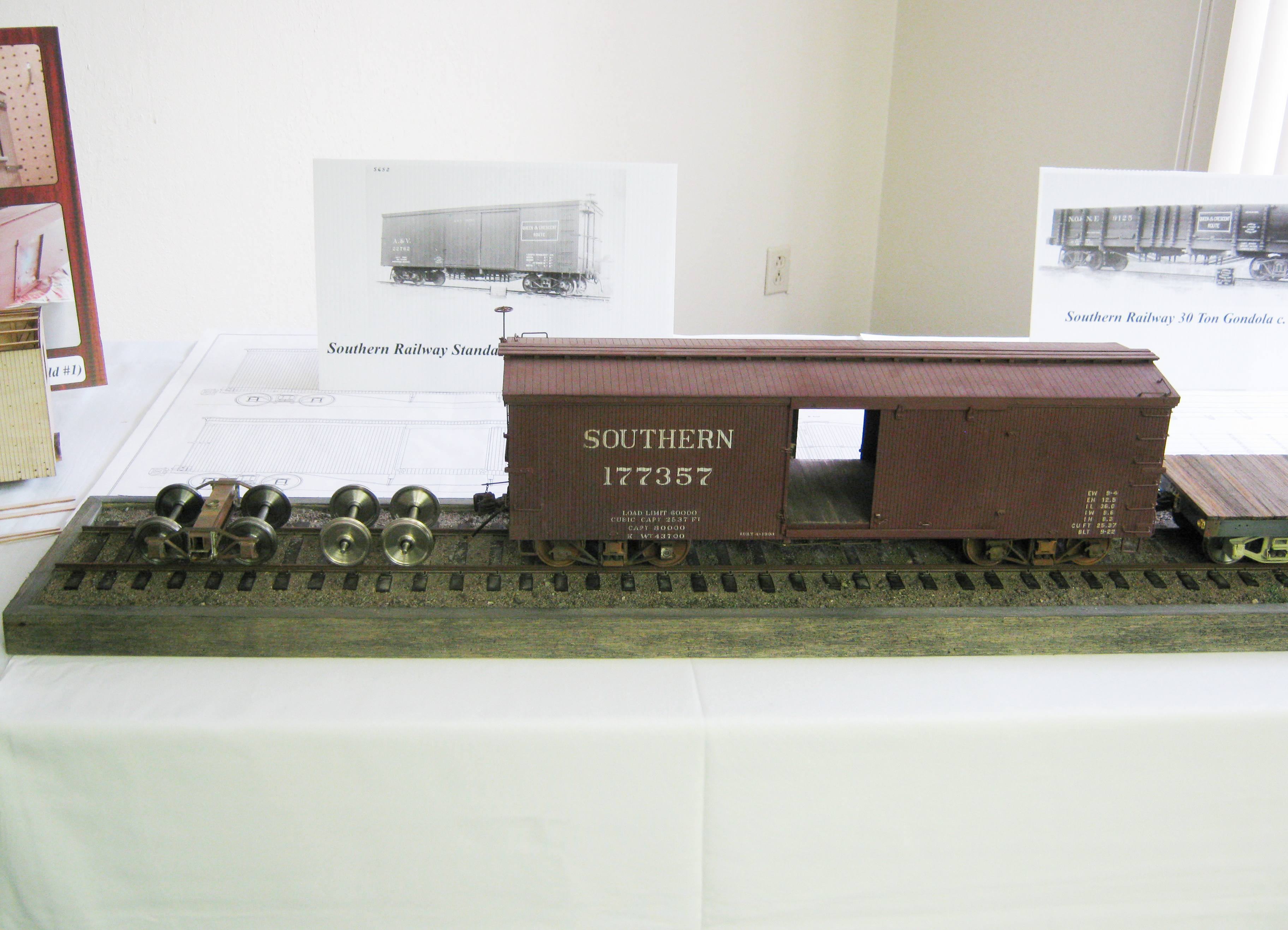
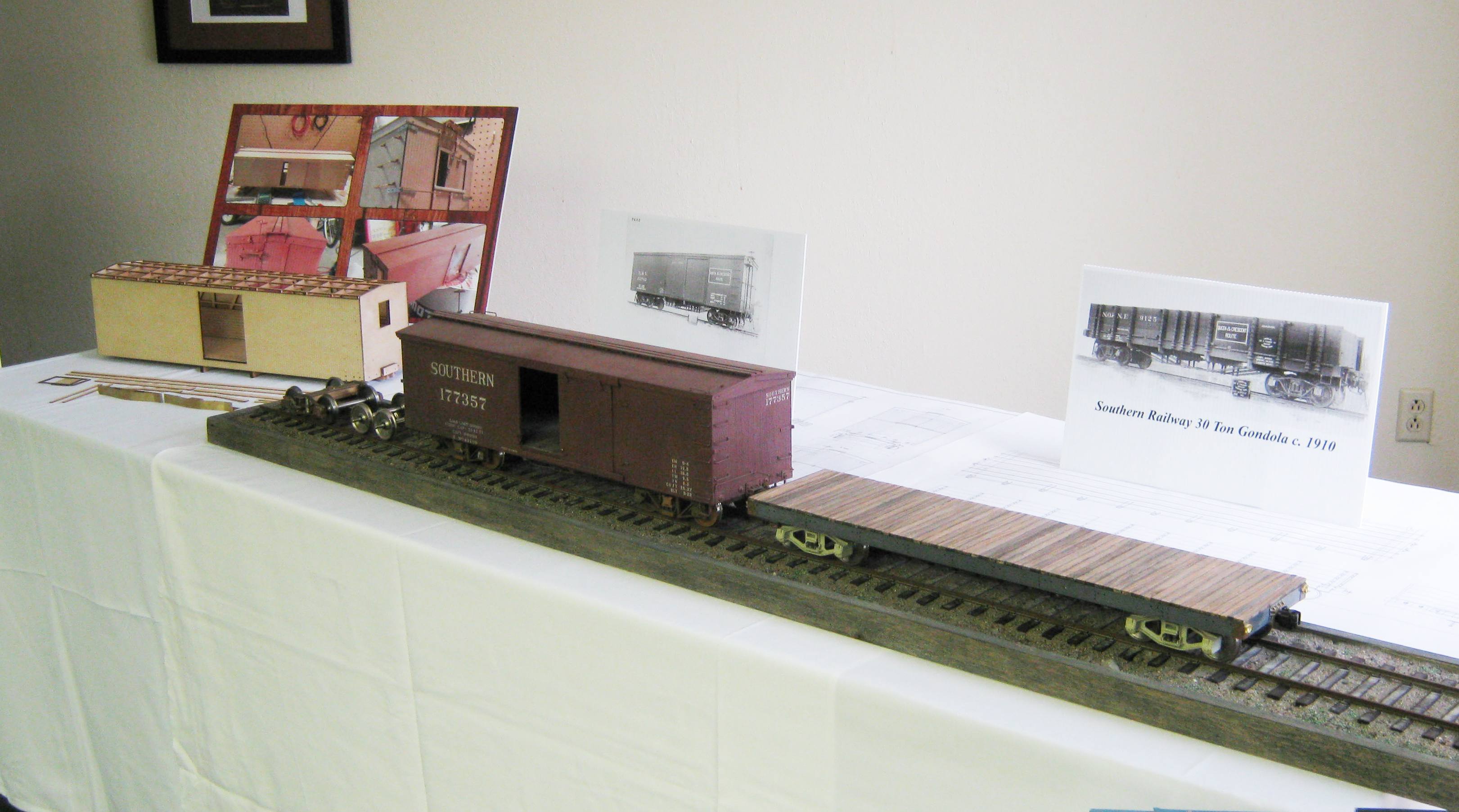
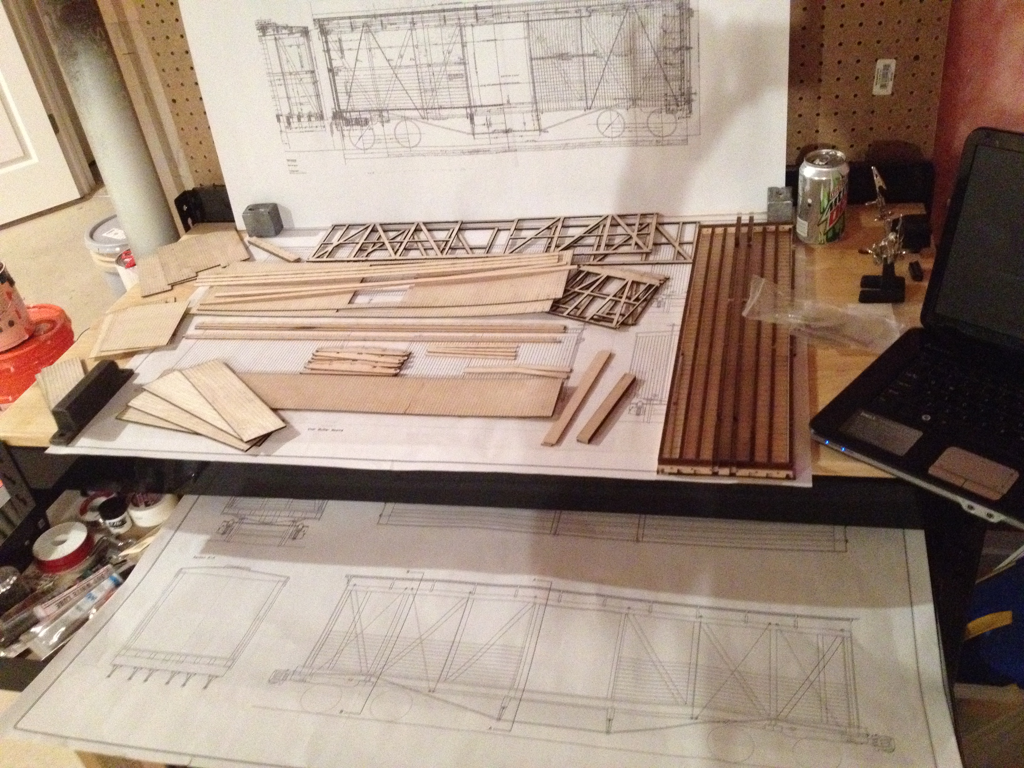
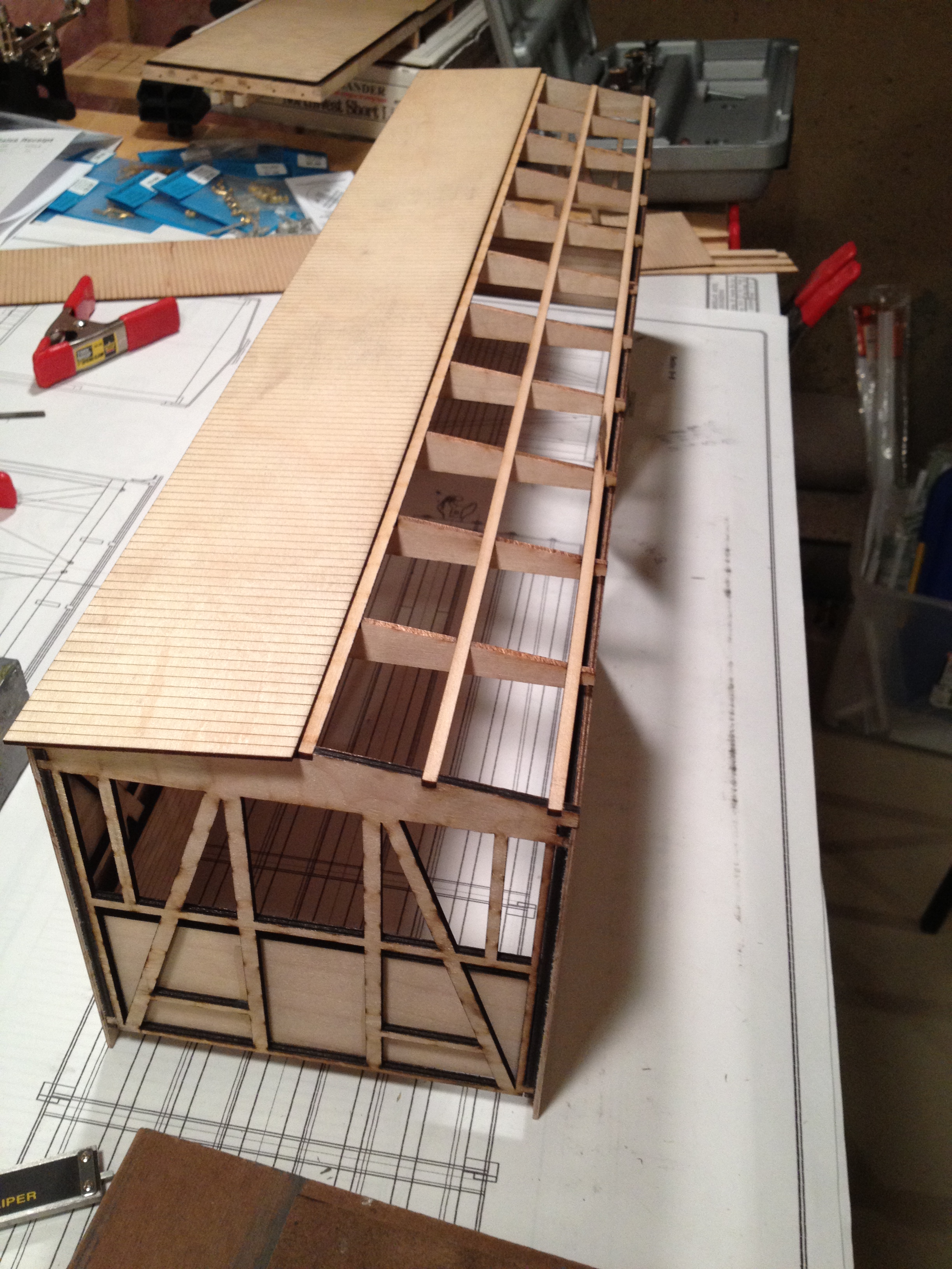
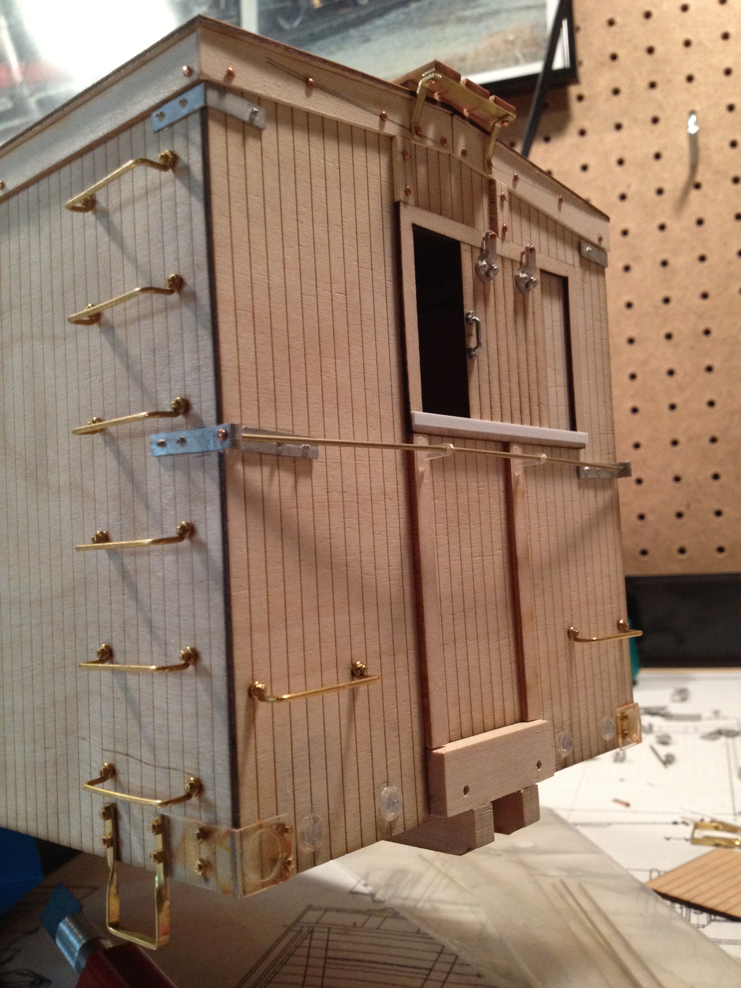
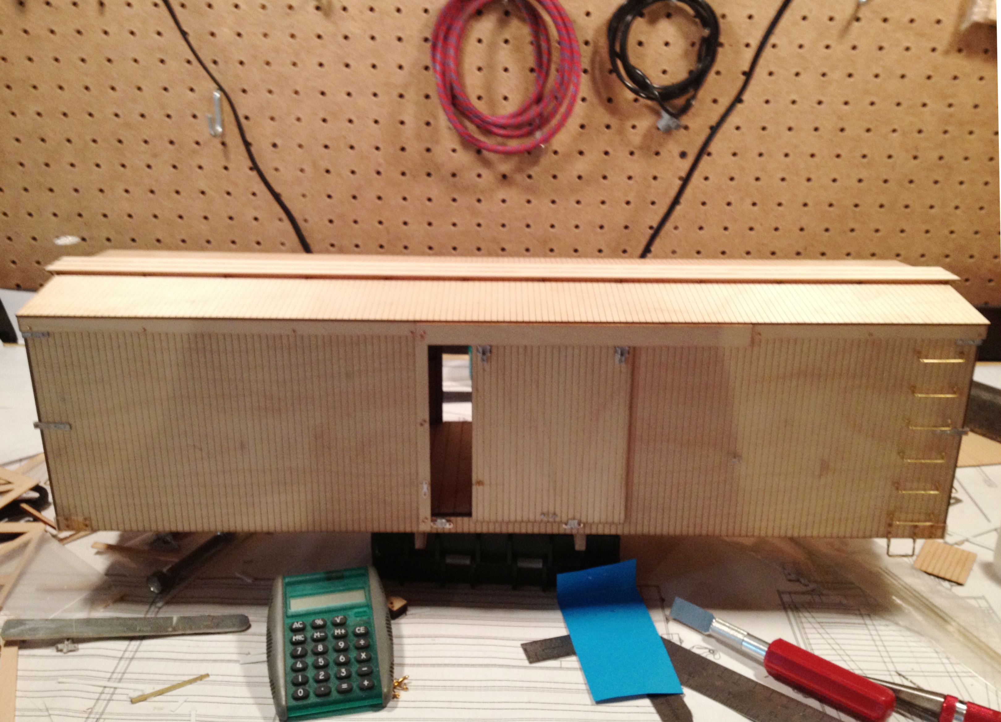
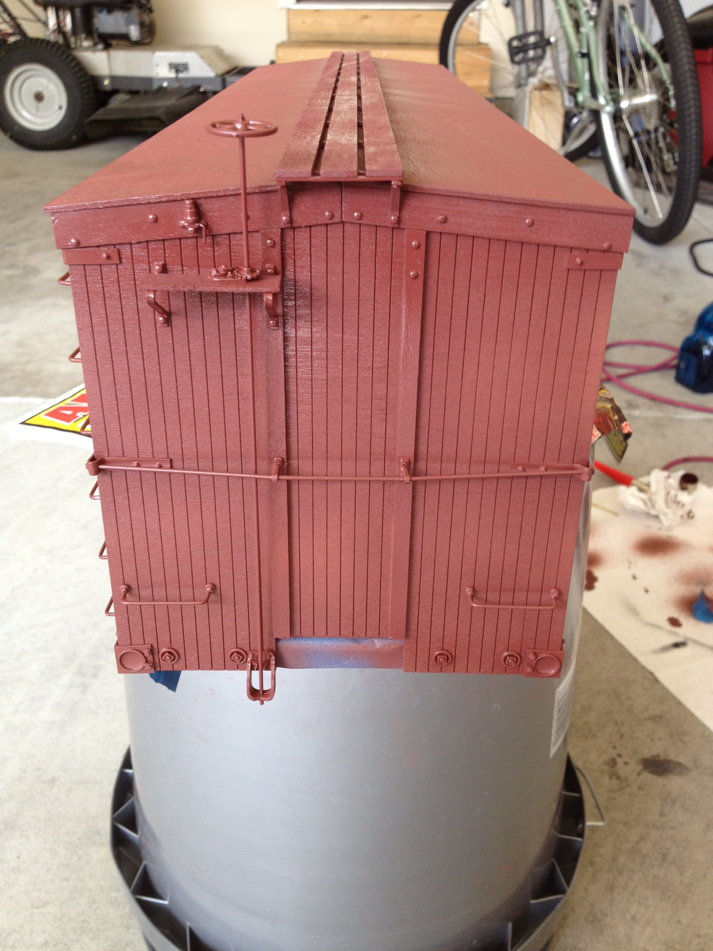
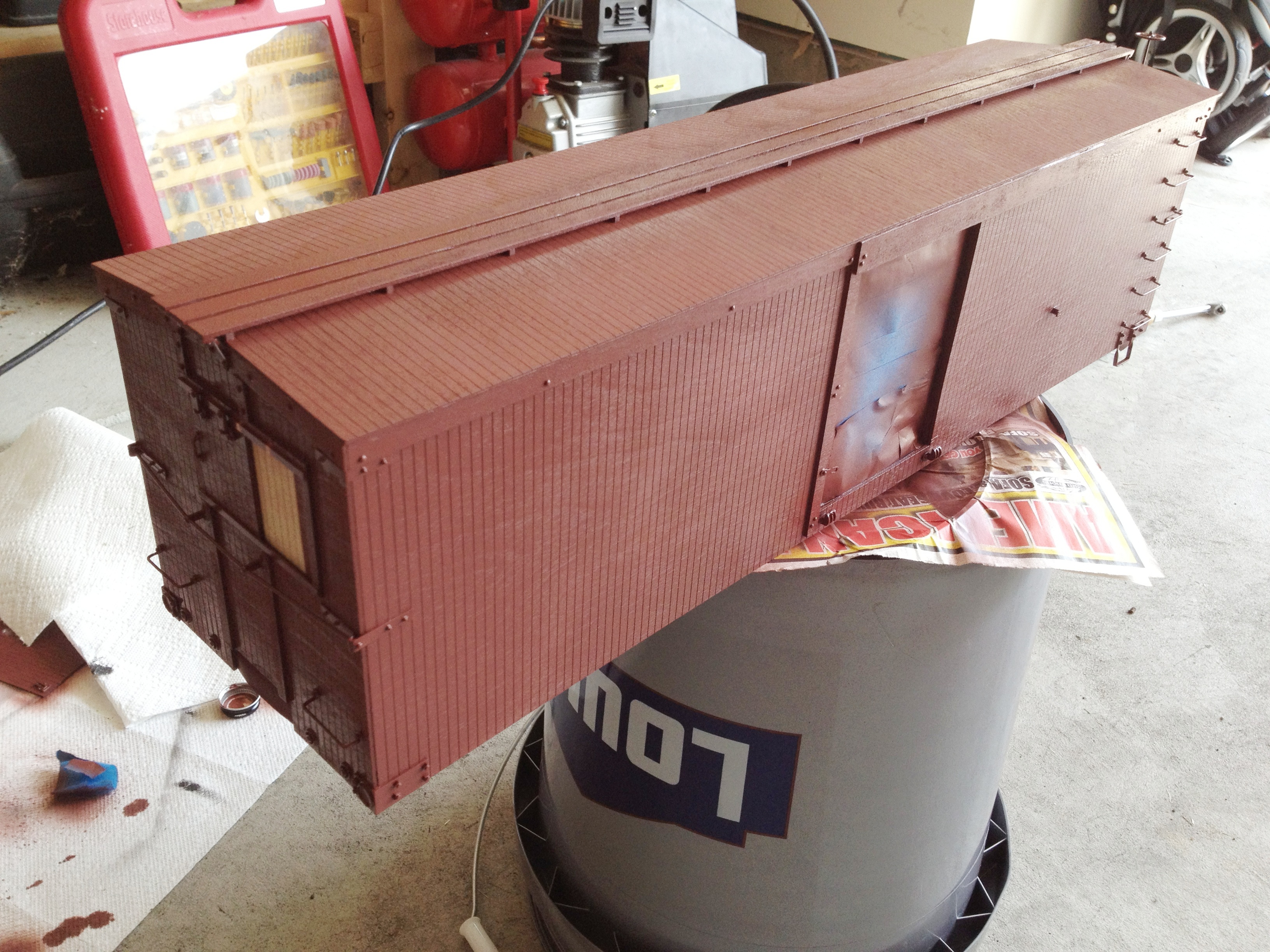
.jpg) %20013b.jpg) .jpg) 30
Ton SR Boxcar Kit
(updated 5-22-12) 30
Ton SR Boxcar Kit
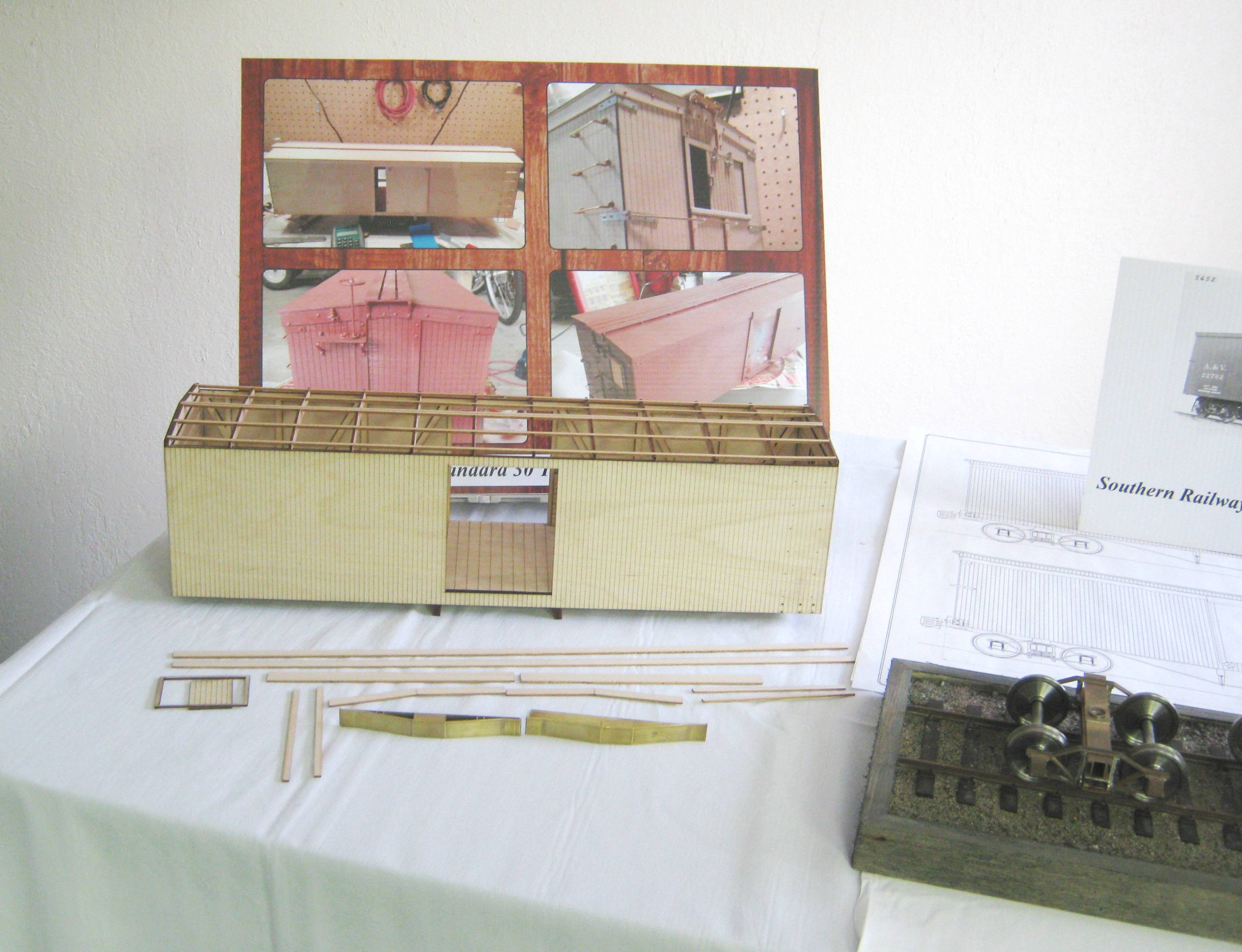
(updated 5-22-12)Since January of 2010 when I took delivery of my 120 watt Rabbit USA laser cutter, I have been anticipating the development of several 1:20.3 standard gauge freight car kits. The first of these is now nearly ready to enter production, pending the completion of truck, bolster and draft gear patterns. The first Cumberland Kit will be the Southern Railway's standard 30 ton boxcar pictured at right. These 36' long cars were built as early as 1904 with subsequent repeat orders going through the WWI years. These cars were all wood, save for their trucks, body bolsters, trussrods, draft gear and other hardware components. They remained in service into the 1930s (at least as far as I can verify from local photographic collections). They are suitably generic so as to represent 36' cars on many other railroads of the same period. My thanks to the George "Ike" Eichelberger and the archives of the Southern Railway Historical Association for providing scans of the linen blueprints used to build these cars.
|
|
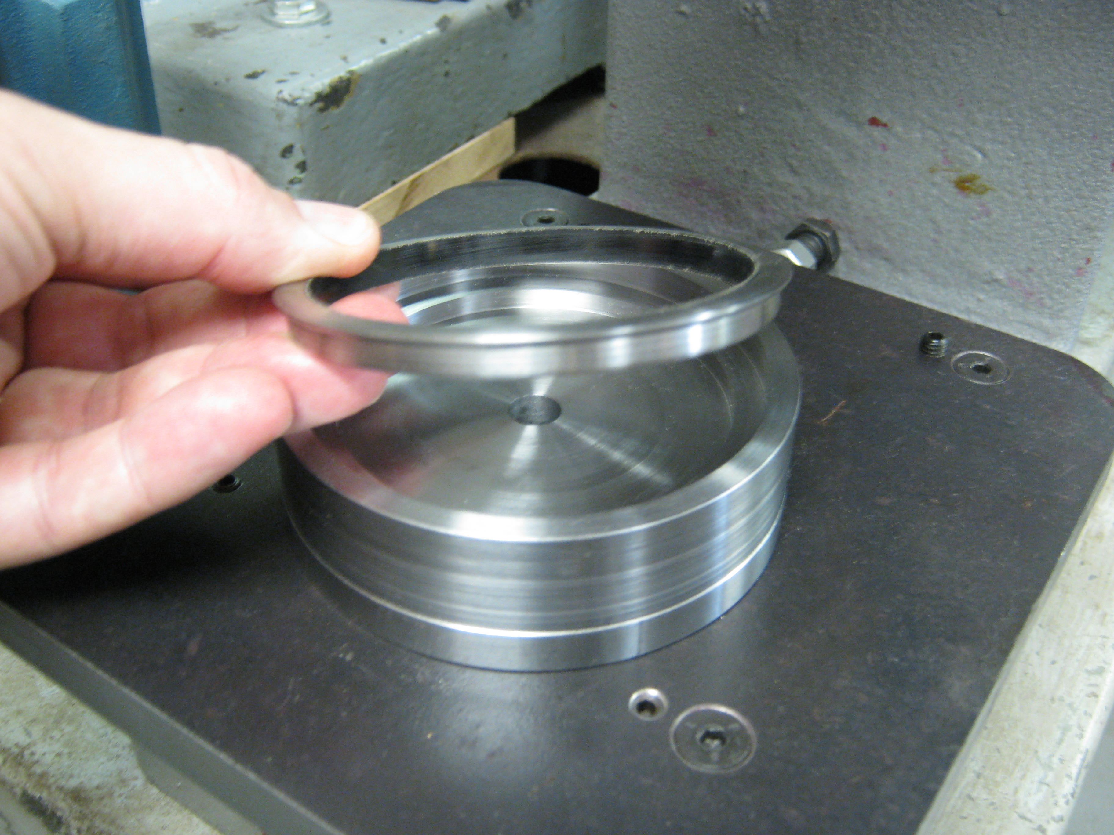
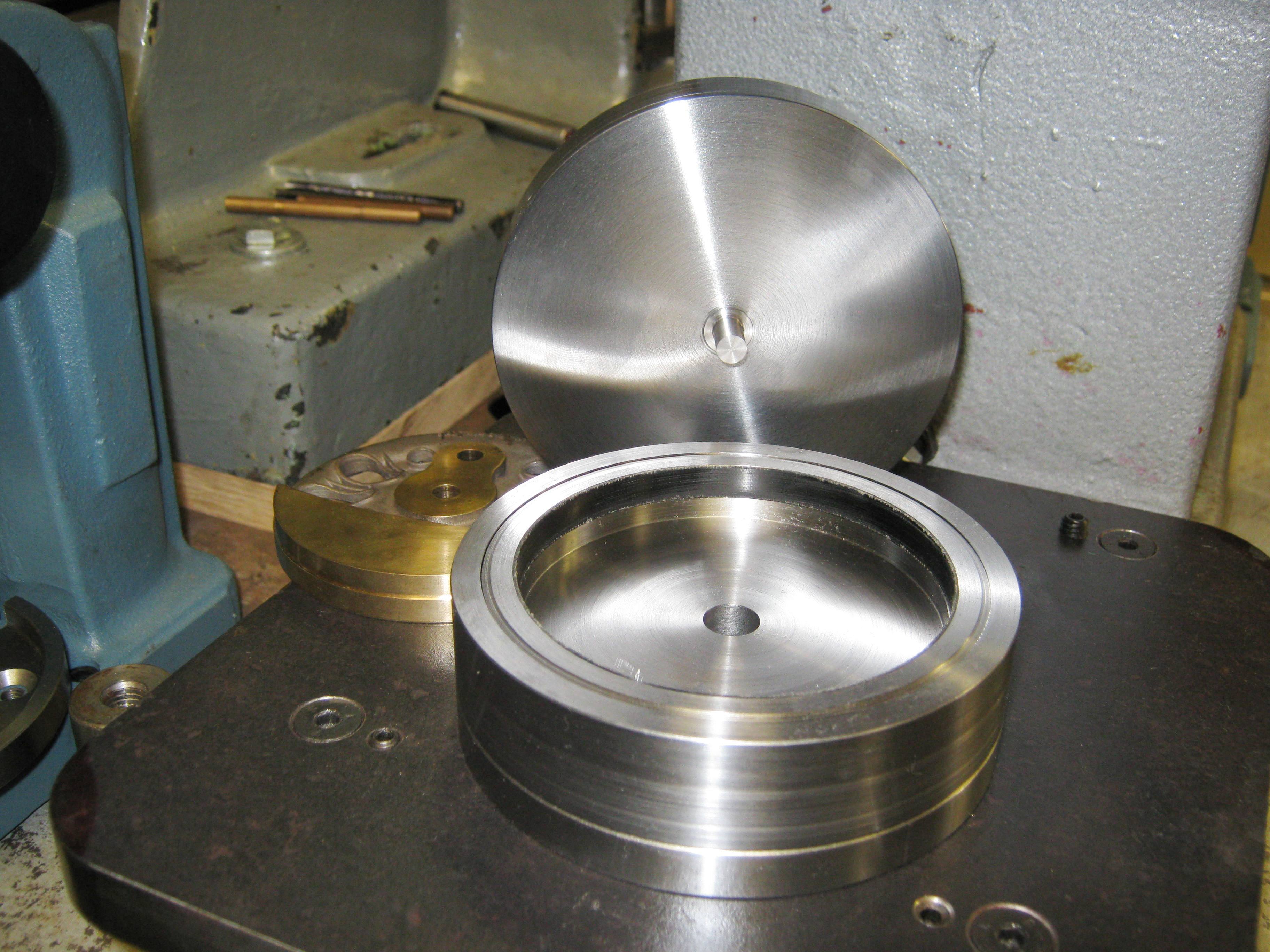
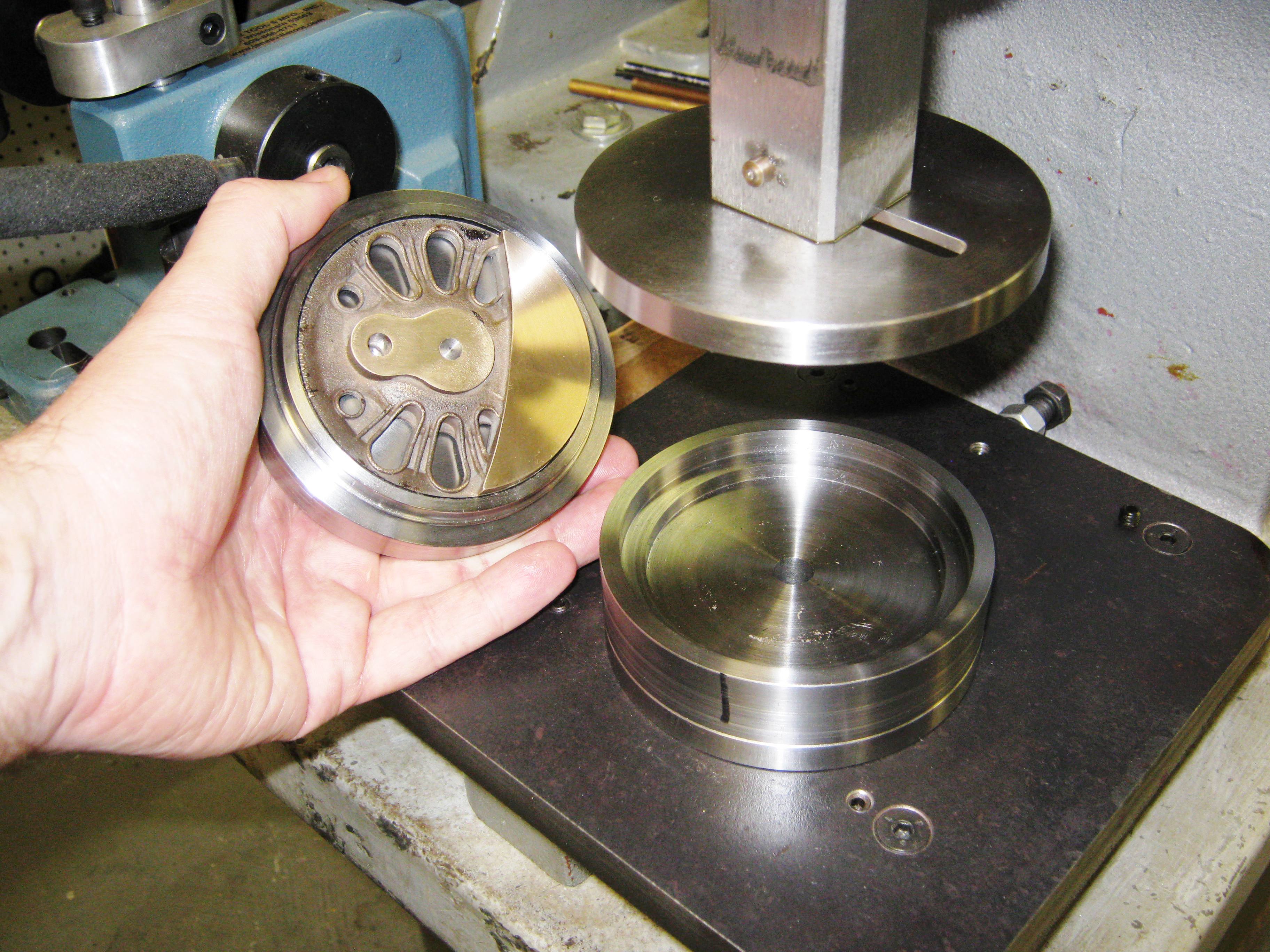
.jpg) .jpg) More D&RGW
L-105 Driver Progress
(updated 5-22-12) More D&RGW
L-105 Driver Progress
(updated 5-22-12)March and April of this Spring has been spent in no small measure working on suitable tooling for assembling the 70" Baldwin disc drivers on Doug Hemmeter's D&RGW L-105 challenger. The issue was fairly simple: How to insulate each driver between the tyre and its center with a strip of plastic. The initial problem was one of both technique and material: the .003" Mylar I wrapped around each driver center and then placed a heated tyre around, tended to flow as it cooled, causing an electrical short circuit. Solution: A thicker material (in this case .020" linen-backed phenolic plastic) with a cup and die to cold press the driver center into the tyre. Interference between the tyre w/ insulator and the driver center is .001" per inch of driver center OD. The cup has a step for the tyre and insulator to rest upon and is bored sufficiently deep so as to clear the driver center's counterweight. The corresponding lid on the cup has a centering pin which locates the driver center, and the whole assembly is placed into mating cups on the same arbor press that I use as step #2 in the processes of quartering drivers. In the future, I hope to have a tutorial page set up on this site so that you can make your own tooling.
|
|
.jpg) Cranky
Cranky Crank Pins
(updated 4-20-12) Cranky
Cranky Crank Pins
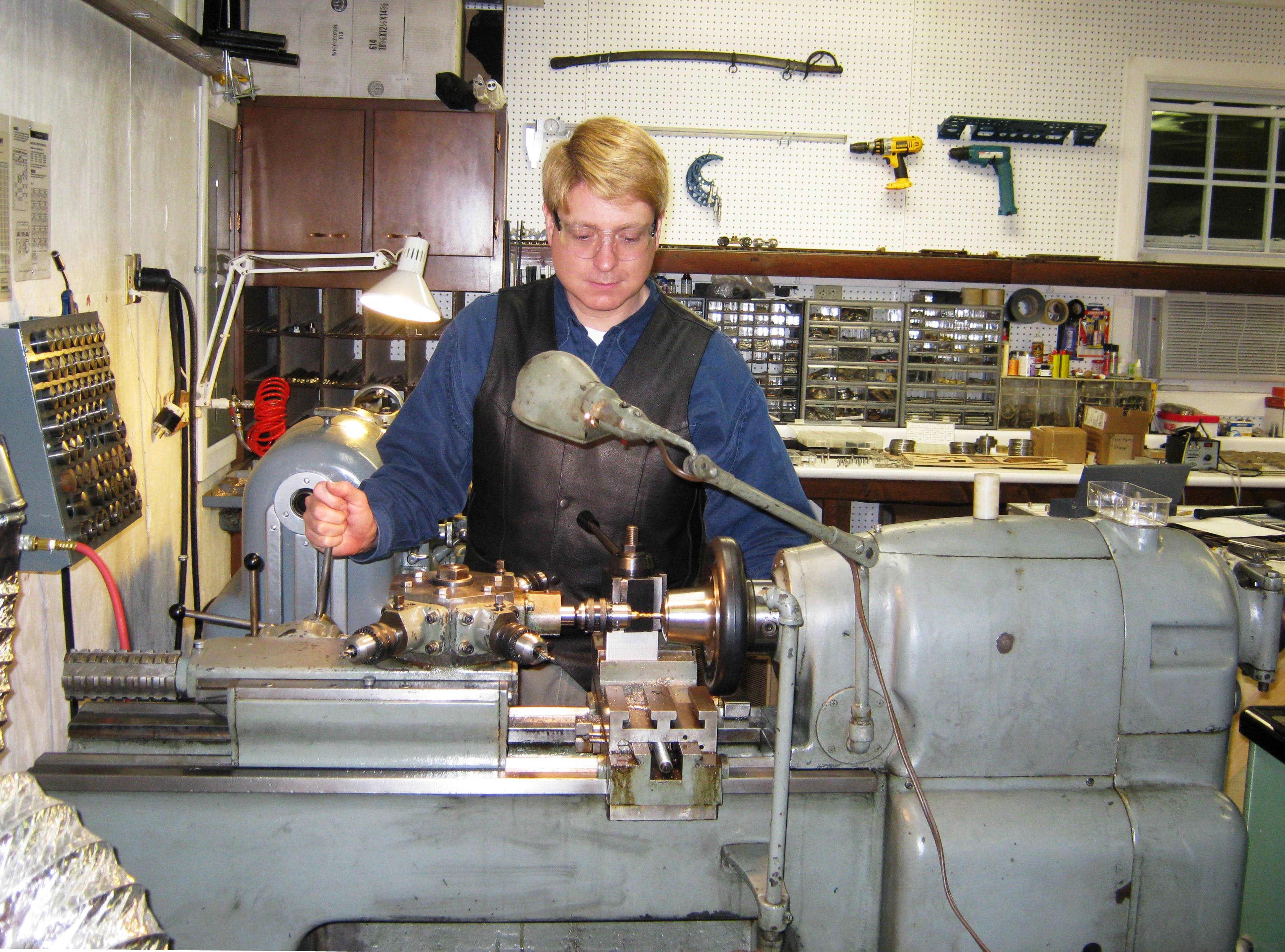
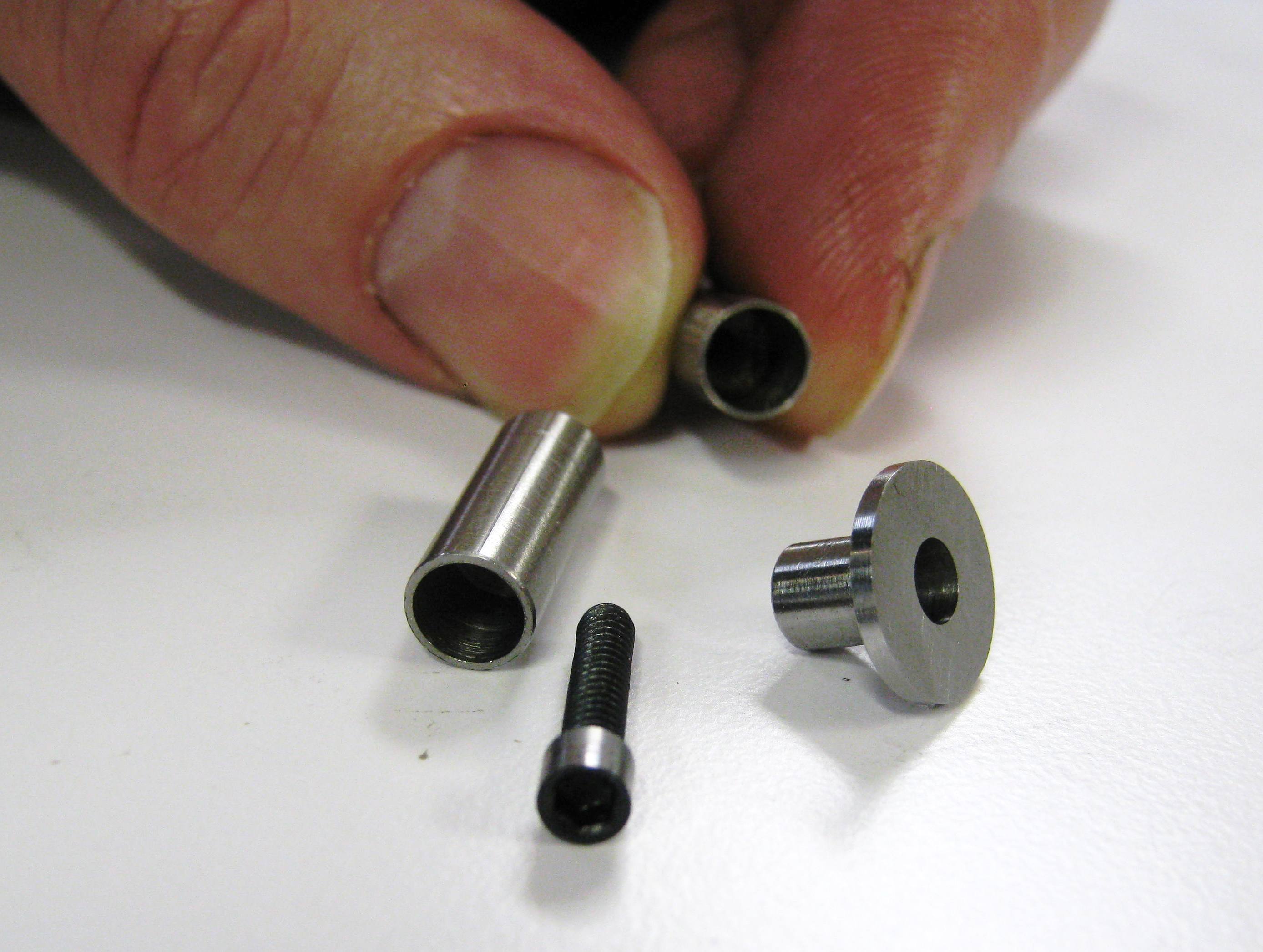
(updated 4-20-12)What do steam locomotive crankpins look like in F scale. Something like this. The L-105 Challenger has three sizes of crankpin, turned from 303 stainless rod in 1/4" and 3/8" OD. In order to fit between the narrow clearances of the crosshead guides and the extreme width of each driver face, the crankpins on each lead pair of drivers are made from multiple parts, using countersunk 4-40 socket head cap screws to secure a flanged rod which itself keeps the lead side rod in place. Each of these crankpins was turned on my 1945 Monarch 10EE turret lathe. Assembly was then done in a special jig on my Bridgeport clone by pressing home each crankpin.
|
|
| Continue to CME News 2011 . . . | |
|
Last update: 7 January 2014
| |
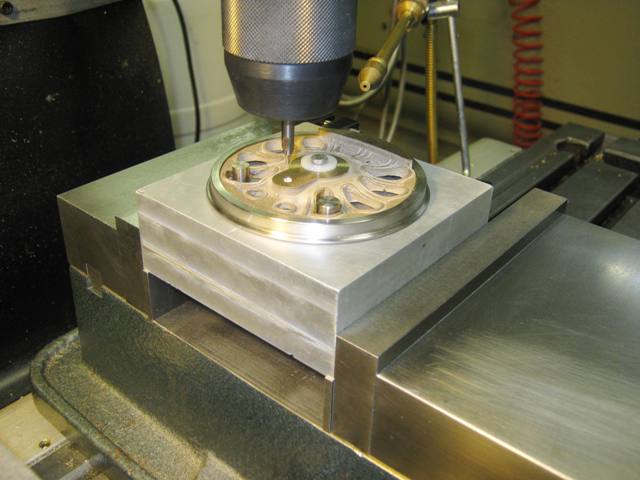
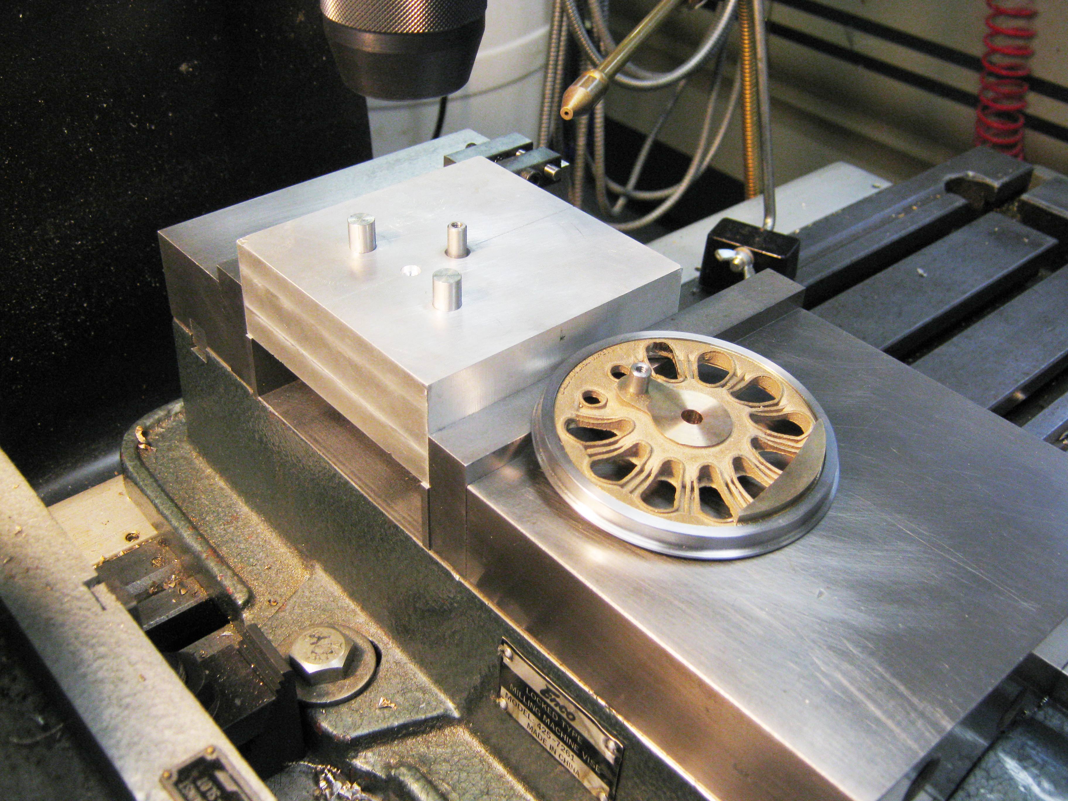
%20024(250).jpg) For some time I have been wanting to create a
tutorial on machining drivers, starting with the investment cast
driver center and then proceeding through the tooling needed to
create separate steel tyres, insulated about the rims. Towards that end, I created the first part of a video
tutorial in June of 2012. In the fist video, were are using my
Ps-4 Pacific driver centers as examples, but much of the rest of
the planned tutorial will cover how I did it with the Baldwin Disc drivers
(above) which were completed about the same time for Doug Hemmeter and shipped out to Mr.
Rodney Edington who was milling the L-105's main frames from
brass bar stock (see above entry). Enjoy!
For some time I have been wanting to create a
tutorial on machining drivers, starting with the investment cast
driver center and then proceeding through the tooling needed to
create separate steel tyres, insulated about the rims. Towards that end, I created the first part of a video
tutorial in June of 2012. In the fist video, were are using my
Ps-4 Pacific driver centers as examples, but much of the rest of
the planned tutorial will cover how I did it with the Baldwin Disc drivers
(above) which were completed about the same time for Doug Hemmeter and shipped out to Mr.
Rodney Edington who was milling the L-105's main frames from
brass bar stock (see above entry). Enjoy!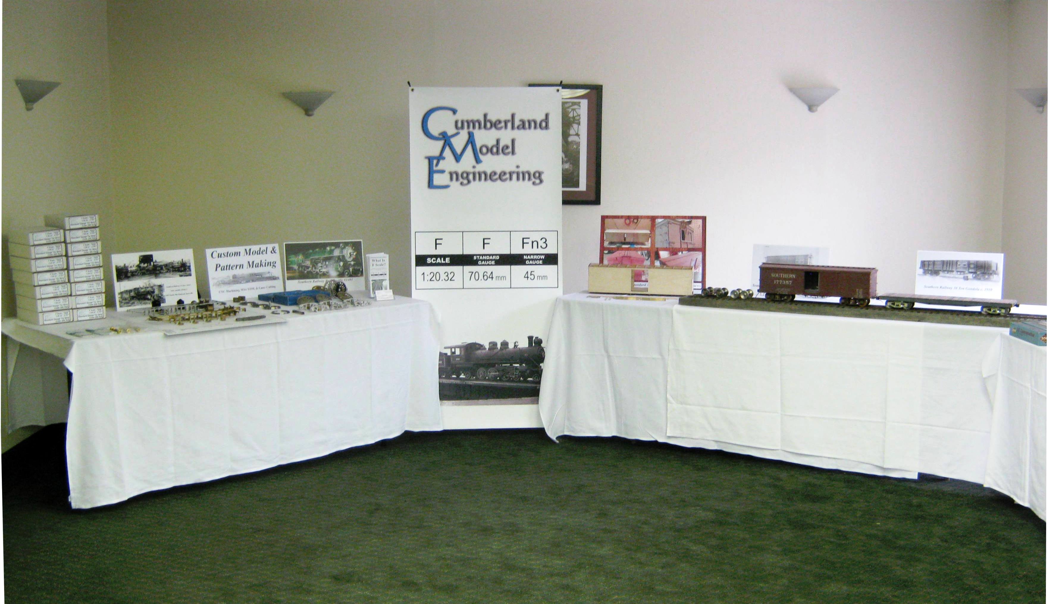
%20071a.jpg)
%20030.jpg)
%20023.jpg)
%20017.jpg)